UWB Partial Ground with Slit Circular
Microstrip Patch Antenna Design
Amit Kumar, Bhavneesh Malik
M.Tech Student, Dept. of ECE, RIEM, Rohtak, MDU Rohtak, India
Head, Dept. of ECE, RIEM, Rohtak, MDU Rohtak, India
ABSTRACT: In this paper different kind of Ultra Wideband (UWB) microstrip antenna consisting of a circular monopole patch with stepped feed line, with a 10 dB return loss bandwidth from 2 to 10 GHz is designed. This antenna was designed onFR4 substrate and dielectric substrate with = 4.4. These antenna operated at UWB frequency and it designed by using CST Software based on the characteristic impedance for the transmission line model. The parameters like substrate dimension, feed size and ground plane which affect the performance of the antenna in terms of its frequency domain and time domain characteristics are investigated.
KEYWORDS: Microstrip line feed, Microstrip antenna, Partial ground plane, Ultra Wideband Antenna
I. INTRODUCTION
A microstrip antenna is one who offers low profile and light weight. It is a wide beam narrowband antenna can be manufactured easily by the printed circuit technology such as a metallic layers in a particular shape is bonded on a dielectric substrate which forms a radiating element and another continuous metallic layer on the other side of substrate as ground plane. Not only the basic shapes any continuous shape can be used as the radiating patch. Instead of using dielectric substrate some of the microstrip antennas use dielectric spacers which results in wider bandwidth but in the cost of less ruggedness. Microstrip antennas are low profile antenna and mechanical rugged and can be easily mounted on any planar and non-planar surfaces. The size of microstrip antenna is related to the wavelength of operation generally /2. The applications of microstrip antennas are above the microwave frequency because below these frequencies the use of microstrip antenna doesn’t make a sense because of the size of antenna. At frequencies lower than microwave, microstrip patches don't make sense because of the sizes required. Now a day’s microstrip antenna is used in commercial sectors due to its inexpensiveness and easy to manufacture benefit by advanced printed circuit technology. Due to the development and ongoing research in the area of microstrip antenna it is expected that in future after some time most of the conventional antenna will be replaced by microstrip antenna.
UWB has a number of encouraging advantages that are the reasons why it presents a more eloquent solution to wireless broadband than other technologies. Firstly, according to Shannon-Hartley theorem, channel capacity is in proportion to bandwidth. Since UWB has an ultra wide frequency bandwidth, it can achieve huge capacity as high as hundreds of Mbps or even several Gbps with distances of 1 to 10 meters Secondly, UWB systems operate at extremely low power transmission levels. By dividing the power of the signal across a huge frequency spectrum, the effect upon any frequency is below the acceptable noise floor [2]. A Ultra Wideband technology is defined as a system that occupied over 500MHz of bandwidth or occupy a fractional bandwidth of 20% or greater. Ultra Wideband uses radio modulation technique to achieve a wide bandwidth by transmitting very short pulses (in nanosecond or less) with very low power utilization. This makes Ultra Wide band differs from conventional narrowband systems. Starting 2002, the usage of unlicensed Ultra Wideband operation was authorised by FFC (Federal Communication Commission) of United States of America (USA) [1].
extraneous radiation from feeds and junctions, poor end fire radiator except tapered slot antennas, low power handling capacity and surface wave excitation [3, 4].
The whole paper is organized in four sections. In the First section we will describe microstrip patch antenna’s different models. In second section we describe different geometrical shapes and design parameters. After that we discuss the results obtained and in the last we will explain the future scope of the antenna’s.
1. Microstrip antenna’s analytical model:
II. CIRCULAR MICROSTRIP ANTENNA
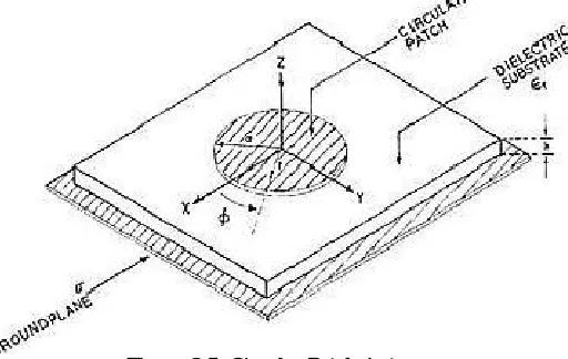
Circular patch is the second most widely used geometry for the microstrip patch antenna. As in rectangular microstrip antenna we have two degree of freedom (length and width) to control the antenna characteristics, here we have only radius of circular patch. A circular microstrip antenna is shown in figure below
Figure 3.5 Circular Patch Antenna
As shown in figure Metallic Circular patch with radius a is placed a height h above the ground plane. Dielectric substrate separates the patch and ground plane and the patch is fed at a point r distance from the centre at a angle from the x-axis. The circular patch antenna can be analysis by considering the patch as a cavity with two perfect conductor electric wall above and below (patch and ground plane) and magnetic walls along the edges. The electric field below the circular patch can be given by:
= ( )cos( ∅)
And the magnetic field components can be given by:
=− ( ) sin( ∅)
∅=− ′ ( ) cos( ∅)
Where,
k = propagation constant
=nth order Bessels function
′ = nth order derivative of Bessels function
The resonance frequency fmnrelated to TM mode can be given as:
= .
2 √ Where
= mth zero of derivative of Bessel’s function of nth order c = velocity of light in free space
= . 1 + 2ℎ ln
2ℎ + 1.7726 ℎ≫1
and the actual radius of patch can be determined by
= .
2 √ 1 +
2ℎ
ln
2 ℎ + 1.7726
Therefore radius of circular patch can be found using above equation.
III. PROPOSED PATCH ANTENNAS
3.1Modified Circular Patch Antenna for UWB application
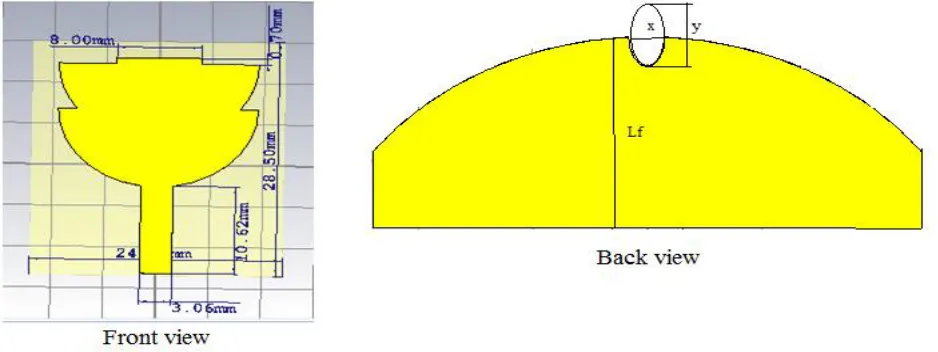
The designed antenna has two half circular patches which are overlapped to each other. A narrow rectangular slit is added to the patch to improve the performance of antenna. The proposed antenna is fabricated on an inexpensive and easily available dielectric material FR-4 with permeability of 4.4.
Figure 2 Front and Back View and Fabricated Antenna
Proposed microstrip antenna is fed by standard 50ohm microstrip feed line. Different parameters with their Optimized value of the proposed antenna are listed below in table:
Table 1 Dimensions of the Proposed 1st Design
Parameters Description Value (in mm)
R Radius of half circular patch 9.5
A Overlapping length 4
Lf Length of feedline 10
Wf Width of feedline 3.058
Lstub Length of stub 0.7
Wstub Width of stub 8
Lsub Length of substrate 29.8
Wsub Width of substrate 12.6
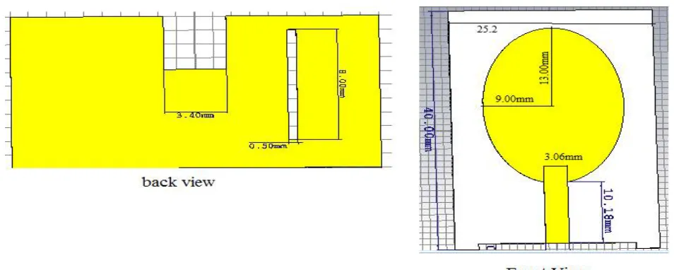
3.2 Elliptical Shape Microstrip Patch Antenna with Modified Groundplane
antenna is a good candidate to be used for the UWB application. Partial ground plane is used here. For increasing the bandwidth as a ground plane strategy a rectangular notch and a narrow slit is made in the ground plane.
Figure 3 front and back view of proposed antenna
Parameter list with their values are written in the table below. All the dimensions are in millimetre.
Table 2 Dimensions of the Proposed 2nd Design
Parameters Description Value (in mm)
X Major radius of ellipse 9
Y Minor radius of ellipse 13
Lf Length of feedline 10
Wf Width of feedline 3.058
A Length of notch 3.4
B Width of notch 3.858
Lsub Length of substrate 38.6
Wsub Width of substrate 25.2
L1 Length of slit 8
W1 Width of slit 0.5
IV. SIMULATION RESULTS
The s11 vs frequency curve for the optimized parameters is shown below.
Figure 4. frequency vs s11 curve for optimized values
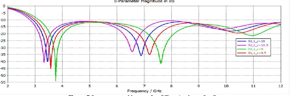
The effect of modifying the radius of patch effect on s11 parameter is observed. Figure below shows different s11 vs frequency curve for different values of radius r. It is observed that when we increase the radius the s11 vs frequency curve shifts towards lower frequency while on decreasing it shifts toward right. Therefore we can conclude that the two resonance frequencies we are getting are inversely proportional to the radius of the circular patch. It is also observed that for optimum value of radius r=9 the s11 is more deep.
Figure 5 frequency vs s11 curve for different values of radius r
Figure 6 frequency vs s11 curve for different values of a
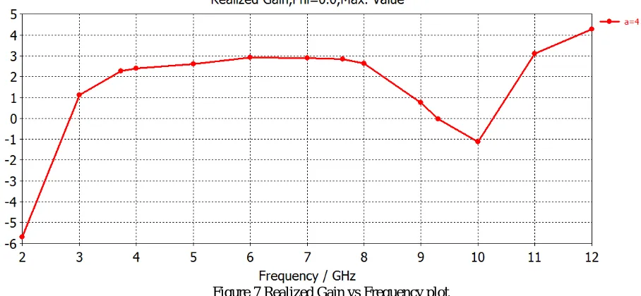
From the results it is clear that when the overlapping of the patches increases or decreases from its optimum value a=4 the s11 vs frequency curve shift upwardFigure below showing the Gain vs frequency curve. Antenna have maximum gain at 12 GHz 4.2 dB and minimum -5.6 dB and -1.1 dB at 2 GHz and 10 GHz respectively.
Figure 7 Realized Gain vs Frequency plot
4.2 Simulation Results of elliptical patch antenna:
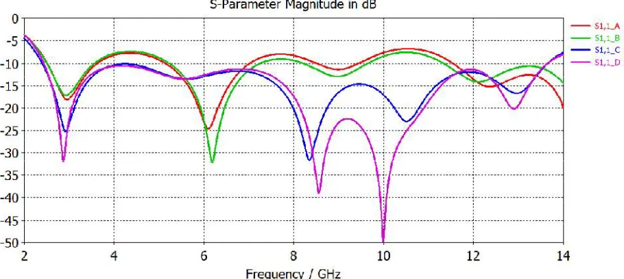
Figure 8 Return loss curve for different modifications in ground.
From graphs it can be observe that making the edges of rectangular ground plane smooth will not affect the return loss curve in lower frequency but at higher frequency it improves the return loss curve, the return loss curve shifts downside. By making a rectangular notch in ground plane just below the feedline results in drastically increase in the bandwidth. By introducing a narrow rectangular slit curve moves further downside.
The return loss curve for different position of rectangular slit related to centre line is also observed. It is observed that changing the relative position of the slit not affects so much in lower frequency but effects on higher frequency.
Figure 9 Return loss curve for different position of slit.
Figure 10 Return loss curve for different value of notch length b
Figure 11 Return loss curve for different value of notch width a
From the above two graphs it is observed that the effect of notch dimension on return loss curve is more for the higher frequency as compared to lower frequencies
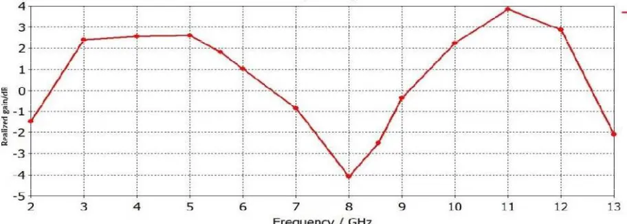
The realized gain plot are shown below, With maximum 4dB at 11GHz and minimum -4dB at 8GHz.
V. CONCLUSION
This paper describes two different microstrip patch antenna designs with different shapes. Both are designed to work in UWB with different band notches for different applications like (WiMAX) operating in 3.3-3.7 GHz, (WLAN) for IEEE 802.11a 5.15-5.825 GHz, Downlink X-band satellite communication systems in 7.25 - 7.75 GHz.4.5-4.8 GHz INSAT / Super-Extended C-Band (Indian National Satellite systems). The easiest and most common method to achieve a band notch is making a narrow slot of different shapes into the radiating patch of the antenna, will affect the current flow in the patch, different type of shapes is used to make the slots are used to get the band-notched in the desired frequency band. These proposed antenna structure’s simulation is carried out using the CAD software Microwave Studio in Computer Simulation Technology Simulator (CST), one commercial 3-D full-wave electromagnetic simulation software. The Simulated results are presented, shows the usefulness of the proposed antenna structure for UWB applications
REFERENCES
[1] Bernhard, J.T., Mayes, P.E., Schaubert, D., and Mailoux, R.J.,”A commemoration of Deschamps’ and Sichak’s ‘Microstrip Microwave Antennas’: 50 years of Development, divergence,and new directions,” Proceedings of the 2003 Antenna Applications Symposium , Moticello, IIIinois, september 2003, pp. 189-230.
[2] Randy Bancroft, 2nd edition, ”Microstrip and Printed Antenna Design”.
[3] Gutton, H., and Baissinot, G., “Flat aerial for ultra-high frequencies,” French Patent no. 703113, 1955.
[4] Barret, R. M., “Microwave printed Circuits-a historical survey,” IEEE Transactions on microwave Theory and techniques, vol.3, No.2, pp. 1-9. [5] Denlinger, E.J., “Radiation from Microstrip Radiators” IEEE Transactions on microwave Theory and techniques, April1969, vol.17, No. 4, pp. 235-236.
[6] IEEE Transactions on antenna and propagation, January 1981.
[7] Lo, Y.T., Solomon, D.,and Richards , W.F.,”Theory and Experiment on microstrip Antenna,” IEEE Transactions on antenna and propagation, March1979, vol. AP-27, pp. 137-149.
[8] Richards, W.F., LO, Y.T., and Harrison, D.D., “An improved theory for microstrip antennas and application” IEEE Transactions on antenna and propagation January 1981,vol. AP-29,pp. 38-46.