DEFINITY
Enterprise Communications Server
Release 6
Installation and Test for Multi-Carrier Cabinets
555-230-112
Comcode 108215526
Issue 5
All Rights Reserved Printed in U.S.A.
Notice
Every effort was made to ensure that the information in this book was complete and accurate at the time of printing. However, information is subject to change.
Your Responsibility for Your System’s Security
Toll fraud is the unauthorized use of your telecommunications system by an unauthorized party, for example, persons other than your com-pany’s employees, agents, subcontractors, or persons working on your company’s behalf. Note that there may be a risk of toll fraud associated with your telecommunications system and, if toll fraud occurs, it can result in substantial additional charges for your telecommunications services.
You and your system manager are responsible for the security of your system, such as programming and configuring your equipment to pre-vent unauthorized use. The system manager is also responsible for reading all installation, instruction, and system administration docu-ments provided with this product in order to fully understand the fea-tures that can introduce risk of toll fraud and the steps that can be taken to reduce that risk. Lucent Technologies does not warrant that this product is immune from or will prevent unauthorized use of com-mon-carrier telecommunication services or facilities accessed through or connected to it. Lucent Technologies will not be responsible for any charges that result from such unauthorized use.
Lucent Technologies Fraud Intervention
If you suspect that you are being victimized by toll fraud and you need technical support or assistance, call Technical Service Center Toll Fraud Intervention Hotline at 1 800 643-2353.
Federal Communications Commission Statement
Part 15: Class A Statement. This equipment has been tested and found to comply with the limits for a Class A digital device, pursuant to Part 15 of the FCC Rules. These limits are designed to provide rea-sonable protection against harmful interference when the equipment is operated in a commercial environment. This equipment generates, uses, and can radiate radio-frequency energy and, if not installed and used in accordance with the instructions, may cause harmful interfer-ence to radio communications. Operation of this equipment in a resi-dential area is likely to cause harmful interference, in which case the user will be required to correct the interference at his own expense. Part 68: Network Registration Number. This equipment is registered with the FCC in accordance with Part 68 of the FCC Rules. It is identi-fied by FCC registration number AS593M-13283-MF-E. Refer to “Federal Communications Commission Statement” in “About This Book” for more information regarding Part 68.
Canadian Department of Communications (DOC) Interference Information
This digital apparatus does not exceed the Class A limits for radio noise emissions set out in the radio interference regulations of the Canadian Department of Communications.
Le Présent Appareil Nomérique n’émet pas de bruits radioélectriques dépassant les limites applicables aux appareils numériques de la class A préscrites dans le reglement sur le brouillage radioélectrique édicté par le ministére des Communications du Canada.
Trademarks
Ordering Information
Call: Lucent Technologies Publications Center
Voice 1 800 457-1235 International Voice 317 361-5353 Fax 1 800 457-1764 International Fax 317 322-6699 Write: Lucent Technologies BCS Publications Center
2855 N. Franklin Road Indianapolis, IN 46219 Order: Document No. 555-230-112
Comcode 108215526 Issue 5, May 1998
For additional documents, refer to the section in “About This Docu-ment” entitled “Related Resources.”
You can be placed on a standing order list for this and other documents you may need. Standing order will enable you to automatically receive updated versions of individual documents or document sets, billed to account information that you provide. For more information on stand-ing orders, or to be put on a list to receive future issues of this docu-ment, contact the Lucent Technologies Publications Center. European Union Declaration of Conformity
The “CE” mark affixed to the DEFINITY® equipment described in this book indicates that the equipment conforms to the following Euro-pean Union (EU) Directives:
• Electromagnetic Compatibility (89/336/EEC) • Low Voltage (73/23/EEC)
• Telecommunications Terminal Equipment (TTE) i-CTR3 BRI and i-CTR4 PRI
For more information on standards compliance, contact your local dis-tributor.
Comments
To comment on this document, return the comment card at the front of the document.
Acknowledgment
Installation and Test for Multi-Carrier Cabinets 555-230-112 May 1998 Contents
Page iii
Contents
Contents iii
About This Book viii
■ Organization ix
■ How to Comment on This Book ix
■ Related Books x
■ How to Order Books x
■ Trademarks xi
■ Standards Compliance xii
■ LASER Product xiii
■ Electromagnetic Compatibility Standards xiii
■ Where to Call for Technical Support xv
■ Anti-Static Protection xv
■ Security Issues xv
■ Federal Communications Commission Statement xvi
1
Install and Connect Cabinets 1-1■ Unpack and Inspect Cabinets 1-1
■ Check Customer’s Order 1-2
■ Correcting Shipping Errors 1-2
■ Install System Cabinets 1-3
■ Connect AC Power and Ground 1-6
■ Connect DC Power and Ground 1-16
■ Approved Grounds 1-23
■ Connect Remote Power Off Cable and
External Alarm Cable 1-25
■ Connect External Alarm Cable 1-27
■ Connect AC Power to Stratum 3 Clock Cabinet 1-27
■ Connect DC Power and Ground to
Stratum 3 Clock Cabinet 1-28
■ Fiber Optic Interconnect Cabling 1-29
■ Earthquake Protection Installation 1-34
2
Install Telecommunications Cabling 2-1■ Equipment Room Hardware 2-1
■ Main Distribution Frame 2-4
Installation and Test for Multi-Carrier Cabinets 555-230-112 May 1998 Contents
Page iv
■ Install Equipment and Cables 2-6
■ Install Cable Slack Managers 2-12
■ Install Sneak Fuse Panels 2-13
■ Cable Installation 2-16
■ Install Coupled Bonding Conductor 2-26
■ Station Wiring Design 2-28
■ Station Circuit Distribution from Equipment Room 2-33
■ Layout 2-39
■ Voice and Data Terminals 2-40
■ Label the Main Distribution Frame 2-44
■ Patch Cord/Jumper Installation and Administration 2-45
■ Create a Provisioning Plan 2-49
3
Install Management Terminal andActivate System 3-1
■ Install Management Terminal 3-2
■ Activate the System 3-7
■ Screens and Commands 3-10
■ System Administration 3-11
■ Set Country Options 3-12
■ Circuit Pack Administration 3-17
■ Set System Maintenance Parameters 3-18
■ Administer System Configurations (Release 6r) 3-19
■ Administer Fiber Links (Release 6r Only) 3-23
■ Reboot High Reliability System 3-29
■ Administer Attendant Console 3-29
■ Save Translations 3-30
■ Add Translations 3-30
■ Installation Completion 3-31
■ DEFINITY AUDIX Power Procedures 3-32
4
Test the System 4-1■ Check System Status for Each Cabinet 4-2
■ Check Circuit Pack Configuration 4-3
■ Test TDM Bus in PPN 4-4
■ Test Tone-Clock Circuit Packs 4-5
Installation and Test for Multi-Carrier Cabinets 555-230-112 May 1998 Contents
Page v
■ Test Duplicated Switch Processing
Element Interchange 4-7
■ Test Expansion Interface Circuit Packs 4-8
■ Test TDM for each EPN 4-9
■ Test Tone-Clock for each EPN 4-10
■ Test Tone-Clock Interchange for each EPN 4-10
■ Test Expansion Interface Exchange for Each EPN 4-11
■ Check Circuit Pack Configuration Again 4-12
■ System Test Completion 4-12
■ LED Indicators 4-13
5
Install and Wire Telephones andOther Equipment 5-1
■ Analog Station or 2-Wire Digital Station Example 5-5
■ Analog Tie Trunk Example 5-6
■ Digital Tie Trunk Example 5-7
■ DS1 Tie Trunk Example 5-8
■ Auxiliary Connector Outputs 5-10
■ Three-Pair and Four-Pair Modularity 5-13
■ Adjunct Power Connections 5-14
■ Attendant Console 5-16
■ 26B1 Selector Console 5-16
■ Connect External Alarm Indicators 5-17
■ Connect Power Distribution Unit External Alarm Wires 5-19
■ Remote Network Interface 5-22
■ TN1654 DS1 Converter (Release 6r Only) 5-23
■ Off-Premises Station Wiring 5-30
■ Off-Premises or Out-of-Building Stations 5-30
■ Emergency Transfer Units and Associated Telephones 5-36
■ External Ringing 5-44
■ Queue Warning Indicator 5-44
■ 1145B Power Supply 5-45
■ 1151A Power Supply 5-54
■ BRI Terminating Resistor 5-57
■ Multi-point Adapters 5-61
■ Add Circuit Packs 5-64
Installation and Test for Multi-Carrier Cabinets 555-230-112 May 1998 Contents
Page vi
■ Add the Fiber Optic Cable 5-70
■ Add CO, FX, WATS, and PCOL 5-85
■ Add DID Trunks 5-86
■ Add Tie Trunks 5-87
■ Add DS1 Tie and OPS 5-89
■ Add Code Calling Access 5-93
■ Add Speech Synthesis 5-93
■ Add Pooled Modem 5-93
■ Add External Modem to EPN 5-94
■ Add External Modem to PPN 5-95
■ Add External Modem to TN1648B 5-96
■ Add Multiple Announcement 5-106
■ Add ISDN — PRI 5-110
■ Add Packet Bus to R6si 5-113
■ Add CallVisor ASAI 5-117
■ Add ISDN—BRI 5-121
■ Add PRI Over PACCON to R6si 5-124
■ CAMA/E911 Installation 5-131
■ Connector and Cable Diagrams (Pinout Charts) 5-143
6
Test Telephones and Other Equipment 6-1■ Make Test Calls 6-2
■ Test 302C Attendant Console 6-2
■ Test External Ringing 6-3
■ Test Queue Warning Indicator 6-3
■ Test Integrated Announcement 6-3
■ Test Music-on-Hold 6-4
■ Test Emergency Transfer 6-4
■ Test Remote Access Interface 6-4
■ Test Basic Rate Interface 6-5
■ Test Duplication Option Processing
Element Interchange 6-5
■ Test Terminating Trunk Transmission 6-6
■ Test Stratum 3 Clock 6-7
■ Perform Complete System Test 6-8
Installation and Test for Multi-Carrier Cabinets 555-230-112 May 1998 Contents
Page vii
A
Connecting Fiber Optic Cables A-1■ LASER Product A-2
■ Fiber Optic Requirements A-2
■ Optical Cross-Connect Hardware A-6
■ Cleaning Fiber Optic Cables A-16
■ Labels for Fiber Optic Cables A-16
■ Making Changes at an LIU or Shelf A-17
■ Routing Fiber Optic Cables A-18
B
Option Switch Settings B-1■ External Modem Option Settings B-2
■ Printer Option Settings B-5
■ Call Detail Recording Option Settings B-8
■ TN760D Tie Trunk Option Settings B-10
■ TN464E/F Option Settings B-12
C
Cable Ductwork C-1D
Connector and Cable Diagrams D-1E
References E-1■ Basic DEFINITY ECS Documents E-1
■ Call Center Documents E-5
■ Application-Specific Documents E-6
■ Documents on CD-ROM E-9
GL
Glossary and Abbreviations GL-1About This Book
Page viii
Installation and Test for Multi-Carrier Cabinets 555-230-112 May 1998
About This Book
This book provides procedures and information for installing and initially testing the DEFINITY® Enterprise Communications Server Multi-Carrier Cabinets.
This document covers information related to DEFINITY ECS Release 6. For details about changes for Release 6, refer to DEFINITY Enterprise
Communications Server Release 6.1, Change Description.
The following conventions describe the systems referred to in this book.
■ The word system, is a general term and includes references to the DEFINITY Enterprise Communications Server
■ DEFINITY Systems are called: Release 5, Release 5r, Release 6, and Release 6r
■ All occurrences of Release 5r, and Release 6r are called Release 6r unless a specific configuration is required to differentiate between product offerings
■ Information in this book is applicable for Release 5 through Release 6 unless otherwise specified
■ DEFINITY Enterprise Communications Server is abbreviated DEFINITY ECS
This book describes installation and wiring including:
1. Placing and interconnecting the various cabinets and adjuncts.
2. Wiring from the telephone network interface to and including the 25-pair cables that connect directly to the system.
3. The main equipment room main distribution frame and the associated cabling to the system and/or 8-pin information outlets (modular wall jacks).
Installation and Test for Multi-Carrier Cabinets 555-230-112 May 1998 About This Book
Page ix Organization
This issue replaces all previous issues of DEFINITY Communications System Generic 1 and Generic 3 Installation and Test, 555-204-104.
NOTE:
This book is being modified for international translation. This means some illustrations contain numbers instead of descriptive text. In the future, all illustrations will contain numbers.
Organization
This book contains the following chapters:
Chapter 1, ‘‘Install and Connect Cabinets’’
—
How to install the cabinets, connect power, and connect the cabinets together.Chapter 2, ‘‘Install Telecommunications Cabling’’
—
How to install cabling between the system and the Main Distribution Frame.Chapter 3, ‘‘Install Management Terminal and Activate System’’
—
How to install the management terminal and how to activate and initialize the system.Chapter 4, ‘‘Test the System’’
—
How to initially test the system.Chapter 5, ‘‘Install and Wire Telephones and Other Equipment’’
—
How to install and wire telephones and other equipment to the system.Chapter 6, ‘‘Test Telephones and Other Equipment’’
—
How to test the equipment installed in Chapter 5.How to Comment on This Book
Lucent Technologies welcomes your feedback. Please fill out the reader
comment card at the front of this book and return it. Your comments are of great value and help improve our documentation.
Installation and Test for Multi-Carrier Cabinets 555-230-112 May 1998 About This Book
Page x Related Books
Related Books
The following books are useful for system-related information:
■ DEFINITY Enterprise Communications Server Release 6 System Description Pocket Reference, 555-230-211
■ DEFINITY Enterprise Communications Server Release 6 Maintenance for R6r, 555-230-126
■ DEFINITY Enterprise Communications Server Release 6 Maintenance for R6vs/si, 555-230-127
■ AT&T Network and Data Connectivity Reference, 555-025-201 ■ BCS Products Security Handbook, 555-025-600
■ DEFINITY Wireless Business System Users Guide, 555-232-105 ■ DEFINITY Wireless Business System Installation and Test Guide,
555-232-102
■ DEFINITY Wireless Business Systems System Interface, 555-232-108 ■ DEFINITY Enterprise Communications Server Release 6 Installation and
Test for Single-Carrier Cabinets, 555-230-894
■ DEFINITY Enterprise Communications Server Release 6 Administration and Feature Description, 555-230-522
■ DEFINITY Enterprise Communications Server Release 6 Upgrades and Additions for R6vs/si, 555-230-120
■ DEFINITY Enterprise Communications Server Release 6 Upgrades and Additions for R6r, 555-230-121
■ Switch Administration for DEFINITY AUDIX, 585-300-509
How to Order Books
In addition to this book, other description, installation and test, maintenance, and administration books are available. A complete list of DEFINITY books is
provided in the Business Communications System Publications Catalog, 555-000-010.
Installation and Test for Multi-Carrier Cabinets 555-230-112 May 1998 About This Book
Page xi Trademarks
Trademarks
This document contains references to the following Lucent Technologies trademarked products:
■ ACCUNET®
■ AUDIX® ■ Callmaster® ■ CallVisor®
■ CONVERSANT®
■ DEFINITY®
■ FORUM™
■ LGX®
■ MEGACOM®
■ SYSTIMAX®
■ TRANSTALK™
The following products are trademarked by their appropriate vendor:
■ Audichron® is a registered trademark of Audichron Company ■ Music Mate® is a registered trademark of Harris Corporation ■ PagePac® is a registered trademark of Harris Corporation, Dracon
Division
■ SHOCKWATCH® is a registered trademark of Media Recovery, Incorporated
■ Styrofoam® is a registered trademark of Styrofoam Corporation
Installation and Test for Multi-Carrier Cabinets 555-230-112 May 1998 About This Book
Page xii Standards Compliance
Standards Compliance
The equipment presented in this book complies with the following (as appropriate):
■ ITU-T (Formerly CCITT)
■ ECMA
■ ETSI ■ IPNS
■ DPNSS
■ National ISDN-1 ■ National ISDN-2 ■ ISO-9000 ■ ANSI
■ FCC Part 15 and Part 68
■ EN55022
■ EN50081
■ EN50082
■ CISPR22
■ Australia AS3548 (AS/NZ3548) ■ Australia TS 001 (AS/NZS3260) ■ IEC 825
■ IEC 950
■ UL 1459
■ UL 1950
■ CSA C22.2 Number 225
Installation and Test for Multi-Carrier Cabinets 555-230-112 May 1998 About This Book
Page xiii LASER Product
LASER Product
The DEFINITY ECS may contain a Class 1 LASER device if single-mode fiber optic cable is connected to a remote Expansion Port Network (EPN). The LASER device operates within the following parameters:
Power Output: -5 dBm Wavelength: 1310 nm
Mode Field Diameter: 8.8 microns
CLASS 1 LASER PRODUCT IEC 825 1993
!
CAUTION:
Use of controls or adjustments or performance of procedures other than those specified herein may result in hazardous radiation exposure.
Contact your Lucent Technologies representative for more information.
Electromagnetic Compatibility
Standards
This product complies with and conforms to the following:
■ Limits and Methods of Measurements of Radio Interference Characteristics of Information Technology Equipment, EN55022 (CISPR22), 1993
■ EN50082-1, European Generic Immunity Standard ■ FCC Part 15
■ Australia AS3548 NOTE:
The system conforms to Class A (industrial) equipment. Voice terminals meet Class B requirements.
■ Electrostatic Discharge (ESD) IEC 1000-4-2 ■ Radiated radio frequency field IEC 1000-4-3 ■ Electrical Fast Transient IEC 1000-4-4 ■ Lightning effects IEC 1000-4-5
Installation and Test for Multi-Carrier Cabinets 555-230-112 May 1998 About This Book
Page xiv Electromagnetic Compatibility Standards
The system conforms to the following:
■ Electromagnetic compatibility General Immunity Standard, part 1; residential, commercial, light industry, EN50082-1, CENELEC, 1991
■ Issue 1 (1984) and Issue 2 (1992), Electrostatic discharge immunity requirements (EN55024, Part 2) IEC 1000-4-2
■ Radiated radio frequency field immunity requirements IEC 1000-4-3 ■ Electrical fast transient/burst immunity requirements IEC 1000-4-4
European Union Standards
Lucent Technologies Business Communications Systems declares that the DEFINITY equipment specified in this book bearing the Conformité Europeénne (CE) mark conforms to the European Union Electromagnetic Compatibility Directives.
The CE mark indicates conformance to the European Union Electromagnetic Compatibility Directive (89/336/EEC) Low Voltage Directive (73/23/EEC) and Telecommunication Terminal Equipment (TTE) Directive (91/263/EEC) and with i-CTR3 Basic Rate Interface (BRI) and i-CTR4 Primary Rate Interface (PRI) as applicable. The CE mark is applied to the following Release 6 products:
■ Global AC powered Multi-Carrier Cabinet (MCC)
■ DC powered Multi-Carrier Cabinet (MCC) with 25 Hz ring generator ■ AC powered Single-Carrier Cabinet (SCC) with 25 Hz ring generator ■ AC powered Compact Single-Carrier Cabinet (CSCC) with 25 Hz ring
generator
■ Enhanced DC Power System
Installation and Test for Multi-Carrier Cabinets 555-230-112 May 1998 About This Book
Page xv Where to Call for Technical Support
Where to Call for Technical Support
Use the following telephone numbers for the region in which the system is being installed:
Anti-Static Protection
!
CAUTION:
When handling circuit packs or any components of a DEFINITY System, always wear an authorized wrist ground strap. Connect the strap to an approved ground such as an unpainted metal surface on the DEFINITY System.
Security Issues
To ensure the greatest security possible for customers, Lucent Technologies offers services that can reduce toll-fraud liabilities. Contact your Lucent Technologies representative for more security information.
Login security is an attribute of the DEFINITY ECS software. Existing passwords expire 24 hours after installation.
Telephone Number Streamlined Implementation (for missing equipment) 1-800-772-5409
USA/Canada Technical Service Center 1-800-248-1234
Technical Service Center (INADS Database Administration)
1-800-248-1111
Asia/Pacific Regional Support Center 65-872-8686
Western Europe/South Africa/Middle East 441-252-774-800
Business Communications Europe 441-252-391-789
Eastern/Central Europe 361-345-4334
ITAC 1-303-804-3777
Latin/Central America & Caribbean 1-303-804-3778
DEFINITY Helpline 1-800-225-7585
Lucent Technologies Toll Fraud Intervention 1-800-643-2353
Lucent Technologies Technical Service Center 1-800-242-2121
Installation and Test for Multi-Carrier Cabinets 555-230-112 May 1998 About This Book
Page xvi Federal Communications Commission Statement
Federal Communications Commission
Statement
Part 68: Statement
Part 68: Answer-Supervision Signaling. Allowing this equipment to be operated in a manner that does not provide proper answer-supervision signaling is in violation of Part 68 rules. This equipment returns answer-supervision signals to the public switched network when:
■ Answered by the called station ■ Answered by the attendant
■ Routed to a recorded announcement that can be administered by the CPE user
This equipment returns answer-supervision signals on all DID calls forwarded back to the public switched telephone network. Permissible exceptions are:
■ A call is unanswered ■ A busy tone is received ■ A reorder tone is received
Lucent Technologies attests that this registered equipment is capable of providing users access to interstate providers of operator services through the use of access codes. Modification of this equipment by call aggregators to block access dialing codes is a violation of the Telephone Operator Consumers Act of 1990.
This equipment complies with Part 68 of the FCC Rules. On the rear of this equipment is a label that contains, among other information, the FCC registration number and ringer equivalence number (REN) for this equipment. If requested, this information must be provided to the telephone company.
The REN is used to determine the quantity of devices which may be connected to the telephone line. Excessive RENs on the telephone line may result in devices not ringing in response to an incoming call. In most, but not all areas, the sum of RENs should not exceed 5.0. To be certain of the number of devices that may be connected to a line, as determined by the total RENs, contact the local telephone company.
NOTE:
Installation and Test for Multi-Carrier Cabinets 555-230-112 May 1998 About This Book
Page xvii Federal Communications Commission Statement
Means of Connection
Connection of this equipment to the telephone network is shown in the following table (U.S. only).
If the terminal equipment (DEFINITY® System) causes harm to the telephone network, the telephone company will notify you in advance that temporary discontinuance of service may be required. But if advance notice is not practical, the telephone company will notify the customer as soon as possible. Also, you will be advised of your right to file a complaint with the FCC if you believe it is necessary.
The telephone company may make changes in its facilities, equipment,
operations or procedures that could affect the operation of the equipment. If this happens, the telephone company will provide advance notice in order for you to make necessary modifications to maintain uninterrupted service.
If trouble is experienced with this equipment, for repair or warranty information, please contact the Technical Service Center at 1-800-242-2121. If the equipment is causing harm to the telephone network, the telephone company may request that you disconnect the equipment until the problem is resolved.
It is recommended that repairs be performed by Lucent Technologies certified technicians.
The equipment cannot be used on public coin phone service provided by the telephone company. Connection to party line service is subject to state tariffs. Contact the state public utility commission, public service commission or corporation commission for information.
This equipment, if it uses a telephone receiver, is hearing aid compatible.
Manufacturer’s Port Identifier FIC Code
SOC/REN/
A.S. Code Network Jacks
Off/On Premises Station OL13C 9.0F RJ2GX, RJ21X, RJ11C
DID Trunk 02RV2-T 0.0B RJ2GX, RJ21X
CO Trunk 02GS2 0.3A RJ21X
CO Trunk 02LS2 3.0A RJ21X
Tie Trunk TL31M 9.0F RJ2GX
Install and Connect Cabinets
Page 1-1 Unpack and Inspect Cabinets
1
Installation and Test for Multi-Carrier Cabinets 555-230-112 May 1998
1
1
Install and Connect Cabinets
This chapter discusses installation of Multi-Carrier Cabinets only. For information on Single-Carrier Cabinets, refer to DEFINITY Enterprise Communications Server Release 5 Installation and Test for Single-Carrier Cabinets.
Floor plans and equipment layouts for typical system installations are provided in
DEFINITY Enterprise Communications Server Release 6 System Description Pocket Reference.
Unpack and Inspect Cabinets
Perform these steps for all cabinets.
!
DANGER:
A cabinet may weigh as much as 800 lbs (363 kg) and may be top heavy. Use extreme caution.
1. Check the status of the SHOCKWATCH and/or TILTWATCH indicators on the container. If the container has been shaken or tilted beyond
specifications, the indicators are red, indicating potential damage. Report any damage according to local shipping instructions.
!
DANGER:
Take care to avoid injury while cutting and removing the 2 metal bands.
2. Unpack the cabinet and remove all packing material.
3. Move the cabinets into their proper positions.
Installation and Test for Multi-Carrier Cabinets 555-230-112 May 1998 Install and Connect Cabinets
Page 1-2 Check Customer’s Order
1
Unpack and Inspect Auxiliary Cabinet
The Auxiliary cabinet is normally positioned adjacent to the PPN cabinet or the EPN cabinet, if provided.
1. Unpack the cabinets as outlined on the previous page.
2. Remove the lower rear panel from the Auxiliary cabinet. Install the lower rear panel when the installation is completed.
Unpack and Inspect Stratum 3 Clock Cabinet
1. Check the status of the SHOCKWATCH and/or TILTWATCH indicators on the cardboard container. If the container has been jarred or tilted beyond specifications, the indicators are red, indicating possible damage.
2. Remove all packing material.
3. Remove front door and rear screw-on panels from the cabinet.
4. Inspect the cabinet for damage. Report any damage per local instructions.
Check Customer’s Order
1. Check the customer’s order and the shipping packing lists to confirm all equipment is present. If any equipment is missing, report the information to your Lucent Technologies representative.
2. Ensure all circuit packs are fully inserted into the proper slots according to the Customer Service Document (CSD). Report any discrepancies in circuit pack type or quantity to your Lucent Technologies representative.
3. Check the system adjuncts for damage and report all damage according to local shipping instructions.
Correcting Shipping Errors
1. Red-tag all defective equipment and over-shipped equipment and return per the nearest Material Stocking Location (MSL) instructions. For international customers, contact your order service agent.
Installation and Test for Multi-Carrier Cabinets 555-230-112 May 1998 Install and Connect Cabinets
Page 1-3 Install System Cabinets
1
Install System Cabinets
Check the location of the AC power receptacles in the equipment room. The receptacles must be on a separately fused circuit not controlled by a wall switch. They must be located within 10 feet (3 m) of the cabinet and outside the Main Distribution Frame (MDF) area.
Position the PPN Cabinet
1. If the system is supplied with cable ductwork, space the cabinets on 32 inch (81.3 cm) centers +-1/8 inch (0.3 cm), they must be level, and must be square with respect to each other.
2. If the system is supplied with cable slack managers, place the cabinets far enough from the connection field to lay down the 32 inch (81.3 cm) slack managers and to provide a little extra room for the cables to access the cable slack managers.
3. If earthquake protection is required, skip to ‘‘Earthquake Protection Installation’’ on page 1-34.
4. If earthquake protection is not required, level the cabinets and adjust and lock the cabinet stabilizing bolts to keep the cabinet from moving.
5. At the bottom of the cabinet, install hole plugs (provided with cabinet) in the holes previously occupied by the 4 carriage bolts.
Position the EPN Cabinets
Each EPN cabinet is normally positioned adjacent to the PPN cabinet but may be located remotely in a different room or a different building.
1. The procedure for installing an EPN cabinet is the same as for the PPN cabinet.
2. If earthquake protection is required, skip to ‘‘Earthquake Protection Installation’’ on page 1-34.
3. If earthquake protection is not required, level the cabinets and adjust and lock the cabinet stabilizing bolts to keep the cabinets from moving.
NOTE:
Installation and Test for Multi-Carrier Cabinets 555-230-112 May 1998 Install and Connect Cabinets
Page 1-4 Install System Cabinets
1
Position the Auxiliary Cabinet (Optional)
1. Position the Auxiliary cabinet next to the PPN cabinet (or EPN cabinet, if installed). The location of equipment inside the Auxiliary cabinet is specified in the Customer Service Document (CSD).
2. If earthquake protection is required, skip to ‘‘Earthquake Protection Installation’’ on page 1-34. Return to this section when finished.
3. If earthquake protection is not required, level the cabinets and adjust and lock the cabinet stabilizing bolts to keep the cabinet from moving.
Install Auxiliary Cabinet Equipment
The Auxiliary cabinet allows for carrier, 23-inch (58.4 cm) rack, or panel mounting of hardware. The following equipment is furnished with the cabinet.
■ Fuse panel
—
Distributes -48 VDC power to fused cabinet circuits ■ Power receptacle strip—
Provides switched and unswitched 120 VACreceptacles
■ DC connector block
—
Required when Auxiliary cabinet is powered by an external DC source■ AC to DC power supply
—
Converts AC power provided by the AC power strip switched outlet to the required DC voltage1. Install equipment inside the cabinet as specified in the CSD. The following optional equipment can be installed:
■ Audichron H9040 Wake-Up Announcement System ■ 909A/B Universal Coupler
■ 7400 Series Data Modules ■ Z77A Multiple Data Mounting
■ Fan Assembly
—
Requires 120 volt AC power ■ COMSPHERE 3000-series modems■ External Channel Service Unit (CSU)
—
1 is required for each T1 carrier linkInstallation and Test for Multi-Carrier Cabinets 555-230-112 May 1998 Install and Connect Cabinets
Page 1-5 Install System Cabinets
1
■ Model 15A Announcement System
—
See Table 1-1 for PEC codes.The BLD1 circuit pack provides 8 channels with up to 20 seconds of recording time on each channel. The BLD2 circuit pack provides 8 channels with up to 40 seconds of recording time on each channel. Each chassis can be populated with any combination of 2 BLD circuit packs.
The Model 15A Announcement System is FCC registered and does not require a voice coupler.
2. If earthquake protection is required, skip to ‘‘Earthquake Protection Installation’’ on page 1-34.
Install and Position Stratum 3 Clock Cabinet
Check the location of the AC power receptacle. The receptacle must be on a separately fused circuit that is not controlled by a wall switch. It must be located within 10 feet (3 m) of the cabinet and should be located outside the MDF area.
1. Position the clock cabinet in the designated location.
2. If earthquake protection is required, skip to ‘‘Earthquake Protection Installation’’ on page 1-34.
3. If earthquake protection is not required, level the cabinets and adjust and lock the cabinet stabilizing bolts to keep the cabinet from moving.
Table 1-1. Model 15A Announcement Equipment PEC Code Description
PEC 63240 1 chassis and 1 BLD1 circuit pack
PEC 63241 1 BLD1 circuit pack
PEC 63242 1 chassis and 1 BLD2 circuit pack
PEC 63243 1 BLD2 circuit pack
Installation and Test for Multi-Carrier Cabinets 555-230-112 May 1998 Install and Connect Cabinets
Page 1-6 Connect AC Power and Ground
1
Connect AC Power and Ground
Power Requirements
Table 1-2 shows the power requirements.
J58890CE-1, J58890CE-2, and J58890CH-1
The following procedures apply to the AC-powered PPN and EPN cabinets. Either of the following power sources can supply 60 Hz power to the AC load in Release 5 and later systems:
■ Single-phase, 4-wire, 120/240 VAC supplying 240 VAC. This source has 2 hot wires, 1 ground wire, and 1 neutral wire (J58890CE).
■ 3-phase, 4-wire, 120/208 VAC supplying 208 VAC. This source has 2 hot wires, 1 ground wire, and 1 neutral wire (J58890CE).
■ Single-phase, 3-wire, 208 or 240 VAC. This source has 2 hot wires and 1 ground wire (J58890CH).
Either of the following power sources can supply 50 Hz power to the AC load in Release 5 and later systems:
■ Non-United States 4-wire, Y, 220/380 VAC. This source has 3 hot wires, 1 neutral wire, and 1 ground wire.
■ Non-United States Delta, 3-wire, 220 or 240 VAC. This source has 3 wires. Table 1-2. DEFINITY System Power Requirements
Maximum DEFINITY UL Rating Label Power Capacity
Vac In Iac In Max W In BTU/Hr
208 24 3245 11071.26
240 21 3276 11177.71
Installation and Test for Multi-Carrier Cabinets 555-230-112 May 1998 Install and Connect Cabinets
Page 1-7 Connect AC Power and Ground
1
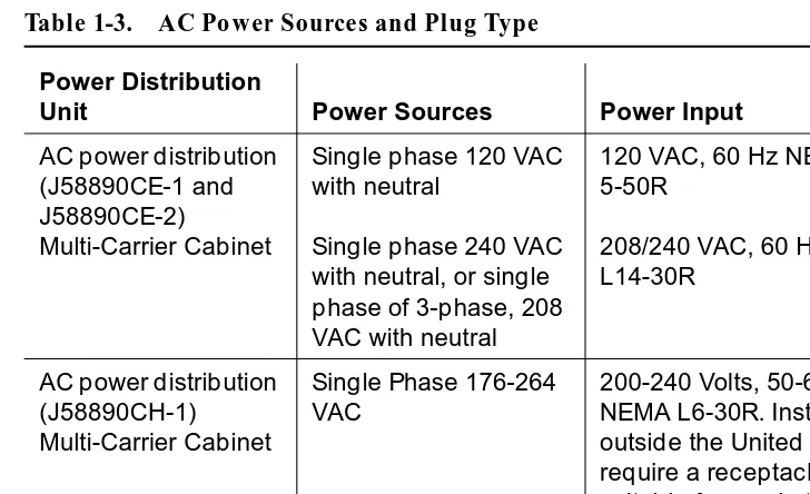
Table 1-3 describes the power sources and required AC input power.
NOTE:
The type of power required is shown on the cabinet’s rear door. Table 1-3. AC Power Sources and Plug Type
Power Distribution
Unit Power Sources Power Input
AC power distribution (J58890CE-1 and J58890CE-2) Multi-Carrier Cabinet
Single phase 120 VAC with neutral
Single phase 240 VAC with neutral, or single phase of 3-phase, 208 VAC with neutral
120 VAC, 60 Hz NEMA 5-50R
208/240 VAC, 60 Hz NEMA L14-30R
AC power distribution (J58890CH-1) Multi-Carrier Cabinet
Single Phase 176-264 VAC
Installation and Test for Multi-Carrier Cabinets 555-230-112 May 1998 Install and Connect Cabinets
Page 1-8 Connect AC Power and Ground
1
!
CAUTION:
The equipment room AC power and ground wiring must be performed by a qualified electrician. Refer to DEFINITY Enterprise Communications Server Release 6 System Description Pocket Reference, for site requirement information.
!
CAUTION:
The power circuit must be dedicated to the system and must not be shared with other equipment and must not be controlled by a wall switch. The AC receptacle should not be located under the MDF.
!
CAUTION:
System grounding must comply with the general rules for grounding contained in Article 250 of the National Electrical Code (NEC), National Fire Protection Agency (NFPA) 70, or the applicable electric code in the country containing the equipment. For more information, refer to ‘‘Approved Grounds’’ on page 1-23.
Connect Ground to AC-Powered System
(J58890CE)
Grounding is relatively simple for an AC-powered system. Basically, the cabinets connect to the single-point ground terminal block located at either the AC load center or to a separate single-point ground block wired to the AC load center (or optional AC protector cabinet).
■ The approved ground wire must be a green (or green with yellow stripe), 6 AWG (#40) (16 mm2), copper, stranded wire.
■ Bond all approved grounds at the single-point ground to form a single grounding electrode system.
AC Load Center is 50 Feet (15.2 m) or Less from
Cabinet
1. At the bottom rear of the PPN cabinet, connect a 6 AWG (#40) (16 mm2) CABINET GROUND wire to the cabinet ground terminal block. See Figure 1-1.
2. Route the CABINET GROUND wire to the single-point ground block at the AC load center and connect.
3. At the bottom rear of the first EPN cabinet (if provided), connect a 6 AWG (#40) (16 mm2) CABINET GROUND wire to the cabinet ground terminal block.
Installation and Test for Multi-Carrier Cabinets 555-230-112 May 1998 Install and Connect Cabinets
Page 1-9 Connect AC Power and Ground
1
NOTE:
If the EPN cabinet is located remote from the PPN cabinet (in a separate room or building), connect the CABINET GROUND wire to an approved ground.
Figure 1-1. Typical Cabinet Ground Location
5. Repeat connecting each EPN cabinet to the single-point ground block. Figure Notes
1. PPN Cabinet
2. EPN Cabinet (if Installed)
3. 6 AWG (#40) (16 mm2) CABINET GROUND Wire
4. Cabinet Ground Terminal Block
5. AC Load Center Single-Point Ground
6. Less than 50 Wire Feet (15.2 m)
7. 10 AWG (#25) (6 mm2) Ground Wire to CBC
widmgrnd LJK 092697
1 2 2
3
3 3
4 4 4
5
Installation and Test for Multi-Carrier Cabinets 555-230-112 May 1998 Install and Connect Cabinets
Page 1-10 Connect AC Power and Ground
1
6. At the AC load center, connect a 10 AWG (#25) (6 mm2) wire to the single-point ground block. This ground wire will later be tie-wrapped to the trunk cables and connected to the Coupled Bonding Conductor (CBC) ground block at the MDF.
AC Load Center is More Than 50 Feet (15.2 m)
from Cabinet
1. Mount the single-point ground block to any surface between the MCC cabinets and the AC load center single-point ground. The single-point ground block must be mounted to a non-metallic surface.
2. At the bottom rear of the PPN cabinet, connect a 6 AWG (#40) (16 mm2) CABINET GROUND wire to the cabinet ground block. See Figure 1-2.
3. Route the wire to the single-point ground block and connect.
4. At the first EPN cabinet (if provided), connect a 6 AWG (#40) (16 mm2) CABINET GROUND wire to the cabinet ground terminal block.
5. Route the CABINET GROUND wire to the single-point ground block and connect.
NOTE:
If the EPN cabinet is located remote from the PPN cabinet (in a separate room or building), route the EPN CABINET GROUND wire to an approved ground.
6. Repeat connecting each EPN cabinet to the single-point ground block.
7. Connect a 6 AWG (#40) (16 mm2) ground wire to an unused terminal on the single-point ground block.
Installation and Test for Multi-Carrier Cabinets 555-230-112 May 1998 Install and Connect Cabinets
Page 1-11 Connect AC Power and Ground
1
Figure 1-2. Typical Cabinet Grounding Wiring Diagram Figure Notes
1. PPN Cabinet
2. EPN Cabinet (if Installed)
3. 6 AWG (#40) (16 mm2) CABINET GROUND Wire
4. Single-Point Ground Block
5. 6 AWG (#40) (16 mm2) Ground Wire
6. AC Load Center Single-Point Ground
7. Over 50 Feet (15.2 m)
8. Cabinet Ground Terminal Block
6
1 2 2
3 3 3
5
widfspgb KLC 100297
7 4
Installation and Test for Multi-Carrier Cabinets 555-230-112 May 1998 Install and Connect Cabinets
Page 1-12 Connect AC Power and Ground
1
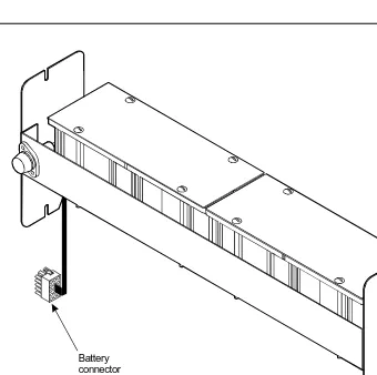
Connect Battery Leads (J58890CH-1)
Figure 1-3 shows a typical optional small battery holdover assembly. These assemblies may ship with the battery leads disconnected to prevent the batteries from discharging.
1. Plug the battery connector into the -48 VDC Batteries connector on the rear of the J58890CH-1 Power Distribution Unit.
Figure 1-3. Typical Small Battery Assembly
!
CAUTION:
Power is present in the cabinet even if the AC power cable is unplugged. Turn off the main circuit breaker on the front of the power distribution unit when procedures require ALL power to be removed from the cabinet.
psdfbatb RPY 061797
Installation and Test for Multi-Carrier Cabinets 555-230-112 May 1998 Install and Connect Cabinets
Page 1-13 Connect AC Power and Ground
1
Figure 1-4. Power Distribution Unit (J58890CH)
2. Be sure the main power to the power distribution unit is OFF.
3. At the power distribution unit, set all carrier circuit breakers OFF.
Small Battery Holdover
1. Connect the small battery holdover cable to J20. See Figure 1-4. Figure Notes
1. Connect small battery holdover cable (or temperature sensor cable from large battery cabinet) to J20
2. Carrier Circuit Breakers
3. Ground Terminal Block
4. Connect large battery holdover cable here
5. -48 VDC Return - 1/0 AWG (50 mm2) cable
6. -48 VDC - 1/0 AWG (50 mm2) cable
7. 1/0 AWG (50 mm2) 50 feet (15.2 m) cable to large battery cabinet. For cables greater than 50 feet (15.2 m), contact your Lucent Technologies representative.
8. Ground Terminal Block
Installation and Test for Multi-Carrier Cabinets 555-230-112 May 1998 Install and Connect Cabinets
Page 1-14 Connect AC Power and Ground
1
Large Battery Holdover
When using large battery holdover, 1 battery cabinet is required for every system cabinet requiring holdover. The 24-cell battery cabinet must have a float voltage of 54.2 VDC.
1. Connect the -48 VDC cable to the large battery connector. See Figure 1-4.
2. Connect the -48 VDC RETURN cable to the ground terminal block.
3. Connect the temperature sensor cable, from the battery cabinet, to J20.
NOTE:
An adapter cable may be required when connecting the temperature sensor cable to the J58890CH unit. See Table 1-4.
Connect Shorting Cable to J58890CE-2
!
CAUTION:
For a cabinet with a battery charger, read the caution label on the 397C battery charger before disconnecting batteries.
Some cabinets contain a J58890CE-2 AC Power Distribution Unit without an optional battery charger. Install the shorting cable only when a battery charger is
not installed.
Table 1-4. Temperature Sensor Cable Adapter Cables
H600-476 Adapter Cable Usage
Group 1 (G1) 24-cell customer-provided battery
Group 3 (G3) (included with battery cabinet)
Installation and Test for Multi-Carrier Cabinets 555-230-112 May 1998 Install and Connect Cabinets
Page 1-15 Connect AC Power and Ground
1
Figure 1-5. Shorting Cable Installation
1. Set the circuit breakers on the power distribution unit OFF. See Figure 1-5.
2. At the rear of the cabinet, insert the shorting cable (H600-442-G1) into J11. The cable is keyed so it can fit only 1 way.
Connect AC Power
1. Set the main circuit breakers on the power distribution unit OFF.
2. Connect cabinet AC line cords to the AC power receptacles.
3. Do not power up the system at this time. Figure Notes
1. Shorting Cable (H600-442-G1) (If Battery Charger is Not Installed)
Installation and Test for Multi-Carrier Cabinets 555-230-112 May 1998 Install and Connect Cabinets
Page 1-16 Connect DC Power and Ground
1
Connect DC Power and Ground
Power Distribution Unit (J58890CH-1 Only)
Rectifier Modules and Battery Interface Unit
Each rectifier module operates as an integral part of a complete power system with battery backup. The modules operate in a redundant, high reliability mode to provide -48 VDC at 850 Watts to a common power bus.
The Battery Interface Unit (BIU) controls the rectifier modules, manages the batteries, and reports the status of system power. The BIU provides the Remote Power Off (RPO) option and battery alarm interfaces for internal and external alarms.
Figure 1-6. Rectifier Module Installation Figure Notes
1. Install Battery Interface Unit into Slot 1
2. Install Rectifier Modules into Slots 2-5
3. Rectifier Module 3 (in Slot 4)
4. Test Points
Installation and Test for Multi-Carrier Cabinets 555-230-112 May 1998 Install and Connect Cabinets
Page 1-17 Connect DC Power and Ground
1
1. Install the BU3200A Battery Interface Unit (comcode 107781502) in the first slot of the power distribution unit. See Figure 1-6.
NOTE:
The BIU and the rectifier modules are keyed and can only install 1 way.
2. Install the first 2 RM0850HA100 Rectifier Modules (comcode 107793796) into the second and third slots of the power distribution unit.
3. If 2 to 3 carriers are installed in the system, install a third rectifier module (N+1).
4. If 4 to 5 carriers are installed in the system, install a fourth rectifier module.
5. The fifth rectifier module slot is reserved for future system growth.
Connect Power
1. Have a qualified electrician connect and route wires from the AC load center to the dedicated electrical outlet for the power distribution unit.
Connect PPN Cabinet Ground
1. Connect 1 end of a 10 AWG (#25) (6 mm2) wire to the ground terminal block on the rear of the cabinet. See Figure 1-4.
2. Route the wire to the Coupled Bonding Conductor (CBC), or to an approved ground, and connect.
3. Connect 1 end of a 6 AWG (#40) (16 mm2) CABINET GROUND wire to the ground terminal block at the rear of the cabinet.
4. Route the CABINET GROUND wire to the AC load center single-point ground block and connect.
Connect EPN Cabinet Ground(s)
1. Connect 1 end of a 6 AWG (#40) (16 mm2) CABINET GROUND wire to the ground terminal block at the bottom rear of the EPN cabinet. See Figure 1-2.
2. Route the CABINET GROUND wire to the AC load center single-point ground and connect.
Installation and Test for Multi-Carrier Cabinets 555-230-112 May 1998 Install and Connect Cabinets
Page 1-18 Connect DC Power and Ground
1
DC Power and Ground (J58890CF Only)
Figure 1-7 shows a typical power and ground layout for a DC-powered cabinet. The size of the wire required for the -48 volt DC and -48 volt return must ensure the -48 volt DC supplied by the battery plant is maintained between -42.5 and -54.2 volts DC at all times for proper operation and to prevent hardware damage. This procedure applies to both PPN and EPN cabinets.
Installation and Test for Multi-Carrier Cabinets 555-230-112 May 1998 Install and Connect Cabinets
Page 1-19 Connect DC Power and Ground
1
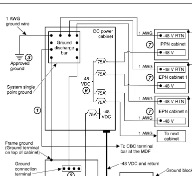
Connect DC Power and Ground
The grounding methods for the DC-powered system are more complex than that of an AC-powered system. The following installation procedures refer to Figure 1-7. The numbers 1-8 in Figure 1-7 match the following subsections 1-8. Other figures may be referenced as required.
!
CAUTION:
Grounding of the system shall comply with the general rules for grounding contained in Article 250 of the National Electrical Code, NFPA 70. For more information, refer to ‘‘Approved Grounds’’ on page 1-23.
1. Install Coupled Bonding Conductor Wires
This is a conductor that connects to the single-point ground block and run adjacent to pairs in an associated cable. The mutual coupling between the CBC and the pairs reduces potential differences in terminating equipment. The conductor consists of a 10 AWG (#25) (6 mm2) wire terminated at the CBC ground terminal bar at the Main Distribution Frame (MDF).
1. At the DC Power Cabinet, connect a 10 AWG (#25) (6 mm2) ground wire to the Ground Discharge Bar. See Figure 1-7.
2. Route the 10 AWG (#25) (6 mm2) ground wire to the CBC ground terminal bar at the MDF. Be sure a minimum of 12 inches (30.5 cm) spacing is maintained between the CBC and other power and ground leads.
3. Tie wrap the ground wire to the inside wiring cable.
NOTE:
The ground wires are connected to the CBC as instructed in Chapter 2, ‘‘Install Telecommunications Cabling’’.
2. Connect DC Battery and Power Cabinet
Grounds
1. Measure and cut a 6 AWG (#40) (16 mm2) wire (comcode 846110971) long enough to reach between the ground connection terminal in the DC Battery Cabinet and the Ground Discharge Bar in the DC Power Cabinet. See Figure 1-7.
2. Crimp terminal lugs on each end of the wire. Terminal lugs are furnished as part of D-181895, Kit of Parts (comcode 105434559).
3. At the DC Power Cabinet, connect the wire to the Ground Discharge Bar.
Installation and Test for Multi-Carrier Cabinets 555-230-112 May 1998 Install and Connect Cabinets
Page 1-20 Connect DC Power and Ground
1
3. DC Power Cabinet Approved Ground
1. At the DC Power Cabinet, connect a 1 AWG (#70) (44 mm2) ground wire to the Ground Discharge Bar. See Figure 1-7.
2. Route the ground wire out of the cabinet and terminate it on the approved ground. The approved ground must be identified with a grounding tag (FORM 15657NR or equivalent). See ‘‘Approved Grounds’’ on page 1-23.
4. Connect Main AC Supply to DC Power Cabinet
1. Have a qualified electrician connect AC power leads to the rectifiers in the DC Power Cabinet. Each rectifier should have its own branch circuit. Terminate the leads on the AC INPUT terminal block of each rectifier.
2. Ensure the associated circuit breakers at the AC power panel are OFF.
5. Connect Ground Wires for DC-Powered
Systems
!
CAUTION:
Do not connect any ground wires from an EPN cabinet to another EPN cabinet or to a PPN cabinet. All ground wires must be terminated at the single-point ground block at the main AC supply (AC mains).
1. Connect a 6 AWG (#40) (16 mm2) wire to the PPN cabinet ground terminal block.
2. Route the wire to the AC mains single-point ground block and connect.
3. Connect a 6 AWG (#40) (16 mm2) wire to each EPN’s cabinet ground terminal block.
4. Route the wire(s) to the AC mains single-point ground block and connect.
6. Turn Circuit Breakers Off
The main circuit breaker on a DC-powered PPN/EPN cabinet is located on the front of the power distribution unit. The circuit breakers on the rear of the power distribution unit control the individual carriers. See Figure 1-4 for the location of the carrier breakers.
1. Set the main circuit breaker to OFF.
Installation and Test for Multi-Carrier Cabinets 555-230-112 May 1998 Install and Connect Cabinets
Page 1-21 Connect DC Power and Ground
1
7. Connect DC Power to PPN and EPN Cabinets
1. Be sure the main circuit breaker is OFF.
2. Measure and cut a piece of 6 AWG (#40) (16 mm2) wire long enough to reach from the DC Power Cabinet to the PPN cabinet.
3. At the DC Power Cabinet, connect the -48 volt DC wire to the DC OUTPUT circuit breaker. See Figure 1-7. Connect the -48 volt RTN (return) wire to the ground discharge bar.
4. Route the wires out of the cabinet, through the hole in the lower rear cover, and to the PPN cabinet.
5. Connect the -48 volt DC wire to the -48VDC terminal on the J58890CF Power Distribution Unit.
6. Connect the -48 volt RTN wire to the -48RTN terminal on the J58890CF Power Distribution Unit terminal block.
7. Repeat Steps 2 through 6 for each EPN and Auxiliary cabinet in the system.
8. Connect DC Battery Cabinet to DC Power
Cabinet
!
CAUTION:
When using battery backup, each cabinet in the system must have a dedicated battery backup. The battery backup power cannot be shared between cabinets.
1. Set the main circuit breaker on the DC Battery Cabinet and the DC Power Cabinet to OFF.
2. Measure and cut a 6 AWG (#40) (16 mm2) wire long enough to reach from the DC Battery Cabinet’s -48 Volt DC terminal to a DC OUTPUT circuit breaker on the DC Power Cabinet.
3. At the DC Battery Cabinet, connect the -48 volt DC wire to the -48 VDC connector. Connect the -48 volt RTN wire to the ground connection terminal.
4. Route the wires out of the cabinet through the hole in the lower rear cover and to the DC Power Cabinet.
Installation and Test for Multi-Carrier Cabinets 555-230-112 May 1998 Install and Connect Cabinets
Page 1-22 Connect DC Power and Ground
1
Mixed AC/DC Power and Ground
Figure 1-8 shows a power and ground layout for a mixed AC/DC-powered
cabinet configuration in the same equipment room with the PPN being DC powered and the EPN being AC powered. If a second EPN is part of the system, use the same basic connections shown in Figure 1-8.
Figure 1-8. Typical Power and Ground for a Mixed AC/DC-Powered Cabinet Approved
ground
1/0 AWG (50 mm ) up to 50 feet (15.2 m) or engineered for less than 0.5 voltage drop per conductor
2
To AC power
source
EPN cabinet AC power cord
AC power-distribution
unit
Cabinet Ground Block -48V -48V RTN
PPN cabinet 75A
-48V
DC power supply System
single-point ground
Coupled Bonding Conductor
To CBC terminal block at MDF
cydfacdc RPY 021798
Ground discharge
Installation and Test for Multi-Carrier Cabinets 555-230-112 May 1998 Install and Connect Cabinets
Page 1-23 Approved Grounds
1
Approved Grounds
An approved ground is the closest acceptable medium for grounding the building entrance protector, entrance cable shield, or single-point ground of electronic telephony equipment. If more than 1 type of approved ground is available on the premises, the grounds must be bonded together as required in Section 250-81 of the National Electrical Code.
Grounded Building Steel
—
The metal frame of the building where it iseffectively grounded by 1 of the following grounds: acceptable metallic water pipe, concrete encased ground, or a ground ring.
Acceptable Water Pipe
—
A metal underground water pipe, at least 1/2-inch(1.3 cm) in diameter, in direct contact with the earth for at least 10 feet (3 m). The pipe must be electrically continuous (or made electrically continuous by bonding around insulated joints, plastic pipe, or plastic water meters) to the point where the protector ground wire connects. A metallic underground water pipe must be supplemented by the metal frame of the building, a concrete encased ground, or a ground ring. If these grounds are not available, the water pipe ground can be supplemented by 1 of the following types of grounds:
■ Other local metal underground systems or structures
—
Local underground structures such as tanks and piping systems■ Rod and pipe electrodes
—
A 5/8-inch (1.6 cm) solid rod or 3/4-inch (2 cm) conduit or pipe electrode driven to a minimum depth of 8 feet (2.4 m).■ Plate electrodes
—
Must have a minimum of 2 square feet (0.185 square m) of metallic surface exposed to the exterior soilConcrete Encased Ground
—
An electrode encased by at least 2 inches(5.1 cm) of concrete and located within and near the bottom of a concrete foundation or footing in direct contact with the earth. The electrode must be at least 20 feet (6.1 m) of 1 or more steel reinforcing bars or rods 1/2-inch (1.3 cm) in diameter, or at least 20 feet (6.1 m) of bare, solid copper, 4 AWG (26 mm2) wire.
Ground Ring
—
A buried ground that encircles a building or structure at a depthInstallation and Test for Multi-Carrier Cabinets 555-230-112 May 1998 Install and Connect Cabinets
Page 1-24 Approved Grounds
1
Approved Floor Grounds
Approved floor grounds are those grounds on each floor of a high-rise building suitable for connection to the ground terminal in the riser closet and to the cabinet equipment single-point ground terminal. Approved floor grounds may include the following:
■ Building steel
■ The grounding conductor for the secondary side of the power transformer feeding the floor
■ Metallic water pipes
■ Power feed metallic conduit supplying panel boards on the floor ■ A grounding point specifically provided in the building for the purpose
!
WARNING:
Installation and Test for Multi-Carrier Cabinets 555-230-112 May 1998 Install and Connect Cabinets
Page 1-25 Connect Remote Power Off Cable and External Alarm Cable
1
Connect Remote Power Off Cable and
External Alarm Cable
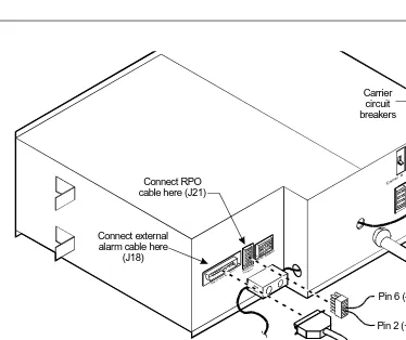
Figure 1-9 shows the location of the Remote Power Off (RPO) cable. The opposite end of the cable connects to the Emergency Power Off (EPO) switch located outside of the equipment room.
Figure 1-9. Remote Power Off Cable Connections
—
Part 1Even though the equipment room EPO switch disconnects main AC power to the equipment room, it cannot disconnect the battery power from the J58890CH. An auxiliary set of contacts inside the EPO are used for this function.
1. Plug the RPO cable into the connector shown in Figure 1-9.
2. Route the opposite end of the wires to the EPO switch. The opposite end of the RPO cable connects to the internal relay.
NOTE:
The EPO switch and the auxiliary contacts (inside the EPO switch assembly) are customer-provided.
Connect RPO cable here (J21)
Connect external alarm cable here
(J18)
Carrier circuit breakers
psdf002 CJL 081596
External alarm cable
Pin 6 (-RPO)
Installation and Test for Multi-Carrier Cabinets 555-230-112 May 1998 Install and Connect Cabinets
Page 1-26 Connect Remote Power Off Cable and External Alarm Cable
1
!
CAUTION:
The auxiliary contacts inside the EPO switch assembly must close when the switch is pressed. This contact closure energizes the relay inside the power distribution unit, causing the connection to the battery holdover assembly to open.
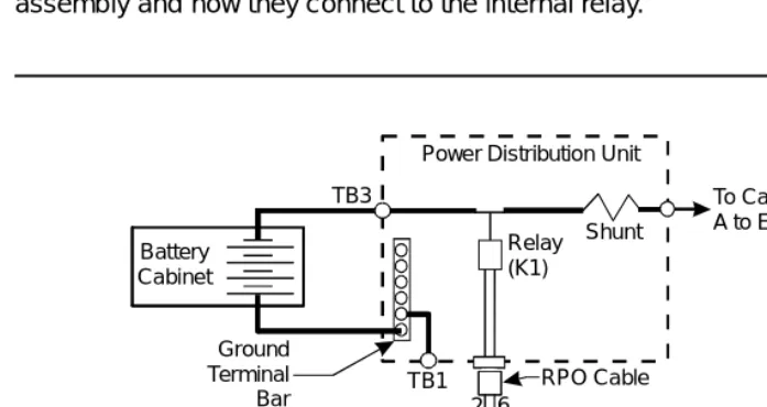
Figure 1-10 shows the cabling from the auxiliary contacts inside the EPO switch assembly and how they connect to the internal relay.
Figure 1-10. Remote Power Off Cable Connections
—
Part 21. Connect the RPO wires to the auxiliary contacts on the EPO switch. See
Figure 1-10.
NOTE:
The EPO switch and the auxiliary contacts for the RPO connection are customer-supplied.
Ground Terminal Bar
Shunt
RPO Cable Power Distribution Unit
TB1
To Carriers A to E TB3
Auxiliary Contacts in EPO Switch
2 6 Battery
Cabinet
0026_3 RBP 080196
Installation and Test for Multi-Carrier Cabinets 555-230-112 May 1998 Install and Connect Cabinets
Page 1-27 Connect External Alarm Cable
1
Connect External Alarm Cable
1. Plug the external alarm cable into the connector shown in Figure 1-9.
2. Route the opposite end of the cable to the MDF. The alarm cable is connected to the MDF in Chapter 5, ‘‘Install and Wire Telephones and Other Equipment’’.
Connect AC Power to Stratum 3 Clock
Cabinet
The clock cabinet requires a 120 VAC, 15 Amp receptacle. The green wire ground provided by the receptacle is sufficient. The clock cabinet does not require a ground connection back to the single-point ground.
Check Commercial Power and Connect AC Power
Before powering up the system, check the AC power using a KS-20599 digital voltmeter (DVM) (or equivalent).
1. Set the DVM to the 250 volt range.
2. Carefully measure the voltage between the hot and neutral side of the receptacle. The neutral wire is white, the hot wire is black.
3. Verify the meter reads 106 to 128 VAC. If not, have a qualified electrician correct the problem.
4. Measure the voltage between the neutral and ground side of the receptacle. The ground wire is green.
5. Verify the meter reads 0 VAC. If not, have a qualified electrician correct the problem.
Installation and Test for Multi-Carrier Cabinets 555-230-112 May 1998 Install and Connect Cabinets
Page 1-28 Connect DC Power and Ground to Stratum 3 Clock Cabinet
1
Connect DC Power and Ground to
Stratum 3 Clock Cabinet
1. Provide power for the clock cabinet from the same DC power plant as the DEFINITY System.
2. Ground the clock cabinet to the DC power plant.
Connect Clock Cabinet Grounding
1. Measure and cut a 6 AWG (#40) (16 mm2) wire long enough to reach from the clock cabinet to the ground discharge bar in the DC power plant.
2. Insert 1 end of the wire into the ground lug on the clock cabinet and tighten the screw.
3. Attach the lug to the receptacle cover. Be sure the lug and cabinet ground wires are connected to separate screws on the receptacle cover.
4. Route the ground wire to the DC power plant and connect to DISCH GRD inside the cabinet.
Connect Stratum 3 Clock DC Power
1. Set the clock cabinet circuit breaker at the DC power plant OFF.
2. At the clock cabinet, connect a 6 AWG (#40) (16 mm2) ground wire to the -48V terminal on the terminal strip.
3. At the clock cabinet, connect a 6 AWG (#40) (16 mm2) wire to the -48VRTN terminal on the terminal strip.
4. Route the wires out of the cabinet and to the DC power plant.
5. At the DC power plant, connect the -48V wire to the DC OUTPUT circuit breaker.
Installation and Test for Multi-Carrier Cabinets 555-230-112 May 1998 Install and Connect Cabinets
Page 1-29 Fiber Optic Interconnect Cabling
1
Fiber Optic Interconnect Cabling
Signals between the cabinets are carried by fiber optic cables. Lightwave transceivers provide the required fiber optic interface.
The fiber optic cables from the DEFINITY System route to a Lightguide Interconnect Unit (LIU) or fiber optic shelf. Refer to Appendix A, ‘‘Connecting Fiber Optic Cables’’. Refer to this information for fiber optic equipment comcode numbers, connecting to LIUs or shelves, and routing through lightguide
equipment.
Use multi-mode fiber transceivers and multi-mode fiber optic cables between cabinets unless single-mode fiber is required (distance restrictions). Use metallic cables between carriers.
!
CAUTION:
The DEFINITY ECS may contain a Class 1 LASER device if single-mode fiber optic cable is connected to a remote Expansion Port Network (EPN). The LASER device operates within the following parameters:
■ Maximum Power Output: -5 dBm ■ Wavelength: 1310 nm
■ Mode Field Diameter: 8.8 microns
CLASS 1 LASER PRODUCT IEC 825 1993
!
CAUTION:
Use of controls or adjustments or performance of procedures other than those specified herein may result in hazardous radiation exposure.
Installation and Test for Multi-Carrier Cabinets 555-230-112 May 1998 Install and Connect Cabinets
Page 1-30 Fiber Optic Interconnect Cabling
1
Connect Fiber Optic Cables
NOTE:
Always use the Cable Running List that accompanies the system when installing fiber optic cables. The following procedure is a typical example of how to cable a system.
If the cabinets are close together, the signal may go through a single, directly- connected fiber optic cable. If the cabinets are far apart, it may be easier to connect the cabinets through an LIU or fiber shelf.
For each fiber indicated in the fiber optic Cable Running List:
1. Install a lightwave transceiver on the cabinet connector at the position in the FROM column in the running list.
2. Select a cable indicated by the CABLE CODE and LENGTH in the running list. Connect 1 of the fibers to each connector on the lightwave
transceivers just installed. The fiber is numbered 1 or 2. The connector on the transceiver is labeled TX or RX. Keep track of which fiber connects to which transceiver connector. Label both ends of these cables.
3. Route the fiber optic cables from the transceiver out of the cabinet. Secure the cables to the cable-tie rack. Keep the fiber optic cables clear of the heavier I/O cables.
4. If the cabinet in the TO column in the running list is located remotely from the FROM cabinet, connect to the TO cabinet by way of the LIU.
5. Install a lightwave transceiver on the cabinet connector at the position in the TO column in the running list.
6. Route the cables from the FROM cabinet down into the cable trays of each EPN cabinet. Connect the cables to the lightwave transceiver just installed on the TO cabinet.
7. Connect the fiber that comes from the TX connector of the FROM transceiver to the RX connector of the TO transceiver and vice versa.
Installation and Test for Multi-Carrier Cabinets 555-230-112 May 1998 Install and Connect Cabinets
Page 1-31 Fiber Optic Interconnect Cabling
1
CSS-Connected System with 1 Switch Node
Standard-Reliability
Figure 1-11 shows typical fiber optic cabling between cabinets. The cable between the EI and SNI on the PPN is a pre-installed metallic cable (H600-278).
1. If no running list is available, use the outer slots first in alternating order. Connect the first 2 SNI slots to 3 and 20 (the leftmost and rightmost of the unused slots). Next, use 4 and 19, and so forth.
2. Add links to the EPNs in alternating order (20, 3, 19, 4, 18, 5, and so forth).
Figure 1-11. Standard Reliability CSS-Connected Release 6r with 1 Switch Node
Figure Notes
1. Cabinet 1 (PPN with 1 Switch Node)
2. Cabinet 2 through 16 (EPN)
3. H600-278 Metallic Cable
Installation and Test for Multi-Carrier Cabinets 555-230-112 May 1998 Install and Connect Cabinets
Page 1-32 Fiber Optic Interconnect Cabling
1
High-Reliability
Figure 1-12 shows typical fiber optic cabling between cabinets. The cable between the EI and SNI on the PPN cabinet is a pre-installed metallic cable (H600-278).
1. Connect the cables between the PPN cabinet and each EPN cabinet in an alternating port slot order: 3, 19; 4, 18; 5, 17; and so forth. Cabinet 1 is a Release 6r PPN with 1 Switch Node.
Figure 1-12. High-Reliability CSS-Connected with 1 Switch Node Figure Notes
1. Cabinet 1 (PPN with 1 Switch Node)
2. Cabinet 2 through 15 (EPN)
3. H600-278 Metallic Cable
Installation and Test for Multi-Carrier Cabinets 555-230-112 May 1998 Install and Connect Cabinets
Page 1-33 Fiber Optic Interconnect Cabling
1
Critical Reliability
Figure 1-13 shows typical fiber optic cabling between cabinets. The cable between port slots 1 and 2 on each switch node is a metallic cable (H600-278).
1. Connect the 2 groups of 1 to 15 cables between the PPN and each EPN in an alternating port slot order: 20, 3; 19, 4; 18, 5; and so forth.
Figure 1-13. Critical-Reliability CSS-Connected with 1 Switch Node
2. Both connections from each EPN must go to the same slot number. For example: EPN cabinet 2, 2A1 to 1E3 and cabinet 2, 2B2 to 1D3.
Figure Notes
1. Cabinet 1 (PPN with 1 Duplex Switch Node)
2. Cabinet 2 through 16 (EPN)
3. H600-278 Metallic Cable
Installation and Test for Multi-Carrier