Notice
Every effort was made to ensure that the information in this book was complete and accurate at the time of printing. However, information is subject to change.
Federal Communications Commission
(FCC) Interference Notice
This equipment has been tested and found to comply with the limits of a Class A or a Class B digital device, pursuant to Part 15 of FCC rules. For additional information on FCC regulations, see “Federal Communications Commission (FCC) Interference Information” on the next page.
Canadian Emissions Requirements
This digital apparatus does not exceed the Class A or the Class B limits for radio noise emissions from digital apparatus set out in the Radio Interference Regulations of the Industry Canada (IC). For additional IC information, see “IC Notification and Repair Information” in this section.
Le present appareil numerique n’emet pas de bruits radioelectriques depassant les limites applicables aux appareils numeriques de la classe A ou de la classe B prescrites dans le Reglement sur le brouillage radioelectrique edicte par le ministere des Industrie Canada. Vous trouverez des renseignements complémitaires dans cette section.
Security
Toll fraud, the unauthorized use of your telecommunications system by an unauthorized party (for example, persons other than your company’s employees, agents, subcontractors, or persons working on your company’s behalf) can result in substantial additional charges for your
telecommunications services. You are responsible for the security of your system. There may be a risk of toll fraud associated with your telecommunications system. You are responsible for
programming and configuring your equipment to prevent unauthorized use. Your system manager should read all documents provided with this product to fully understand the features that can introduce the risk of toll fraud and the steps that can be taken to reduce that risk. Lucent
Technologies does not warrant that this product is immune from or will prevent unauthorized use of common-carrier telecommunication services or facilities accessed through or connected to it. Lucent Technologies will not be responsible for any charges that result from such unauthorized use. If you suspect you are being victimized by toll fraud and you need technical support or assistance, call the Lucent Technologies National Customer Care Center at
1 800 628-2888.
Trademarks
Call the hotline at 1 800 628-2888 or your Lucent Technologies Authorized Dealer. If you need assistance when programming or using your system. Consultation charges may apply.
Warranty
Lucent Technologies provides a limited warranty for this product. Refer to “Lucent Technologies Limited Warranty and Limitation of Liability” in Appendix B of this book.
Ordering Information
Interference Information
References to FCC regulations are not applicable outside of the U.S.
Class A Compliance
This equipment, in the 5-Slot configuration and in the 2-Slot configuration with a 308EC module or PARTNER MAIL VS, has been tested and found to comply with the limits for a Class A digital device, pursuant to Part 15 of FCC rules.
These limits are designed to provide reasonable protection against harmful interference when the equipment is operated in a commercial environment. This equipment
generates, uses, and can radiate radio frequency energy and, if not installed and used in accordance with the instruction manuals, may cause harmful interference to radio communications. Operation of this equipment in a residential area is likely to cause harmful interference, in which case the user will have to correct the interference at his or her own expense.
Class B Compliance
The Standalone PARTNER ACS processor module configuration and the 2-Slot configuration using a 200, a 206, or a 400 module have been tested and found to comply with the limits for a Class B digital device, pursuant to Part 15 of FCC rules.
These limits are designed to provide reasonable protection against harmful interference when the equipment is operated in a residential environment. This equipment
generates, uses, and can radiate radio frequency energy and, if not installed and used in accordance with the instruction manuals, may cause harmful interference to radio communications.
FCC Notification and Repair Information
This equipment is registered with the FCC in accordance with Part 68 of its rules. In compliance with those rules, you are advised of the following:
Means of Connection: Connection to the telephone network shall be through a
standard network interface jack USOC RJ11C. These USOCs must be ordered from your local telephone company.
FCC compliant line cords are provided with Line and Line/Extension Modules for connecting to the telephone company provided USOC RJ11C jacks. Use only FCC compliant line cords and jacks for these connections.
— The telephone number(s) you will be using with this equipment.
— The appropriate registration number and ringer equivalence number (REN) which can be found on the right hand side of the control unit.
— The facility interface code, which is O2LS2.
You must also notify your local telephone company if and when this equipment is permanently disconnected from the line(s).
REN Information: The REN is used to determine the quantity of devices which may be
connected to the same telephone line. Excessive RENs on the telephone line may result in the devices not ringing in response to incoming call. In most, but not all areas, the sum of RENs should not exceed five (5.0). To be certain of the number of devices that may be connected to a line, as determined by the total RENs, contact the local telephone company.
Repair Instructions: If you experience trouble because your equipment is
malfunctioning, the FCC requires that you disconnect the equipment from the network and not use it until the problem has been corrected. Repairs to this equipment can only be made by the manufacturer, its authorized agents, or by others who may be
authorized by the FCC. In the event repairs are needed on this equipment, please contact the Lucent Technologies hotline at 1 800 628-2888 or your local Authorized Dealer. For warranty information, see Appendix B.
Rights of the Local Telephone Company: If this equipment causes harm to the
telephone network, the local telephone company may discontinue your service temporarily. If possible, they will notify you in advance. But if advance notice is not practical, you will be notified as soon as possible. You will also be advised of your right to file a complaint with the FCC.
Your local telephone company may make changes in its facilities, equipment, operations, or procedures that affect the proper functioning of this equipment. If they do, you will be notified in advance to give you an opportunity to maintain uninterrupted telephone service.
Hearing Aid Compatibility: All system phones are compatible with inductively coupled
hearing aids as prescribed by the FCC.
Industry Canada (IC) Notification and Repair Information
The Industry Canada (IC) label identifies certified equipment. This certification means that the equipment meets certain telecommunications network protective, operational, and safety requirements. The IC does not guarantee the equipment will operate to the user’s satisfaction.
Users should ensure for their own protection that the electrical ground connections of the power utility, telephone lines, and internal metallic water pipe system, if present, are connected. This precaution may be particularly important in rural areas.
!
CAUTION:
Users should not attempt to make such connections themselves, but should contact the appropriate electrical inspection authority or electrician, as appropriate.
To prevent overloading, the Load Number (LN) assigned to each terminal device denotes the percentage of the total load to be connected to a telephone loop used by the device. The termination on a loop may consist of any combination of devices subject only to the requirement that the total of the Load Numbers of all the devices does not exceed 100.
IC Certification No: See the label on the side of the control unit.
CSA Certification No: LR 60486
Load No: 7
Renseignements sur la notification du ministére des Industrie Canada et la réparation
L’étiquette du ministére des Industrie Canada identifie le matériel homologué. Cette étiquette certifie que le matériel est conforme à certaines normes de protection, d’exploitation et de sécurité des réseaux de télécommunications. Le Ministére n’assure toutefois pas que le matériel fonctionnera à la satisfaction de l’utilisateur.
Avant d’installer ce méteriel, l’utilisateur doit s’assurer qu’il est permis de le raccorder aux installations de l’entreprise locale de télécommunication. Le matériel doit
également être installé en suivant une méthode acceptée de peuvent etre prolonges au moyen d’un dispositif homologue de raccordement. Dans certains cas, les fils intérieurs de l’enterprise utilisés pour un service individuel à ligne unique peuvent être prolongés au moyen d’un dispositif homologué de raccordement (cordon prolongateur
téléphonique interne). L’abonné ne doit pas oublier qu’il est possible que la conformité aux conditions énoncées ci-dessus n’empêchent pas la dégradation du service dans certaines situations. Actuellement, les entreprises de télécommunication ne permettent pas que l’on raccorde leur méteriel à des jacks d’abonné, sauf dans les cas précis prévus pas les tarifs particuliers de ces entreprises.
Les réparations de matériel homologué doivent être effectuées par un centre d’entretien canadien autorisé désigné par le foumisseur. La compagnie de
!
ADVERTISSEMENT:
L’utilisateur ne doit pas tenter de faire ces raccordements lui-même; il doit avoir racours à un service d’inspection des installations électriques, ou à un electrician, selon le cas.
L’indice de charge (IC) assigné à chaque dispositif terminal indique, pour éviter toute surcharge, le pourcentage de la charge totale qui peut être raccordée a un circuit téléphonique boucié utilisé par ce dispositif. La terminaison du circuit boucié peut être constituêe de n’importe quelle combinaison de dispositifs, pourvu que la somme des indices de charge de l’ensemble des dispositifs ne dépasse pas 100.
No d’homolagation: Voir l’étiquette sur le côté de l’unité de contrôle.
No de certification CSA: LR 60486
About This Guide
ix■ Purpose ix
■ Important Safety Instructions 1-ii
Overview
1-1■ Features and Capabilities 1-1
■ System Components 1-3
■ Auxiliary Equipment 1-13
Programming
2-1■ Overview 2-1
■ Hardware Considerations 2-2 ■ Initial System Setup 2-4 ■ Changing Settings after Installation 2-7 ■ Changing Settings to Support
PBX or Centrex Services 2-10
■ System Programming Options 2-11 ■ Using System Programming 2-19 ■ Upgrading from PARTNER
ACS Release 1.0 to Release 1.1 or
Release 2.0 or Later 2-24
■ Telephone Programming Options 2-24 ■ Using Telephone Programming 2-28
Learning About Telephones
3-1■ System Telephones 3-1
■ Standard Telephones 3-8
■ Combination Extensions 3-12
Using Auxiliary Equipment
4-1■ Overview 4-1
■ Answering Machines 4-3
■ Auto Attendant 4-7
■ Call Reporting Devices (SMDR) 4-9 ■ Contact Closure Devices 4-13 ■ Credit Card Scanners 4-14
■ Fax Machines 4-15
■ Modems 4-21
■ Night Service with Auxiliary Equipment 4-24 ■ Voice Messaging Systems 4-25
Feature Reference
5-1■ Overview 5-1
■ AA (Automated Attendant) Extensions (#607) 5-4 ■ Abbreviated Ringing (#305) 5-5 ■ Account Code Entry (F12) 5-6 ■ Allowed List Assignments (#408) 5-9 ■ Allowed Phone Number Lists (#407) 5-10
■ Answering Calls 5-13
■ Auto Dialing 5-16
■ Automatic Extension Privacy (#304) 5-19 ■ Automatic Line Selection 5-21 ■ Automatic System Answer Button
(#111)—Release 2.0 or Later 5-23 ■ Automatic System Answer Delay
(#110)—Release 2.0 or Later 5-26 ■ Automatic System Answer Lines
(#204)—Release 2.0 or later 5-28 ■ Automatic System Answer Mode
(#121)—Release 2.0 or Later 5-30 ■ Automatic System Answer Record/Playback
■ Backup Programming—Manual (#124) 5-42 ■ Call Coverage
(F20,XX,XX)—Release 2.0 or Later 5-44
■ Call Coverage Rings
(#116)—Release 2.0 or Later 5-48
■ Call Forwarding/Call Follow-Me (F11,XX,XX) 5-49
■ Call Park 5-52
■ Call Pickup (I6XX) 5-54
■ Call Waiting (#316) 5-56
■ Caller ID 5-58
■ Caller ID Inspect (F17) 5-61 ■ Caller ID Log Answered Calls
(#317)—Release 2.0 or Later 5-63
■ Caller ID Call Log Line Association
(#318)—Release 2.0 or Later 5-65
■ Caller ID Call Logging and Dialing
(F23)—Release 2.0 or Later 5-67
■ Caller ID Log All Calls
(#319)—Release 2.0 or Later 5-74
■ Caller ID Name Display (F16) 5-76 ■ Caller ID Type (#122) 5-77 ■ Calling Group Extensions (#502) 5-79
■ Conference Calls 5-81
■ Conference Drop (F06) 5-83 ■ Contact Closure (F41 and F42) 5-84 ■ Contact Closure Group (#612) 5-86 ■ Contact Closure Operation Type (#613) 5-88 ■ Copy Settings (#399) 5-90
■ Dial Mode (#201) 5-92
■ Direct Extension Dial Button
(#113)—Release 2.0 or Later 5-93
■ Direct Extension Dial Delay
(#112)—Release 2.0 or Later 5-96
■ Direct Extension Dial Lines
(#205)—Release 2.0 or Later 5-98
■ Direct Extension Dial Record/Playback
(I892)—Release 2.0 or Later 5-100
■ Display 5-111 ■ Display Language (#303) 5-113 ■ Distinctive Ring (#308) 5-114 ■ Do Not Disturb (F01) 5-115 ■ Doorphone Alert Extensions (#606) 5-117 ■ Doorphone Extension (#604 and #605) 5-119 ■ Emergency Phone Number List (#406) 5-121 ■ Exclusive Hold (F02) 5-123 ■ Extension Name Display 5-125 ■ External Hotline (#311) 5-127 ■ Fax Machine Extensions (#601) 5-130 ■ Forced Account Code Entry (#307) 5-131 ■ Forced Account Code List (#409) 5-133 ■ Group Call Distribution (#206) 5-135 ■ Group Calling—Ring/Page (I7G/I*7G) 5-137 ■ Group Hunting—
Ring/Voice Signal (I77G/I*77G) 5-141
■ Group Pickup (I66G) 5-145
■ Hold 5-147
■ Hold Disconnect Time (#203) 5-149
■ Hotline (#603) 5-151
■ Hunt Group Extensions (#505) 5-153 ■ Intercom Dial Tone (#309) 5-155
■ Joining Calls 5-156
■ Last Number Redial (F05) 5-158 ■ Line Access Mode (#313)—Release 2.0 or later 5-160 ■ Line Access Restriction (#302) 5-162 ■ Line Assignment (#301) 5-164 ■ Line Coverage Extension (#208) 5-168
■ Line Ringing 5-170
■ Loudspeaker Paging (I70) 5-172
■ Making Calls 5-174
■ Outgoing Call Restriction (#401) 5-195 ■ Outgoing Call Restriction Button (#114) 5-197 ■ Outside Conference Denial (#109) 5-200 ■ Personal Speed Dial Numbers 5-201 ■ Pickup Group Extensions (#501) 5-204 ■ Pool Access Restriction
(#315)—Release 2.0 or Later 5-206
■ Pool Extension Assignment
(#314)—Release 2.0 or Later 5-208
■ Pool Line Assignment
(#207)—Release2.0 or Later 5-211
■ Privacy (F07) 5-213
■ Recall (F03) 5-215
■ Recall Timer Duration (#107) 5-217 ■ Restore Programming (#125) 5-218 ■ Ring on Transfer (#119) 5-221 ■ Rotary Dialing Timeout (#108) 5-222 ■ Save Number Redial (F04) 5-223
■ Send All Calls 5-225
■ Simultaneous Paging (I*70) 5-227 ■ SMDR Output Format (#610) 5-229 ■ SMDR Record Type (#608) 5-231 ■ SMDR Talk Time (#611)—Release 2.0 or Later 5-233 ■ SMDR Top of Page (#609) 5-235 ■ Special Dialing Functions 5-236 ■ Star Code Dial Delay (#410) 5-238
■ Station Lock (F21) 5-241
■ Station Unlock (F22) 5-244
■ System Date (#101) 5-245
■ System Day (#102) 5-246
■ System Password (#403) 5-247 ■ System Release Status (F59) 5-248 ■ System Reset—Programming Saved (#728) 5-249 ■ System Speed Dial Numbers 5-251
■ System Time (#103) 5-254
■ Toll Call Prefix (#402) 5-255 ■ Touch-Tone Enable (F08) 5-256 ■ Transfer Return Extension (#306) 5-257 ■ Transfer Return Rings (#105) 5-259
■ VMS Cover (F15) 5-265 ■ VMS Cover Rings (#117) 5-267 ■ VMS Hunt Delay (#506) 5-268 ■ VMS Hunt Schedule (#507) 5-269 ■ Voice Interrupt On Busy (#312) 5-270 ■ Voice Interrupt On Busy Talk-Back (F18) 5-272 ■ Voice Mailbox Transfer (F14) 5-274 ■ Wake Up Service Button (#115) 5-276
Troubleshooting
6-1■ Customer Self Service Center on the
Internet 6-1
■ When You Need Help 6-1
■ Power Failure Operation 6-2
■ Battery Replacement 6-2
■ Clearing a Backup-Failure Alarm 6-6 ■ Problems with System Phones 6-6 ■ Problems with Standard Phones 6-10 ■ Other Problems with Phones 6-12 ■ Problems with Combination Extensions 6-18 ■ Problems with Standard Devices 6-19 ■ Problems with Automatic Backup 6-20 ■ Problems with Manual Backup 6-22 ■ Problems with System Restore 6-24
■ System Problems 6-26
■ Other Problems with System 6-29
Specifications
A-1■ Lucent Technologies Limited Warranty
and Limitation of Liability B-2
■ Product Ordering Information B-4
Speed Dial Form
C-1■ Speed Dial Form C-1
Programming Mixed Telephone Types
D-1■ Overview D-1
Glossary
GL-1Purpose
This guide is intended for the System Manager. It explains what Releases 1.0, 1.1, and 2.0 of the PARTNER® Advanced Communications System (ACS) can do, provides instructions for programming and using the system, and tells how to get the most out of the system’s many features and capabilities. The descriptions apply to all releases unless specifically identified as features available with Release 1.1 and Release 2.0 or with Release 2.0 only.
Terminology
Throughout this guide, the PARTNER Advanced Communications System is referred to simply as the system and Lucent Technologies telephones specifically designed to work with the system are called system phones. You can also use industry-standard telephones with the system, which are referred to as standard phones in this guide. Finally, the PARTNER MAIL VS® or PARTNER MAIL® Voice Messaging System, which you may have connected to the system, is referred to as the voice messaging system.
How to Use This Guide
For information about the following topics, refer to the appropriate chapter:
■ Getting Acquainted. Chapter 1 provides an overview of system features
and hardware components.
■ Programming the System. You can change your system’s settings easily
to accommodate new or expanding needs. Chapter 2 provides general programming information, while Chapter 5 provides detailed instructions for programming specific system features.
■ Training Co-Workers. Chapter 3 explains how system and standard
■ Using Auxiliary Equipment. The system supports a wide variety of auxiliary equipment, including fax machines, modems, voice messaging systems, and call reporting devices. Chapter 4 provides advice on setting up these devices to work effectively with the system.
■ Daily Operation. Depending on how your system is set up, you may need
to oversee some of the system’s daily operations. For example, you may need to turn on Night Service at the end of each day before leaving the office. Reference information about all features, including descriptions and instructions for using each feature, is provided in Chapter 5.
■ Solving Problems. Chapter 6 provides information about solving
problems if your system or telephones malfunction.
Once you are experienced with the system, use the Table of Contents or Index to locate the information you need.
Throughout this guide, feature names are printed in bold—for example, System
Date (#101). Chapter 5, "Feature Reference" provides comprehensive
information about each feature, with the features arranged in alphabetical order. For example, if you see a reference to System Date (#101), you can look it up in
Chapter 5 for details.
Product Safety Statements
Product safety statements are identified in this guide by a: .
!
CAUTION:
Indicates the presence of a hazard that will or can cause minor personal injury or property damage if the hazard is not avoided.
!
WARNING:
Indicates the presence of a hazard that can cause severe or fatal personal injury if the hazard is not avoided.
How to Comment on This Guide
A feedback form is located at the end of this guide, after the appendixes. If the form is missing, send your comments and recommendations for changes to Publications Manager, Lucent Technologies, 211 Mount Airy Road (Room 2W-226), Basking Ridge, NJ 07920 (FAX 1 908 953-6912).
1
Features and Capabilities
The following list provides an overview of the system’s features. The features apply to all releases of PARTNER® ACS unless specified otherwise.
■ Full line of system phones, some with displays showing date, time, and programming and feedback messages. All system phones provide access to multiple outside lines and system features.
■ Programmable buttons on system phones, providing one-touch access to system features simply by pressing the button.
■ Intuitive operation of basic call handling capabilities including transfer, conference, and hold.
■ Intercom (inside) calling to other system extensions using an Intercom button and the two-digit number assigned to the extension. Users can either ring or voice signal an idle system phone; use Voice Interrupt On Busy to signal another user who is active on a call; or manually signal to audibly alert another predetermined extension.
■ Grouping of extensions for flexibility in directing and answering calls. ■ Integrated voice messaging support with the PARTNER MAIL VS system
or PARTNER MAIL system, so callers can reach a desired extension or group without operator assistance and leave messages at unanswered or busy extensions.
■ PARTNER Voice Messaging PC Card provides a voice messaging service as well as effective solutions for after-hours call answering and back-up for the receptionist. (Available with Release 1.1 or later.)
■ Caller ID support on system display phones (if Caller ID service is available from your local telephone company and you subscribe to it).
■ Power failure operation with standard phones, allowing you to make and receive calls during a power failure while retaining programmed equipment settings for up to four days. (An optional Uninterruptible Power Supply, or UPS, is also available to allow full equipment operation during a power failure.)
■ Flexible dialing restrictions and permissions so you can control telephone activity and phone bills.
■ Special hospitality features that let Bed-and-Breakfast proprietors, for example, regulate phone use in guest rooms and schedule wake-up calls for guests.
■ Easy-to-use programming procedures, making it simple for you to manage your system and telephones. System display phones provide messages and prompts during programming.
■ Two system-programming extensions, allowing you to program the system from one extension without interrupting call activity at the other
programming extension—usually the receptionist’s extension.
■ Modular connections to the control unit, making it easy to reconfigure your system or to add lines and/or extensions as your business grows.
■ Direct connections for industry-standard devices—including most standard phones, fax machines, answering machines, modems, and credit card scanners.
■ Optional equipment support, including doorphones, Contact Closure Adjunct (for example, to release a door lock), loudspeaker paging systems, music on hold1, call reporting (often referred to as Station Message Detail Recording (SMDR) devices, auto attendants, extra alerts, and PC Cards for Backup/Restore or for software upgrades.
Features Available with Release 2.0 or Later
■ Automatic System Answer feature to help answer and route calls. ■ Direct Extension Dial feature to allow callers to dial an extension or help
group directly without the aid of the receptionist.
■ Line Pooling to create up to four groups, or pools, of multiple outside lines. When users access a pool to make a call, the system selects an available line from the pool.
■ Call Coverage for users who are unable to answer their calls, but want their calls answered by another individual.
■ Caller ID Logging and Dialing feature for users to view the names and numbers of logged calls from system phones. Users can press the Dial option to automatically dial the caller’s number.
■ SMDR Talk Time to allow you to track on an SMDR call report the length of time that users talk on incoming outside calls.
System Components
Modular hardware design makes the system easy to install and expand. The basic system consists of a PARTNER ACS processor module, which supports three lines and eight extensions. Using these lines and extensions, you can add various optional devices and telephones to configure your system to meet your needs. To expand the system to include more lines and extensions, simply attach additional modules and a carrier to contain them. The term control unit is used to refer to the standalone PARTNER ACS processor module (or to the carrier and the modules it contains), since this is the heart of the system. Figure 1-1 shows an example of system components.
!
WARNING:
PARTNER3000 PARTNER ACS Processor Module TransTalk™ Wireless Phones PARTNER-6® Phone
PARTNER-34D® Phone
(with optional PARTNER-CA48 Intercom Autodialer)
PARTNER-18D®
Phone
SMDR Jack Contact Closure Jack
5-Slot Carrier 400 Module 206 Module 308EC Module CONTROL UNIT
SYSTEM PHONES Optional Modules
PARTNER-18®
Phone
Optional Devices
(for extension jacks) Serial Printer
Magic on Holddeck
PC Cards • Backup/Restore • ASA/DXD (R2.0 or later) • Software upgrade (R2.0 or later) • PARTNER Voice Messaging
Call Accounting Terminal (Basic or Plus)
Answering Machine Fax Machine Standard Touch-Tone Phone Doorphone PUSH Alert Optional Devices
(for the control unit)
Optional Carriers PARTNER MAIL Voice Messaging System Paging System PAGE Jack PARTNER PARTNER MAIL VS Voice Messaging System TELEPHONE LINE TELEPHONE LINESECONDARY EXT. CU-RAUPULSE ACTIVE POWER R-RAUDTMF PRIMARY EXT. POWER Remote Administration Unit ABC
2DEF3 1
JKL
5MNO6
TUV 8 WXYZ 9 0 GHI 4 PQRS 7 * # Feature Conf Transfr Mic HFAI Hold Spkr Intercom Intercom Ext. Message ABC 2 DEF 3 1 JKL 5 MNO 6 TUV 8 WXYZ 9 0 GHI 4 PQRS 7 * # Conf Transfr Mic HFAI Hold Spkr Feature Message Intercom IntercomExt. ABC
23DEF
1
JKL
56MNO TUV
8WXYZ9 0 GHI 4 PQRS 7 * # Message Intercom IntercomExt. Conf Transfr Mic HFAI Hold Spkr Feature ABC 2 DEF 3 1 JKL
5MNO6
TUV
8WXYZ9 0 GHI 4 PQRS 7 * # Conf Transfr Mic HFAI Hold Spkr Feature Message Intercom Intercom Ext. Contact Closure Adjunct PARTNER 3000
Contact Closure Adjunct
POWER PLAY RECORD PUSH
Extension Jacks (8) Grounding Screw
PC Card Slots (2) Power LED
Outside Line Jacks (3) MUSIC ON HOLD Jack (for RCA phono plug)
Battery Compartment L I N E S PFT E X T E N S I O N S PFT PARTNER MODULE206 L I N E S PFT PARTNER MODULE400 R1.0 L I N E S PFT 2-Slot Carrier PassageWay Adapter SPAREHANDSET REFRESH On/Off Feat/P ConfGHI PQRS OPER Trans Hold Redial 12 4JKL ABC3DEF
Configurations
The system can have one of three basic configurations, all of which must be wall-mounted:
■ standalone PARTNER ACS processor module. This configuration does not use a carrier.
■ 2-Slot carrier, which can hold up to two modules. The PARTNER ACS processor module resides in the leftmost slot.
■ 5-Slot carrier, which can hold up to five modules. The PARTNER ACS processor module resides in the center slot. This carrier includes a cover.
In either carrier, one and only one of the modules must be a PARTNER ACS processor module. The modules slide into the carrier, which channels power to the system.
System Modules
The following system modules can be installed in your system:
■ PARTNER ACS Processor Module provides the software intelligence that controls the system’s features. It has jacks for three outside lines, eight extensions, a music-on-hold audio source, a loudspeaker paging system, a grounding screw, a Contact Closure Adjunct, and a call reporting (SMDR) device, such as a printer. It also has two PC Card slots, a bicolor red and green light-emitting diode (LED), and two AAA user-replaceable batteries. The module also provides support for Caller ID information on system display phones. The system requires one PARTNER ACS processor module.
■ 200 Module has two outside line jacks, but no extension jacks. This module is an inexpensive way to add lines when you do not need more extensions.
■ 206E Module has jacks to connect a maximum of two outside telephone lines and six extensions to the system. You can connect telephones and other telecommunications devices (such as fax machines and modems) to the extension jacks (either directly or through your building’s modular wall jacks). Each 206E module has a green power indicator that shows it is receiving power.
■ 400E Module is similar to the 206EC module but without extension jacks. It has four outside line jacks. Like the 200 module, this module is an
inexpensive way to add lines when you do not need more extensions.
on the 206EC and/or 400EC modules. Any users with system display phones who receive calls on Caller ID lines will get Caller ID. For more information, see "Caller ID" on page 5-58.
■ 308EC Expansion Module (Release 2.0 or later) provides expanded line and extension capability. It has jacks for three outside lines and eight extensions. Using combinations of modules, you can have a maximum of 40 extensions with 15 lines (one ACS processor module and four 308EC modules) or 19 lines with eight extensions (one ACS processor module and four 400 modules). To get Caller ID, first you must subscribe to the service from your local phone company (if it is available) on a per-line basis, then connect those lines associated with Caller ID to the line jacks on the 206EC, 308EC, and/or 400EC modules. Any users with system display phones who receive calls on Caller ID lines will get Caller ID. For more information, see "Caller ID" on page 5-58.
Hereafter, references to 206 modules include 206E, 206EC, and all 206 modules used with previous releases of the PARTNER product line. Similarly, references to 400 modules include 400E, 400EC, and all 400 modules used with previous releases of the PARTNER product line. Any 200 modules can also be used.
If you want message-waiting capability on standard phones that are equipped with LED-compatible message-waiting lights, you must connect those phones to extension jacks on a PARTNER ACS processor module, a 308EC module, or on Release 3.1 (R3.1) or later 206 modules.
NOTE:
Extension numbering is done dynamically. That is, when numbering extensions, the 200, 400, and PARTNER MAIL VS modules count as six extensions.
System Batteries
The system uses two user-replaceable AAA-size standard alkaline batteries in the
Table 1-1. Summary of Module Capacities
Module Lines Extensions
308EC 3 8
200 2 0
206 2 6
400 4 0
PC Card Slots
The PARTNER ACS processor module has two PCMCIA (Personal Computer Memory Card International Association) interface slots (hereafter referred to as PC Card slots). You can buy PC Cards to use in these slots for the following purposes:
■ Use a Backup and Restore PC Card to backup or restore telephone and system programming.
■ Upgrade from PARTNER ACS Release 1.0 to Release 1.1 or Release 2.0 or later using a PC Upgrade card. After powering down the system, you insert the PC Upgrade Card and turn the power back on. While the system upgrades, the bicolor (red/green) power LED on the processor flashes green and red alternately. When the upgrade is finished (in about 20 seconds), the power LED becomes steady green. All of your system and extension programming will be saved and ready to work with the new release.
■ Use a PC Card to store Automatic System Answer and Direct Extension Dial messages. You can insert the card in either PC Card Slot 1 or PC Card Slot 2 of the ACS Processor Module Release 2.0 or later.
■ For Release 1.1 and 2.0 or later, use a PARTNER Voice Messaging PC Card to provide messaging features (store personal greeting and store and retrieve callers’ messages) for up to four mailboxes.
For information on installing PC Cards, see PARTNER PC Card Installation Instructions.
System Capacity
The PARTNER ACS release you have, the carrier you use and the combination of modules installed determine the number of available lines and extensions:
■ For PARTNER ACS Release 1.0 and 1.1, the carrier you use and the combination of 206 and 400 modules installed determine the number of available lines and extensions. The system allows up to 15 lines and up to 32 extensions; however, these maximums cannot be achieved
■ For PARTNER ACS Release 2.0, the system allows up to 19 lines and up to 40 extensions; however, these maximums cannot be achieved
simultaneously.
NOTE:
If you want to install a VS module, keep in mind that it will require one of the slots in the carrier, which reduces the system line and extension capacity.
System Mode
The system supports two modes of operation. The mode of operation determines how users access outside lines from their phones:
■ Key Mode. Users access individual outside lines to make and receive
calls.
Table 1-2. Configurations for Maximum Lines or Maximum Extensions for Release 1.0 and Release 1.1
Configuration Maximum Lines Maximum Extensions
standalone PARTNER ACS processor module (Total = 3 lines, 8 extensions)
PARTNER ACS processor module (Total = 8 extensions, 3 lines) 2-Slot Carrier One PARTNER ACS processor module
One 400 module
(Total = 7 lines, 8 extensions)
One PARTNER ACS processor module One 206 module (Total = 14 extensions, 5 lines) 5-Slot Carrier One PARTNER ACS processor module
Two 206 modules Two 400 modules
(Total = 15 lines, 20 extensions)
One PARTNER ACS processor module
Four 206 modules
(Total = 32 extensions, 11 lines)
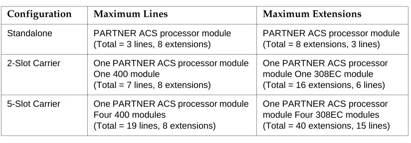
Table 1-3. Configurations for Maximum Lines or Maximum Extensions for Release 2.0
Configuration Maximum Lines Maximum Extensions
Standalone PARTNER ACS processor module (Total = 3 lines, 8 extensions)
PARTNER ACS processor module (Total = 8 extensions, 3 lines) 2-Slot Carrier One PARTNER ACS processor module
One 400 module
(Total = 7 lines, 8 extensions)
One PARTNER ACS processor module One 308EC module (Total = 16 extensions, 6 lines) 5-Slot Carrier One PARTNER ACS processor module
Four 400 modules
(Total = 19 lines, 8 extensions)
selects an available line from the pool. Since multiple lines are associated with the pool, the user does not know which line within the pool is being used to make the call.
System mode is determined by the configuration of the processor module. By default, the system is configured for Key mode. Changing to Hybrid mode requires modifying the processor module. Only Lucent Technologies Authorized Personnel can modify the processor module to accommodate Hybrid mode.
The mode for your system must be decided upon before installation; and in the continental U.S., the mode must be registered with the Federal Communications Commission (FCC) (see ‘‘FCC Registration’’ later in this section).
Key Mode
When the system operates in Key mode, individual outside lines are assigned to users’ extensions for making and receiving calls. At extensions with system phones, each individual line (Line 1, Line 2, Line 3, etc.) assigned to the extension is represented by its own line button. Users can press any of the available line buttons on their system phones to make outside calls. (Standard phone users must dial 9 at intercom dial tone to make an outside call since their phones do not have line buttons.)
Key mode enables users to easily join calls since each line button can be labeled using a unique line number. For example, if you are requested to join a call on Line 2, you simply press the line button labeled “Line 2.” Key mode also lets users monitor call activity using the lights next to the line button — everyone who has a specific line assigned to their extension can tell when an incoming call is ringing on that line, when a call on that line is on hold, and when that line is in use.
At installation, the system assigns outside lines to the buttons on all system phones from left to right, starting with the bottom row of buttons. On an extension basis, you can change which lines are assigned and which buttons are used to select the lines, if desired.
All extensions in a system configured for Key mode are referred to as key extensions.
Hybrid Mode
Hybrid mode offers users flexibility in accessing outside lines from their phones. As in Key mode, individual lines can be assigned to system extensions.
Additionally, multiple outside lines can be grouped together in pools.The system can have up to four pools, including a main pool and three auxiliary pools. Each pool is identified by a pool access code — 880, 881, 882, and 883 respectively.
buttons, put that call on hold, and make another call using the second main pool button. Or, the user can establish a conference call using lines in the main pool. The main pool and each auxiliary pool can be assigned to an extension, for a maximum of five pool buttons.
System phone users can press any of the available pool buttons on their phones or they can enter the pool access code at intercom dial tone to make an outside call. (Standard phone users must dial 9 or enter the pool access code at intercom dial tone to access a pool since their phones do not have pool buttons.) After the user presses a pool button or enters a pool access code, the system selects a free line from the pool for the user to make the call. A user can access a pool as long as there is at least one available line in the pool.
A major benefit of Hybrid mode is that it allows users who have system phones with fewer buttons to have access to multiple outside lines and various types of pools. You can make efficient use of outside lines by grouping those of a similar type or function together. For example, you can create an auxiliary pool of WATS or international lines and assign the pools to different groups of users.
Additionally, individual lines can be assigned to a manager’s extension so that he or she always has access to an outside line.
In Hybrid mode, extension 10 always operates like an extension in Key mode. This means that every outside line in the system is associated with a specific line button at extension 10.
All other extensions can be set up with access to only lines, only pools, or a combination of lines and pools:
■ Those extensions that have pool buttons, even if they also have individual line buttons, are called pooled extensions.
■ Those extensions that have only line buttons (including extension 10) are called key extensions. Key extensions cannot access pools.
If your system is configured for Hybrid mode, keep in mind:
■ A line can be assigned to only one pool.
■ Individual extensions can be restricted access to specific pools.
■ Individual lines can be assigned to an extension with pool buttons as long as the lines are not part of any pool.
FCC Registration
In the continental U.S., your system’s mode of operation must be registered with the FCC as either KF (Key Function) for Key or MF (Multifunction) for Hybrid. If the system is registered as KF, no outside lines can be pooled; if the system is registered as MF, lines can be pooled and individual lines also can be assigned directly to line buttons.
Telephones
System Telephones
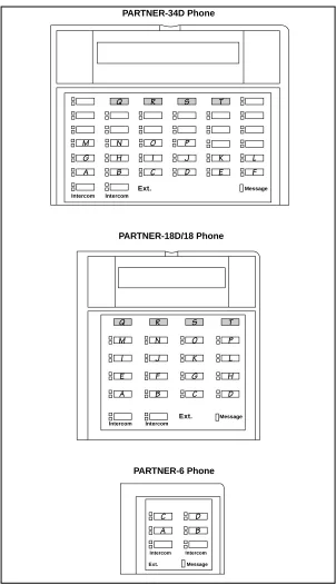
This guide refers to Lucent Technologies telephones specifically designed to work with the system as system phones. These include the PARTNER-34D,
PARTNER-18D, PARTNER-18, and PARTNER-6 telephones. You can also use MLS-34D, MLS-18D, MLS-12D, MLS-12, MLS-6, MLC-6, and the TransTalk© 9000-series wireless phones, including MDW 9000, MDW 9010, and MDW 9030P Pocketphone, although they are not discussed in this guide. For information about an MLS-model, MLC-model, or TransTalk 9000-series phone, refer to the
documentation that came with the phone.
System phones have several buttons in common: volume control buttons and the
f
,C
,A
,h
,!
andS
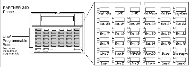
buttons. In addition, each phone has programmable buttons that can be used for outside lines, pools, extension numbers, outside phone numbers, or system features. Outside lines and pools, as well as some system features, require buttons with status lights. Programmable buttons without lines or pools assigned to them can be programmed with numbers or features, so you can use the feature or dial the number with one touch. The number in each PARTNER-model name indicates the number of programmable buttons with status lights and twoi
buttons.If the PARTNER-model phone has a display, indicated by a “D” in the model name, users receive messages and prompts when making calls and when programming. (More information about the display is provided in Chapter 5.) A system display phone is required for system programming.
Valid system extensions depend on which release of PARTNER ACS you have. Release 1.X extensions are 10 - 41. Release 2.x extensions are 10 - 49. Throughout this guide, all references to “system extensions” are within these release-dependent ranges.
Valid system lines also depend on which release of PARTNER ACS you are using. With System 1.X system line capacities are 01 to 15. With Release 2.0 or later, system line capacities are 01 to 19. Throughout this guide all references to “system lines” are within these release-dependent ranges.
Intercom Autodialers
PARTNER-model system phones support the PARTNER-CA48 Call Assistant Intercom Autodialer at extensions 10 and 11. The autodialer provides Auto Dial buttons for all of the extensions in your system. The status lights next to each button also indicate calling activity at that extension. Users can program the Auto Dial buttons for either intercom ringing, voice signaling, or manual signaling. (Note that each user can have only one Auto Dial button—either on the system phone or on the autodialer—for another extension in the system.) The Auto Dial buttons
Table 1-4. PARTNER-Model System Phones
PARTNER-34D PARTNER-18D PARTNER-18 PARTNER-6
Total Number of Programmable Buttons with Status Lights
32 16 16 4
Total Number of Programmable Buttons without Status Lights
4 4 0 0
Key Mode Line Button Capacity (Number of Programmable Buttons with Status Lights)
24 16 16 4
Hybrid Mode Pool Button Capacity1
1. The main pool uses two buttons.
5 5 5 4
Line Capacity 192
2. Since the system supports a maximum of 19 lines, when the system is configured for the maximum number of lines, you can use up to 19 buttons on these phones for outside lines.
163
3. The system supports a maximum of 19 lines; when the system is configured for the maximum number of lines, you can use up to 16 buttons on these phones for outside lines.
163 4
Intercom Buttons 2 2 2 2
Display ✔ ✔ — —
Standard Telephones
You can also use industry-standard single-line rotary or touch-tone telephones, including feature phones with built-in feature buttons and lights, with the system. This guide refers to such telephones as standard phones. Lucent
Technologies-certified standard phones are recommended.
The following Lucent Technologies phones can make use of the system’s message-waiting capability:
■ 2500 YMGL Single-Line Analog Telephone Set
■ 8101 Analog Telephone
■ 8101M Analog Telephone (This model is recommended.)
■ 8102 Analog Telephone
■ 8110 Analog Telephone
■ 7102 Plus Analog Voice Terminal
Check with your local Lucent Technologies Representative or local Authorized Dealer to find out whether other standard phones with message-waiting lights will work.
NOTE:
For message waiting capability, you must connect standard phones with LED-compatible message-waiting lights to a PARTNER ACS processor module, 308EC module, or to Release 3.1 (R3.1) or later 206 modules. This message-waiting capability does not work with standard phones with neon-type message-waiting lights.
Auxiliary Equipment
You can connect many types of telecommunications devices to your system without expensive adapters or additional phone lines—for example, answering machines, credit card scanners, and fax machines. Many industry-standard, single-line devices will work with the system regardless of the manufacturer.
Requirements
An industry-standard device must meet the following conditions:
■ It must be nonproprietary. That is, it cannot be made specifically for use on a particular telephone system. (For example, you cannot connect a Lucent Technologies MERLIN LEGEND® Communication System phone,
because it is specifically designed for use on a MERLIN LEGEND Communication System.)
■ Its Ringer Equivalence Number (REN1) cannot be greater than 2.0. (The REN is shown on a label on the device, usually on the bottom.)
■ You can connect a standard two-line device to the system, but for best results it should be installed and used as if it were a single-line device.
Connecting Standard Devices
2
Overview
After the system hardware is installed, you can customize the system and individual telephones. This chapter explains how to use programming to accomplish that.
There are two types of programming:
■ System Programming allows you to customize the system to meet the
needs of your business. When the system is first installed, it uses factory settings that reflect the most commonly used options. You can change system settings as needed.
You can perform System Programming from either extension 10 or 11. Because an extension cannot be in programming mode and handle calls at the same time, consider using extension 11 for programming. Doing so gives you the ability to program without disrupting call handling by the receptionist at extension 10.
■ Telephone Programming allows telephones to be customized to meet
individual users’ needs. Individual telephones can be programmed either from extension 10 or 11 (Centralized Telephone Programming), or from a user’s extension using a system phone (Extension Programming).
A system display phone is required for System and Centralized Telephone Programming. If you have any 34-button phones in the system, you must use a 34-button display phone to program since an 18-button phone cannot be used to program a 34-button phone. Also, if your system has both PARTNER-model and MLS-model phones, it is recommended that you use a PARTNER-model display phone at the programming extension.
The system permits programming from a remote location using a Remote Administration Unit—see ‘‘Remote Programming’’ on page 2-24.
and step-by-step instructions, refer to that name in Chapter 5. (A Programming Quick Reference is provided at the end of this book.)
Hardware Considerations
Programming procedures use line and extension numbers. The line number represents the line jack on a 206, 308EC, or 400 module or an ACS processor module to which the outside line is connected. Similarly, the extension number represents the extension jack on a 206 or 308EC module or an ACS processor module to which the system phone or standard device is connected.
For each 206 module, the system assigns two lines and six extensions; for the 308EC or ACS processor module, the system assigns three lines and eight extensions; for each 400 module, the system assigns four lines. The system numbers lines and extensions consecutively from left to right in a 2-Slot carrier, beginning with the ACS processor module in the leftmost slot; in a 5-Slot carrier, the numbering also begins with the ACS processor module (in the center slot), and then moves to the leftmost module and continues consecutively from left to right.
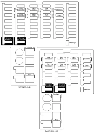
Figure 2-1 shows the numbering scheme for a PARTNER ACS standalone
Figure 2-1. PARTNER ACS Standalone, 2-Slot, and 5-Slot Systems Configured for Maximum Lines (3, 7, or 19)
Figure 2-2. Standalone, 2-Slot, and 5-Slot Systems Configured for Maximum Extensions (8, 16, or 40)
1 2 3 10 11 12 13 14 15 16 17 1 2 3 10 11 12 13 14 15 16 17 1 2 3 10 11 12 13 14 15 16 17 L I N E S L I N E S 12 13 16 17 Line Jacks Line Jacks L I N E S L I N E S 14 15 18 19 Line Jacks Extension Jacks 5-Slot Carrier ACS Processor
Module 400 Modules
Initial System Setup
After the control unit is installed, you set up the system using a combination of system and telephone programming procedures. In this guide, System
Programming procedures are identified by a code (# and three digits); Telephone Programming procedures are identified by the feature name only.
Use the System Planner as a guide when programming. The following sections provide an overview of the procedures you use for initial system setup. Chapter 5 explains how to use the specific procedures. Other programming procedures are optional, but are strongly recommended to make the most of your investment. (See ‘‘System Programming Options’’ on page 2-11 and ‘‘Telephone
Programming Options’’ on page 2-24 for details.)
Setting the System Clock
After supplying power to the control unit, use the following procedures:
■ System Date (#101) to set the month and day.
■ System Day (#102) to set the day of the week.
■ System Time (#103) to set the hour and minutes.
Assigning Lines
Key Extensions
Use the procedures described in this section to assign individual lines to pooled extensions or assign lines to key extensions. (In Key mode, all extensions are Key extensions; in Hybrid mode, extension 10 and any extensions set to Key using Line Access Mode (#313) are key extensions.)
For initial setup only, use Number of Lines (#104) to specify the number of lines that will be assigned to all system extensions. Then use the following procedures as needed:
■ Dial Mode (#201) to identify any rotary lines (the default for all lines is “touch-tone”).
■ Line Assignment (#301) to assign lines to specific extensions (if the line was not assigned using the Number of Lines procedure), to remove lines from some extensions, or to change the button used to pick up a line at a specific extension.
■ Line Ringing (Centralized Telephone Programming) to specify when a line will start ringing at each extension that has the line. For additional
information about line ringing options, see ‘‘Programming a
Receptionist’s Extension’’ on page 2-26.
■ Automatic Line Selection (Centralized Telephone Programming) to specify the order in which the system selects an available line (intercom or outside), when a user at the extension lifts the handset or presses
S
to make a call without first selecting a specific line button.For extensions with standard phones, set Automatic Line Selection to intercom first. This enables standard phones to access system features, including intercom calling. When users lift the handsets on standard phones, they hear intercom dial tone. To access an outside line, they must dial
9
.Pooled Extensions
Use the procedures described in this section if your system is configured for Hybrid mode to change the assignment of lines in pools and to assign auxiliary pools to or remove the main pool from pooled extensions. If a pooled extension also has an individual line, refer to ‘‘Key Extensions’’ to assign that individual line.
For initial setup only, use Number of Lines (#104) to specify the number of lines that will be assigned to the main pool. Then use the following procedures as needed:
■ Dial Mode (#201) to identify any rotary lines (the default for all lines is “touch-tone”).
■ Pool Line Assignment (#207) to remove lines from the main pool and assign lines to auxiliary pools.
■ Line Access Mode (#313) to change a specific extension’s operation from Pooled to Key. Refer to ‘‘Key Extensions’’ to assign lines to those extensions.
■ Pool Extension Assignment (#314) to remove the main pool, assign auxiliary pools, or change the location of the button used to select an auxiliary pool at specific extensions. (The location of the two main pool buttons cannot be changed.)
■ Pool Access Restriction (#315) to prevent an extension from receiving and/or making outside calls on all lines in specific pools.
■ Line Ringing (Centralized Telephone Programming) to specify when a line or pool will start ringing at each extension that has the line or pool. By default, lines are set to Immediate Ring and pools are set to No Ring. For additional information on line ringing options, see ‘‘Programming a
■ Automatic Line Selection (Centralized Telephone Programming) to specify the order in which the system selects an available line or pool, when a user at the extension lifts the handset or presses
S
to make a call.For extensions with standard phones, set Automatic Line Selection to intercom first. This enables standard phones to access equipment features, including intercom calling. When users lift the handsets on standard phones, they hear intercom dial tone. To access a pool, they can dial the pool access code 880, 881, 882, or 883 or dial 9 to access the first available line or pool in the sequence.
Customizing Extensions
In addition to line or pool assignments, the following procedures can be used to customize an extension:
■ Line Coverage Extension (#208) to identify an extension as the “owner” of a specific outside line. A user at the extension can activate Call
Coverage or VMS Cover for the specified line. Use Call Coverage Rings (#116) to specify the number of times a call should ring at the owner’s
extension before it is sent to the covering extension or VMS Cover Rings
(#117) to specify the number of times a call should ring at the owner’s
extension before it is sent to the owner’s voice mailbox.
■ Caller ID Call Log Line Association (#318) to select the lines to associate with extensions for logging unanswered calls. Users can view the Caller ID information for unanswered calls on the phone’s display panel and autodial the numbers of the unanswered calls.
■ Display Language (#303) to specify the language (English, French, or Spanish) for messages that appear on a system display phone.
■ Automatic Extension Privacy (#304) t o prevent other extensions with the same line from joining a call at the extension. This feature is also useful for extensions connected to a modem, fax, or any device whose function can be disrupted by someone trying to join it.
■ Forced Account Code Entry (#307) to prevent the extension from making an outside call until a required account code is entered. You can also use
Forced Account Code List (#409) to create a list of valid account codes;
this ensures that only authorized users with valid account codes can make outside calls.
■ Call Waiting (#316) to identify standard phone extensions that can receive the system (not the local telephone company) call-waiting tone for a second incoming call when active on a call.
■ Disallowed List Assignments (#405) to assign one or more Disallowed Phone Number Lists to the extension. Use Disallowed Phone Number
Lists (#404) to create the lists of outside numbers that extensions cannot dial.
■ Allowed List Assignments (#408) to assign one or more Allowed Phone Number Lists to the extension. Use Allowed Phone Number Lists (#407) to create the lists of outside numbers that otherwise-restricted extensions can dial.
■ Pickup Group Extensions (#501), Calling Group Extensions (#502),
Night Service Group Extensions (#504), and Hunt Group Extensions (#505) to place the extension in any of these groups. See ‘‘Setting Up Groups of Extensions’’ on page 2-15 for more information.
■ Fax Machine Extensions (#601), Doorphone Extension (#604 and
#605), Doorphone Alert Extensions (#606), AA Extensions (#607), External Hotline (#311), or Hotline (#603) to identify the extension as one
of these equipment types.
‘‘Setting Up Auxiliary Equipment’’ on page 2-15 provides an overview of
the procedures you use for setting up devices such as voice messaging systems and call reporting devices. Also, Chapter 4 provides detailed information and example applications for auxiliary equipment.
Copy Settings
The recommended way to set up your system is to program one extension for each type of phone in the system, then use Copy Settings (#399) to program other phones of the same type. For example, you can program one
PARTNER-18D phone and then copy its settings to any other extensions that have PARTNER-18D or PARTNER-18 phones. See "Copy Settings (#399)" on page 5-90 for a list of the programmed settings that are copied.
Changing Settings after Installation
As your business grows or changes, you will probably need to change the way your system was originally programmed. This section provides some examples and lists the procedures you would use to change settings after installation. For specific details on a procedure, refer to the procedure name in Chapter 5.
If you are upgrading to PARTNER A CS Release 1.1 or 2.0 or later from an earlier release using the PC Card upgrade, all of your system programming settings will be converted to work with the new release. However, you may want to consider some additional programming for the features that are new in Release 2.0 or later. The new programmable features are:
■ Automatic System Answer Button (#111)
■ Automatic System Answer Lines (#204)
■ Automatic System Answer Mode (#121)
■ Automatic System Answer Record/Playback (I891)
■ Call Coverage (F20, XX, XX)
■ Call Coverage Rings (#116)
■ Caller ID Call Log Line Association (#318)
■ Caller ID Log Answered Calls (317)
■ Direct Extension Dial Button (#113)
■ Direct Extension Dial Delay (#112)
■ Direct Extension Dial Lines (#205)
■ Direct Extension Dial Record/Playback (I892)
■ Pool Access Restriction (#315)
■ Pool Extension Assignment (#314)
■ Pool Line Assignment (#207)
■ SMDR Talk Time (#611)
■ PARTNER Voice Messaging PC Card (PARTNER ACS Release 1.1 or later).
For more information about setting these features, see Chapter 5, "Feature Reference".
For more information on using the PC Card Software Upgrade, see ‘‘Upgrading
from PARTNER ACS Release 1.0 to Release 1.1 or Release 2.0 or Later’’ on page 2-24 in this section.
For more information on using the PARTNER Voice Messaging PC card, see PARTNER Voice Messaging PC Card Installation, Programming and Use.
Changing the System Clock
You may need to change the system clock for daylight saving time, after a prolonged power failure, or after a system reset. Use System Date (#101),
System Day (#102), and System Time (#103) to set the current date, day, and
Adding New Lines
Key Extensions
Use this section to add individual lines to pooled extensions or to add new lines to key extensions (all extensions in Key mode; in Hybrid mode, extension 10 and any extensions set to Key using Line Access Mode (#301) are key extensions.)
If you add an outside line to your system, you may need to adjust some line settings. In particular, use Dial Mode (#201) if the new line is a rotary line, Line
Assignment (#301) to assign the line to specific extensions, Line Ringing
(Centralized Telephone Programming) to specify when the line will start ringing at each extension that has the line, and Line Access Restriction (#302) to limit an extension’s access to the line. Additionally, the system automatically assigns the new line as the last line in the Automatic Line Selection sequence. If you want to change the order, use Automatic Line Selection (Centralized Telephone Programming).
IMPORTANT:
Do not use Number of Lines (#104) if you add lines to the system after initial setup, because it changes Line Assignment (#301), Line Access Restriction
(#302), Automatic Line Selection, and Line Ringing for existing lines back to
factory settings. To add a new line without affecting other settings, use Line
Assignment (#301).
Pooled Extensions
Use this section to add new lines to existing pools if your system is configured for Hybrid mode. To assign a new line to a pooled extension as an individual line, follow the procedures in “Key Extensions.”
If you add an outside line to your system for use in an existing pool, use Dial
Mode (#201) if the new line is a rotary line and Pool Line Assignment (#207) t o
add the line to an existing pool.
IMPORTANT:
Do not use Number of Lines (#104) if you add lines to the system after initial setup, because it changes Pool Line Assignment (#207), Pool Extension
Assignment (#314), Pool Access Restriction (#315), Automatic Line Selection, and Line Ringing for existing pools back to factory settings.
Additionally, it changes Line Assignment (#301), Line Access Restriction
(#302), Automatic Line Selection, and Line Ringing for individual lines back to
factory settings. To change pool assignments without affecting other settings, use
Adding New Pools
Use this section if your system is configured for Hybrid mode to create new pools. If you add outside lines to your system for use in a new pool, use Dial Mode
(#201) if the new lines are rotary lines, Pool Line Assignment (#207) to assign
lines to the new pool, Pool Extension Assignment (#314) to assign the new pool to specific extensions, Line Ringing (Centralized Telephone Programming) to specify when the new pool will start ringing at each extension that has the pool, and Pool Access Restriction (#315) to limit an extension’s access to all the lines in the new pool. Also use Automatic Line Selection (Centralized Telephone Programming) to add the new pool to the extension’s Automatic Line Selection sequence.
Adding New Extensions
If you add an extension to your system, you can probably use Copy Settings
(#399) to copy the settings of an existing extension. If you wish to further adjust a
new extension’s settings, see ‘‘Customizing Extensions’’ on page 2-6.
Swapping Extensions
If a user changes location, but wants to keep the same extension number, you can make the change easily by changing the connection at the control unit.
For example, if the users at extensions 29 and 32 switch offices, you can
disconnect the modular plugs from those extension jacks in the control unit. Then reconnect the plug from 32 into extension jack 29 and the plug from 29 into extension jack 32. Now the users can take their respective phones to their new locations, keep the same extension numbers, and retain the phones’ programmed settings.
Changing Settings to Support
PBX or Centrex Services
This section applies only if you use PBX or Centrex services with your system. If it does not apply, go to the next section, “System Programming Options.”
■ PBX services are provided by a private telephone switch.
Some of the issues you should consider when setting up your system to work effectively behind a PBX or Centrex system are discussed below. Chapter 5 explains how to use the programming procedures discussed here.
Recall Setting
To set up your equipment to work properly with a PBX or Centrex system, first set
Recall Timer Duration (#107) to match the setting used by your PBX or Centrex
system (usually 800 msec, or “32”). This setting affects the length of a Recall signal sent by the control unit to access PBX or Centrex services.
Dialing Restrictions
Outgoing Call Restriction (#401) is an equipment restriction intended to limit an
extension’s dialing to “inside calls only” (using the
i
buttons on system phones) or to “inside and local calls only” (allowing calls within the PBX or Centrex system and local calls outside the PBX or Centrex system). However, if users in your system use a dial-out code (9 on most PBX or Centrex systems) before dialing numbers outside the PBX or Centrex system, the equipment will not be able to prevent toll calls for extensions restricted to “inside and local calls only” (unless you use Disallowed Phone Number Lists (#404) to prevent dialing to specific classes of numbers).If your PBX or Centrex system includes dialing restrictions, use those instead of the equipment restrictions. If you have PBX or Centrex dialing restrictions on a line and also program equipment restrictions, both the PBX or Centrex system and equipment restrictions apply. However, equipment dialing permissions will not override PBX or Centrex system restrictions.
Speed Dial and Auto Dial Numbers
When you program numbers outside the PBX or Centrex system as Speed Dial and Auto Dial numbers, include the PBX or Centrex system dial-out code (9 on most systems), followed by one or more pauses, in the stored number.
System Programming Options
Speed Dialing
You can program up to 100 frequently dialed phone numbers—such as numbers for suppliers, repair services, customers—so that all users in the system can dial them by pressing four buttons:
f
(or#
on a standard phone) plus a three-digit code. These are called System Speed Dial Numbers.Dialing Restrictions and Permissions
The system has several procedures for restricting telephone use, and several for overriding those restrictions. You can use any combination of these procedures to design a system that meets your needs.
When a user makes a call, the system checks the number dialed against all of the dialing that apply to the extension making the call. When the number dialed passes a restriction, the system goes to the next restriction, if necessary. If Star
Code Dial Delay (#410) is active, star codes are also checked against the
restrictions. (Star codes, typically dialed before an outgoing call, provide special services from the local telephone company Central Office (CO); for example,
*
6
7
enables a dialer to block the sending of Caller ID information to the called party.) When a user dials a star code, the system checks it against the dialing restrictions to determine whether the code is allowed. If the code is allowed, the system resets its checking procedure and checks the remaining digits that the user dialed to make sure the call is permitted. When a number violates arestriction, the call is stopped and the user hears a reorder tone (fast busy signal).
IMPORTANT:
While procedures that restrict dialing are very effective, absolute protection against misuse cannot be guaranteed. System phones provide more protection than standard phones. Therefore, it is strongly recommended that you install system phones where restricting phone use is important.
Locking an Extension
The system offers a Station Lock feature that lets users enter a four-digit code on their telephone dialpad to lock their extensions. This helps prevent other users from making outside calls at those extensions.
Restricting Access to Outside Lines or Pools
NOTE:
If Forced Account Code Entry (#307) is programmed for an extension, that extension is required to enter an account code before dialing an outside number—even those on the Emergency Phone Number List (#406) — on all of the lines or pools assigned to that extension. If the Forced Account
Code List (#409) contains entries, the system checks the account code
against the list. If the account code is on the list, line or pool access is allowed; if not, line or pool access is denied.
Controlling Calls on Outside Lines
When an extension is allowed access to an outside line or pool, you can use the following procedures to control calling:
■ Outgoing Call Restriction (#401) defines the type of calls (inside only, local only, or inside, local, and long-distance) that users can make from all lines or pools available at an extension. Outgoing Call Restriction Button
(#114) allows the receptionist at extension 10 to quickly change an
extension’s current Outgoing Call Restriction setting.
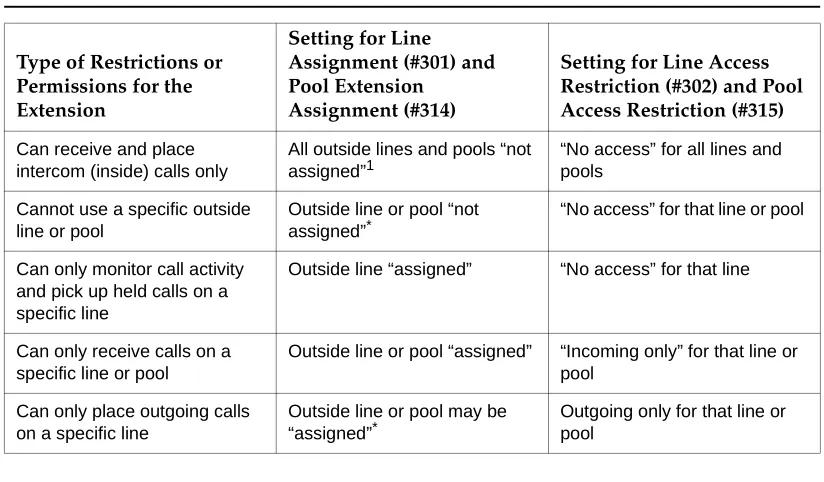
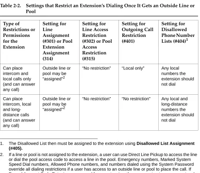
Table 2-1. Settings that Restric