Western University Western University
Scholarship@Western
Scholarship@Western
Electronic Thesis and Dissertation Repository
8-9-2013 12:00 AM
Electrospinning of Core-shell Collagen Nanofibers
Electrospinning of Core-shell Collagen Nanofibers
Ying Li
The University of Western Ontario
Supervisor Dr. Wankei Wan
The University of Western Ontario
Graduate Program in Chemical and Biochemical Engineering
A thesis submitted in partial fulfillment of the requirements for the degree in Master of Engineering Science
© Ying Li 2013
Follow this and additional works at: https://ir.lib.uwo.ca/etd
Part of the Other Biomedical Engineering and Bioengineering Commons, Polymer and Organic Materials Commons, Polymer Science Commons, and the Process Control and Systems Commons
Recommended Citation Recommended Citation
Li, Ying, "Electrospinning of Core-shell Collagen Nanofibers" (2013). Electronic Thesis and Dissertation Repository. 1499.
https://ir.lib.uwo.ca/etd/1499
Electrospinning of Core-shell Collagen
Nanofibers
(Thesis format: Monograph)
by
Ying (Betty) Li
Graduate Program in Chemical and
Biochemical Engineering
A thesis submitted in partial fulfillment of the requirements for
the degree of Master in Engineering Science
The School of Graduate and Postdoctoral Studies
The University of Western Ontario
Abstract
In tissue engineering, the scaffold plays a critical role in guiding and supporting cells
to function and grow optimally. The electrospun nanofibrous scaffold can serve as a
near ideal substrate for tissue engineering because it has high surface area and the
three-dimensional interconnected porous network can enhance cell attachment and
proliferation. Core-shell nanofibrous scaffolds produced with coaxial electrospinning
allow bioactive molecule encapsulation to improve cell adhesion, mediate and
promote the proper signaling among the cells for their functioning and growth. In the
current study, core-shell collagen nanofibers were fabricated via coaxial
electrospinning with horizontal and vertical configurations. Core-shell nanofibers
with optimum morphology and structure were stablized with Genipin, a natural
crosslinking reagent extracted from the fruits of Gardenia jasminodies. The produced
crosslinked core-shell collagen fibrous scaffolds have been proven to be cell
compatible with improved structure stability and uniformity.
Acknowledgments
As with any considerable body of work, there are always a significant number of
people to thank for helping make it possible. I would like to start by thanking my
supervisor, Dr. Wankei Wan, for taking considerable amount of time and energy to
teach me, both with respect to my work and in life. He has always pushed me to work
hard and challenged my mind with insightful questions.
I would like to thank all the members in the group as well as everyone else I have had
the pleasure to work with. I consider each of you friends and I always love the talks
we had, the food we shared, and the challenges we worked through together.
Much of this work would not have been possible without the help and support of Dr.
John deBruyn, Dr. Jian Liu, and Helium Mak. I would like to thank Dr. deBruyn for
providing me the high speed camera and viscometer; Dr. Jian Liu and Helium Mak for
giving me supports and suggestions throughout my work.
I would like to thank Karen Nygard, Dr. Richard Gardiner and everyone at the Biotron
for providing me with the technical support.
My gratitude also extends to my advisory committee: Dr. Andrew Hrymak and Dr.
Andy Sun. I would like to thank them for giving me helpful advice and suggestions.
Finally, I would like to thank my families, who have supported me unconditionally
throughout all these years.
Table of Contents
Abstract ... ii
Acknowledgments... iii
Table of Contents ... iv
List of Tables ... viii
List of Figures ... ix
List of Abbreviations ... xiv
1 Introduction ... 1
2 Background and literature review ... 4
2.1 Electrospun Nanofibers History ... 4
2.2 Fundamentals of electrostatically induced jets ... 4
2.3 Electrostatically induced jets... 5
2.4 Formation of Bending instability ... 6
2.5 Parameters effects on nanofiber diameter and morphology ... 9
2.5.1 Jet cross-sectional radius... 10
2.5.2 Needle collector separation distance on fiber diameter and morphology ... 11
2.5.3 Viscosity ... 11
2.5.4 Concentration ... 12
2.5.5 Conductivity ... 12
2.5.6 Solvent types and vapor pressure ... 13
2.5.7 Electric potential ... 13
2.5.8 Other parameters ... 14
2.6 Effects of Electrospinning Setup ... 15
2.7 Coaxial electrospinning ... 16
2.9 Processing parameters for coaxial electrospinning ... 20
2.9.1 Applied voltage ... 20
2.9.2 Flow rate ... 20
2.9.3 Solution viscosities ... 21
2.9.4 Solution concentration ... 21
2.9.5 Solution conductivity ... 22
2.9.6 Solution miscibility ... 22
2.9.7 Solvent vapor pressure ... 23
2.10 Fiber morphology and alignment ... 24
2.11 Properties and Applications of Core-shell Nanofibers... 24
2.12 Collagen as a biomedical material ... 25
2.13 Crosslinking of electrospun collagen nanofibers ... 26
2.13.1 Cabodiimides ... 27
2.13.2 Glutaraldehyde ... 29
2.13.3 Genipin ... 33
3 Materials and Method ... 40
3.1 Materials ... 40
3.2 Isolation and purification of Type I Collagen from Rat Tails ... 40
3.3 Core and shell solutions for electrospinning ... 41
3.3.1 Collagen Shell Solution ... 41
3.3.2 Protein Core Solution ... 41
3.4 Coaxial Electrospinning ... 41
3.5 High speed imaging ... 43
3.6 Genipin crosslinking ... 43
3.7 Resin Embedding and Ultramicrotoming ... 44
3.8.1 Scanning electron microscopy (SEM) ... 44
3.8.2 Transmission electron microscopy (TEM) ... 44
3.8.3 Laser scanning confocal microscopy (LSCM) ... 45
3.9 Image processing (Image J) ... 45
3.10 Cell seeding experiments ... 45
3.10.1 Cell attachment ... 46
3.10.2 Cell staining ... 46
4 Results ... 48
4.1 Optimizing electrospinning process ... 48
4.1.1 Effect of voltage on fiber diameter ... 51
4.1.2Effect of other experimental parameters ... 53
4.1.3Effect of solution parameters ... 54
4.1.4 Effect of environmental parameters ... 56
4.2 Protein encapsulation of the core-shell collagen nanofibers ... 57
4.3 Core-shell structure of the collagen nanofibers ... 58
4.4 Optimizing the vertical coaxial electrospinning process ... 62
4.4.1 Effect of voltage and tip-to-collector distance on fiber morphology .. 65
4.4.2 Effect of environmental parameters ... 68
4.5 The core-shell structure of the vertical coaxial electrospun nanofibers ... 68
4.6 Genipin crosslinking on core-shell collagen nanofibers preparation ... 73
4.7 Change in auto-fluorescent before and after crosslinking (LSCM) ... 75
4.8 Cell attachment ... 76
5 Discussion ... 78
6 Summary and Conclusion ... 83
References ... 87
Appendix A Isolation of Type I Collagen from Rat Tails ... 99
Appendix B Low Viscosity Embedding Media (Spurr's Kit) ... 100
Appendix C TEM on Fiber Breakage ... 103
Appendix D TEM images on fiber cross-section ... 104
List of Tables
Table 1: Materials for electrospinning and fiber characterization of core-shell
collagen nanofibers ... 40
Table 2: Horizontal coaxial electrospinning parameters for core-shell collagen nanofibers ... 49
Table 3: Average fiber size vs. applied voltage for horizontal coaxial electrospinning ... 52
Table 4: Vertical coaxial electrospinning parameters for core-shell collagen
nanofibers ... 63
Table 5: Average fiber size for vertical coaxial electrospinning ... 67
List of Figures
Figure 1: Glycerol jets profile at 0.5mL/min. Left to right: 3.67kV/cm, 4.33kV, 5.0kV/cm (adapted from [18]) ... 7
Figure 2: Illustration of the jet bending at the end of the straight segment. (Adapted from [19]) ... 7
Figure 3: Horizontal electrospinning setup ... 15
Figure 4: a: shaft type vertical electrospinning. b: converse type vertical
electrospinning ... 15
Figure 5: Coaxial electrospinning ... 18
Figure 6: Compound jet formation a: a compound droplet formed at the tip of the spinneret, b: shell solution elongates and stretches due to charge-charge
repulsion, c: stream ejected from the Taylor cone ... 18
Figure 7: Voltage dependence of the core-shell fiber formation. A: voltage below optimal range (subcritical voltage), B: optimal voltage (critical voltage), C:
voltage above optimal range (super critical voltage) ... 20
Figure 8: Crosslinking of collagen with EDC and NHS. ... 28
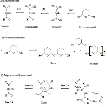
Figure 9: Possible structure of glutaraldehyde (GA) in aqueous solutions ... 30
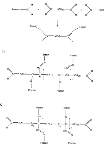
Figure 10: a: Schiff base formation obtained by crosslinking of lysine residues from two protein molecules by monomeric glutaraldehyde. b: Suggested end
product obtained from the reaction between the polymeric glutaraldehyde
with lysine residues from the crosslinked proteins under alkaline conditions.
c: Suggested end product obtained from the reaction between the polymeric
glutaraldehyde with lysine residues from the crosslinked proteins under
acidic conditions ... 31
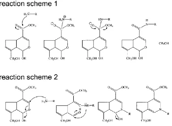
Figure 12: The two reaction mechanisms between genipin and a primary amine group,
proposed by Butler et al. [96] ... 34
Figure 13: Schematic illustration of the intramolecular crosslinking structure of genipin crosslinks [97] ... 35
Figure 14: Formation of intermolecular chains with genipin ... 36
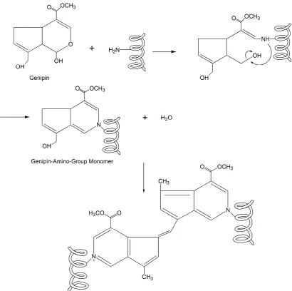
Figure 15: Reaction mechanism of genipin crosslinked collagen proposed by Zhu et al. [100] ... 37
Figure 16: Genipin crosslinking mechanism proposed by Muzzareli [101] ... 38
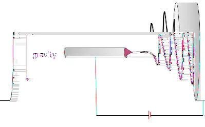
Figure 17: Humidity controlled chamber for electrospinning ... 42
Figure 18: Horizontal coaxial electrospinning configuration ... 42
Figure 19: Vertical coaxial electrospinning setup configuration ... 43
Figure 20: Redlake MotionScope M high speed camera captured stable Taylor cone formed at the tip of the needle (Horizontal configuration). ... 50
Figure 21: Distorted Taylor cone due to gravitational force and extended coaxial electrospinning ... 51
Figure 22: SEM image of horizontal coaxial electrospun collagen nanofibers at 22kV, 7cm ... 51
Figure 23: Histogram of horizontal coaxial electrospun collagen nanofiber size distribution obtained at six applied voltages with 7cm tip-to-collector distance. ... 52
Figure 24: Average fiber size at applied voltage between 19kV to 25kV with a tip-to-collector distance of 7cm ... 53
Figure 25: Coaxial electrospun collage nanofibers with increased flow rate (OFR:0.3mL/hr, IFR: 0.1mL/hr) and yielded beads-on-string morphology fiber ... 54
Figure 27: Distorted Taylor cone during electrospinning with increased temperature (a: 22°C, b: 29°C, c: 34°C) ... 56
Figure 28: At 34°C, fiber ejected out brokenly from the Taylor cone. a: suspended droplet with no applied electric field, b,c,d: with applied electric field,
droplet distorted due to both electrostatic force and gravitational force, e,f:
fiber shooting out from tip of the distorted Taylor cone, g: after solution
being carried out by the fiber, droplet size reduced and electrospinning
process stopped. Same process would continue with increasing droplet size
due to continuous solution pumping (the series images were screen captured
from a high speed video, the spinning process from first to last image took
about 0.2s) ... 57
Figure 29: Confocal images of as-prepared electrospun core-shell BSA-PEG/collagen nanofibers: a) auto-fluorescence of collagen; b) fluorescent-labelled
BSA-Alexa Fluoro 594 in the core material; c) overlaid image of collagen
and BSA-Alexa Fluoro 594 fluorescence ... 58
Figure 30: TEM on core-shell collagen nanofibers. The dark core and light shell in some of the fibers indicates the difference in electron transmission ability
with the core shell material ... 59
Figure 31: TEM on core-shell collagen nanofibers. There are fibers with dark core light shell and fibers with dark shell light core ... 59
Figure 32: Non-uniform distribution of core-shell material along the nanofiber. The fiber showed dark core light shell at the left side of the image while evolving
into dark shell lighter core as moving to the right side ... 60
Figure 33: Three possible types of resultant fiber structure:(a)core-shell structure, (b)separate core fibers and shell fibers, and (c) composite fibers from
Figure 34: Non-uniform distribution of cross-section of core-shell material from horizontal coaxial electrospinning, both the edge and centre of the fiber
display dark regions ... 62
Figure 35: Electrostatic force and gravitational force act together to pull out extra solution from the increased-size droplet to form Taylor cone (Captured with
AOS-QPRI camera) a: solution accumulated at the tip of the needle, b:
Taylor cone distorted due to applied electric field, c,d: stream ejecting from
the apex of the Taylor cone, e: Taylor cone size reduced to stable Taylor
cone ... 64
Figure 36: Stable Taylor cone with continuous fiber drawing, no solution dripping, no change in Taylor cone size and shape a: focus on the fibers (Captured
with Olympus I-speed 3 camera) b: focus on the Taylor cone ... 65
Figure 37: SEM image on vertical coaxial electrospinning at 7cm, not much fiber can be collected with solution mostly dripped onto the substrate. ... 65
Figure 38: Coaxial electrospraying with droplets formation ... 66
Figure 39: Coaxial electrospinning produced combination of fiber and droplets ... 66
Figure 40: Stable coaxial electrospinning result smooth nanofibers with no droplet or beads ... 67
Figure 41: Histogram of fiber size distribution collected with optimum range using vertical coaxial electrospinning (fitted with normal function) ... 67
Figure 42: For vertical coaxial electrospinning, nanofibers whipped upward with fumehood air and stuck to the needle. (Image was captured with AOS Q-PRI
camera) ... 68
Figure 43: Dark core structure close to the surface of the fiber, thick fiber breakage allows observation of the core-shell structure ... 69
Figure 45: TEM images on the cross-section of the vertical coaxial electrospinning nanofibers ... 71
Figure 46: Microtoming directionality determines the resultant cross-section shape. a: round fiber cross-section. b: ellipse shape cross-section ... 71
Figure 47: Cross-section of the genipin-crosslinked core-shell nanofibers with BSA encapsulation ... 72
Figure 48: Cross-section of the uranyl acetate stained nanofibers ... 72
Figure 49: SEM images on Left: The as spun electrospun core-shell BSA-PEG/collagen nanofibers . Right: Electrospun core-shell
BSA-PEG/collagen nanofibers immersed in water for 5 seconds. ... 73
Figure 50: Left: As-spun core-shell core-shell BSA-PEG/collagen nanofibers on aluminum foil. Right: Crosslinked core-shell core-shell BSA-PEG/collagen
nanofibers turned blue ... 74
Figure 51: Left: Crosslinked collagen core-shell nanofibers. Right: Crosslinked collagen core-shell nanofibers immersed in water for 7 days ... 74
Figure 52: Confocal images of crosslinked electrospun core-shell BSA-PEG/collagen nanofibers: genipin crosslinked nanofibers fluorescence overwhelmed other
fluorescence signals ... 75
Figure 53: Fluorescence images of primary human fibroblasts cultured on crosslinked BSA-PEG/collagen core-shell nanofibers (3D) a: cell nucleus; b: filamentous
actin; c:crosslinked-nanofibers; d: overlaid image (scale bar = 20μm) ... 76
Figure 54: Fluorescence images of primary human fibroblasts cultured on crosslinked BSA-PEG/collagen core-shell nanofibers (3D). Blue: cell nucleus, green:
actin filament, red: genipin-crosslinked core-shell collagen nanofibers. Side
List of Abbreviations
BSA bovine serum albumin
DHT dehydrothermal
DMF dimethyformamide
ECM extracellular matrix
EDC 1-ehtyl-3-(3-dimethyl aminopropyl) carbodiimide
FBS fetal bovine serum
GA glutaraldehyde
HA hyaluronan
HFIP hexafluoroisopropanol
IFR inner solution flow rate
LSCM laser scanning confocal microscopy
NHS n-hydroxysuccinimide
OFR outer solution flow rate
PBS phosphate buffered saline
PDT poly(dodecylthiophene)
PEG poly(ethylene glycol)
PEO poly(ethylene oxide)
PVA poly(vinyl alcohol)
SEM scanning electron microscopy
TEM transmission electron microscopy
1 Introduction
Disease, injury and trauma can cause damage and degeneration of tissues and organs
in the human body. Treatments are needed to facilitate their repair, replacement or
regeneration. These treatments typically involve the use of autografts or allografts [1].
However, tissue availability from the patient may be limited and in the case of
allografts, immune rejection and donor availability place limits to their use [2].
Alternatively, an approach using tissue engineering to regenerate the damaged tissues
by implanting biological substitutes that restore, sustain or improve tissue function
was applied. In this technique, cells from the patient's body are isolated, expanded,
and cultured on a three-dimensional porous supporting structure called scaffold for
implantation [3]. It is assumed that the cells will adhere to the scaffold, proliferate and
produce the natural tissue replacement [4].
In tissue engineering, the scaffold plays a critical role as it provides mechanical
support for the cells to function and grow optimally. Several design criteria have been
proposed for an ideal scaffold [5]:
1) the scaffold surface should allow cell adhesion, growth and differentiation;
2) the material used to construct the scaffold should be biocompatible, degradable and
its degradation by-products should not provoke inflammation or cytotoxicity
3) the scaffold structure should be highly porous to allow cell growth and
extracellular matrix (ECM) regeneration, nutrients diffusion and waste-product
removal from the cells
4) the porous structure of the scaffold should permit uniform cell distribution
throughout the scaffold to form a homogeneous tissue
6) the scaffold should be mechanically strong to stimulate cell growth.
and the cost effectiveness. In this technique, charged polymer solution was flowing
out of a capillary at a high drawing ratio. With strong electrostatic field, the obtained
nanofibers form a nonwoven scaffold. A typical electrospinning setup operates by
applying an electrostatic potential between the spinneret and a collector, with fluid
slowly pumping through the spinneret. Both the spinneret and collector are
electrically conducting and separated by a distance of 5 ~30 cm in between. While the
jet stream travels from the conducting spinneret to the collector, the collector can be
covered with a removable substrate for easier harvesting of the deposited scaffold.
Electrospinning has been performed with either horizontal or vertical configuration to
produce solid nanofibers with different fiber diameters and morphologies.
Coaxial electrospinning has emerged as a branch of electrospinning and the resulting
nanofibers possess a core-shell structure [6]. In contrast with the solid electrospun
fibers, core-shell nanofibers provide a feasible route for controlled release of
embedded bioactives that are required for stimulating cell growth, proliferation and
migration. Although electrospinning was performed in both horizontal and vertical
configurations, all the reported coaxial electrospinning studies were performed with
vertical configuration only. The effects of different configurations on coaxial
electrospinning process and resultant fibers quality have not been studied.
Collagen, a major component of the extracellular matrix (ECM) and the most
common structural protein in the human body, is one of the most promising
candidates for tissue regeneration scaffold applications [7]. Electrospinning has been
utilized to create nonwoven nanofibrous solid collagen scaffolds. However,
electrospinning does not reproduce the structure of native collagen fiber. These fibers
possess poor mechanical properties and are unstable in aqueous environment [8, 9].
Crosslinking is required to stabilize the electrospun collagen nanofibers. Studies have
been done to stabilize electrospun collagen nanofibers, and showed the
have been made on fabrication and stabilization of core-shell collagen nanofibers with
bioactive molecule encapsulation. The objectives of the current research are to
(1) Utilize coaxial electrospinning to prepare core-shell collagen nanofibers to
encapsulate a model protein (i.e. bovine serum albumin (BSA))
(2) Stabilize the core-shell collagen nanofiber with genipin crosslinking reagent, and
(3) Demonstrate the stability and biocompatibility of the core-shell collagen
2 Background and literature review
Electrospinning is one way to directly engineer nanofibers with diameter of tens to
hundreds of nm. Nanostructures which are made via electrospinning have nonwoven
structure with interconnected pores and large surface-to-volume ratio. These features
enable such nanofibrous scaffolds to have many biomedical and industrial
applications. The processing flexibility in tailoring scaffold properties, such as fiber
diameters, scaffold size, porosity,and texture, offers the possibility to design
electrospun scaffolds that can meet the demands of numerous practical applications.
The stability of the nonwoven structures, which depends on the chemical composition
and processing procedure, can be further improved by post processing.
2.1 Electrospun Nanofibers History
The process of using electrostatic forces to form synthetic fibers has been known for
over 100 years. This process, known as electrospinning, was first observed by
Rayleigh in 1897 who utilized high voltage source to inject charge of a certain
polarity into a polymer solution, which is then accelerated toward a collector of
opposite polarity. In 1914, Zeleny studied the process in detail on electrospraying
where the solution came out as droplets instead of fibers [10] and the process was
patented by Formhals [11] in 1934. The theoretical and experimental work by Taylor
and others on electrically driven jets has laid the groundwork for electrospinning [12].
Taylor produced useful experimental evidence, and calculated the conical shape of the
protrusion where a jet leaves the surface of a liquid [13].
2.2 Fundamentals of electrostatically induced jets
When an external electrostatic field is applied to a conducting fluid, a suspended
conical droplet, whereby the surface tension of the droplet is in equilibrium with the
overcome the surface tension of the liquid, the liquid droplet at the tip of the spinneret
then becomes unstable, and the liquid jet is ejected from the surface of the droplet. As
the jet travels and whips in air, the solvent evaporates and is collected on a grounded
target.
The charged liquid jet, consisting of sufficiently long-chain molecules and without
breakup due to the Rayleigh instability, can elongate into a single fiber of
considerable length with an extremely small diameter. The small fiber diameter is also
responsible for the high specific surface area to volume ratio which is important for
many biomedical and industrial applications. The high degree of molecular alignment
is caused by the very large effective spin draw ratio and results in unique mechanical
properties of the nanofibers.
2.3 Electrostatically induced jets
The surface of the fluid droplet held by its own surface tension at the spinneret tip
gets electrostatically charged. Excess charges in the solution tend to move toward the
part of this shape that protrudes the most with highest curvature. The subsequent
charge accumulation causes the shape to distort and extend more to eventually form a
conical shape. The interactions of the electric charges in the polymeric fluid with the
external electric field cause the droplet to form a conical shape called Taylor cone [12,
14]. Accumulation of the charge at the tip of the cone increases the charge density in
that region even further. The electrode shape and spinneret diameter are designed to
yield a high electric field strength with an appropriate field gradient at the tip of the
cone, so a fluid jet stream can be ejected out by overcoming the surface tension.
Subsequently, the surface tension causes the droplet shape to relax again, but the
liquid jet continues to be ejected in a steady fashion, namely, steady-state
[15]. Electrostatic repulsion of the charges in the jet tends to increase its surface area,
thus reduce fiber diameter for fibrous structure. The effect of electrostatic repulsion is
similar to that of stretching by mechanical drawing in conventional fiber spinning. If
the liquid is a solution and the solvent gradually evaporates, the concentration and the
viscosity of the liquid would change and the electrostatic repulsion effect would be
enhanced.
In any liquid, the surface tension tends to reduce the total surface of the jet, but not by
keeping the fiber diameter large. Rather, what usually occurs is an instability that
causes the jet to break up into droplets, each with a surface-minimizing spherical
shape. This effect is known as Rayleigh instability [16]. If the viscosity of the fluid is
sufficiently high and the fluid contains long-chain molecules, the fluid jet stream
diameter will continuously shrink to very small value until the essentially dried
filament is eventually deposited onto the collector, and at the same time, the solvent is
evaporated along the jet stream pathway. This is the desired situation for
electrospinning.
If Rayleigh instability occurs for long-chain molecules that cannot be easily broken up
into discrete droplets, a “pearls-on-a-string” morphology, also known as “beading”,
can be formed. The occurrence of beading depends on the processing variables [17],
especially the viscosity and the surface tension.
The strong repulsion due to high surface charges may, in principle, also be utilized to
initiate a bifurcation process in which the jet stream is spatially separated into
subfibers, known as splaying or branching.
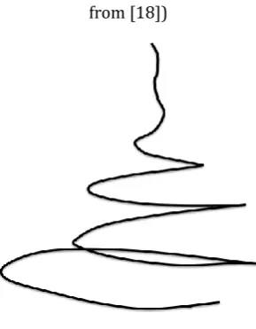
2.4 Formation of Bending instability
During the electrospinning of an aqueous solution of high molecular weight polymer,
surface of a pendent drop of solution the electrically charged jet traveled for a few
centimeters in a straight line. At the end of this straight segment, a diaphanous shape,
also conical, with its vertex at the end of the straight segment was seen when proper
illumination was provided [19]. This cone is the envelope, in space, of the
complicated set of paths taken by a jet during the observation time. Baumgarten and
Warner [20, 18] using appropriate illumination to observe and track the travelling path
of the jet indicated that the jet was continuously bending for as far as it could be
followed after it entered the envelope cone (Fig 2).
Figure 1: Glycerol jets profile at 0.5mL/min. Left to right: 3.67kV/cm, 4.33kV, 5.0kV/cm (adapted
from [18])
Figure 2: Illustration of the jet bending at the end of the straight segment. (Adapted from [19])
After traveling linearly for a certain fraction of its path, solvent continuously
stress caused by the external electric field acting on the charge carried by the jet
stabilized the straight jet for some distance. Then a lateral perturbation grew in
response to the repulsive forces between adjacent elements of charge carried by the jet.
The motion of segments of the jet grew rapidly into an electrically driven bending
instability [21]. This instability appears to be splaying in the form of repeated
bifurcations, the initial single jet stream lead into multiple jet streams. However,
subsequent experiment gathered with high speed cameras and theoretical models
suggested that the apparent splaying was an optical illusion in the form of a very fast
whipping motion of the jet [14]. Reneker and coworkers [19, 21] explained the
observed whipping motion by a bending instability. The bending instability often
causes the whipping jet to assume a spiraling loop conformation (Fig 2).
Shin et al. [13] developed a theory for electrified fluid jets to describe the
electrospinning process using operating diagrams of electric field versus flow rate to
define regions of stable fiber formation. By assuming the fluid is Newtonian and
incompressible, electrohydrodynamic equations were developed for conservation of
mass, conservation of charge and differential momentum balance. The steady state jet
profiles can then be calculated numerically. Based on their previous work [22], their
systematic experimental and theoretical analysis suggests that three different types of
instability can be predicted: two axisymmetric modes and one non-axissymmetric
mode. Whereas the first axisymmetric mode is associated with the classical Rayleigh
instability, which is dominated by surface tension and resulted in the nearly straight
region in the jet path. The other two modes are electrically driven, and it is the
competition between the two conducting modes that is of importance at the
high-applied fields. Their results showed good agreement between experiments and
theory, but they also indicated that a third operating parameter, the electric current, is
also crucial but not an independent parameter in the experimental process. The charge
Reneker et al. [21] used a theoretical model of the electrospinning process to calculate
the three-dimensional paths of continuous jets, both in the nearly straight region
where the instability grew slowly and in the region where the bending dominated the
path of the jet. The mathematical model provides a reasonable representation of the
experimental data, particularly of the jet paths determined from high speed
videographic observations. The theory accounts for the nonlinear effects that are
characteristic of finite perturbations, as well as for the rheological behavior of
viscoelastic liquids.
Although mathematical model and experimental data did show good agreement, in
many ways, mathematical models are oversimplification because they ignore
couplings among parameters for real materials.
2.5 Parameters effects on nanofiber diameter and morphology
The fiber diameter and morphology can be controlled by various parameters, such as
applied electric field strength which is tailored by applied voltage between spinneret
and collector; distance between the spinneret and the collecting substrate; temperature;
feeding flow rate; humidity; air velocity; and properties of the solution, including
polymer type, molecular weight, surface tension, conductivity, and viscosity.
Moreover, solution properties such as surface tension, conductivity, and viscosity,
depend not only on temperature but also concentration. Other variables which are not
stated are dependent on one or more other variables such as solution concentration,
solvent quality, additives and temperature-dependent behavior of these parameters.
At the same time, jet formation also depends on the electrode design and electric field
strength at the tip of the spinneret, whereas fiber formation from the jet stream also
depends on the fluid flow rate and the solution evaporation rate [23]. In some cases, to
concentration and surface tension [6].
The properties of the electrospun scaffold can also be modified by post-spun process
such as annealing, stretching or crosslinking, which can improve their mechanical
properties or/and degradation behavior.
Thompson et al. [23] studied the effects of experimental parameters on nanofiber
diameter based on electrospinning model. The model indicates which parameters have
the greatest influence on the fiber diameters. Among the 13 material and operating
parameters studied in the paper, researchers evaluated the parameters on a relative
basis to determine a strong-moderate-minor rating for the influence on the nanofiber
diameter [24]. The result showed that volumetric charge density, distance from nozzle
to collector, initial jet radius, relaxation time, and viscosity are the five parameters
having the most significant effect on the jet radius. Initial polymer concentration,
solution density, electric potential, perturbation frequency, and solvent vapor pressure
have moderate effects on the fiber diameters. While parameters such as relative
humidity, surface tension, and vapor diffusivity have minor effects on the resulting jet
radius [23]. Although the study hasn't considered the effect of temperature,
temperature does factor indirectly into the calculations through changes in solution
density, vapor diffusivity, viscosity, relaxation time, etc. In addition, other potential
factors such as solution pH, charge polarity and pressure were not included in the
model for studying [23].
2.5.1 Jet cross-sectional radius
By normalizing the results from other research literature to the model in the paper,
Thompson et al. [23] predicted that the jet cross-sectional radius starting at the nozzle
is directly related to needle size based on the single paper on electrospun
jet diameter at the tip of the Taylor cone is significantly affected by the applied
voltage, jet cross-sectional radius cannot be treated as a fully independent parameter
when the applied voltage changes.
2.5.2 Needle collector separation distance on fiber diameter and morphology
The electrospinning literature reports different separation distances between the
needle and collector separation distance in the experimental setups. Although not all
research articles report the effects of separation distance on final cross-sectional fiber
diameter, in several experiments, it was reported that a decrease in fiber diameter with
increase in collector distance when smooth fibers were produced [25]. On the contrary,
with beaded fibers present, the beads tend to grow larger as distance increased
probably due to the capillary instability, which have more time to develop [26].
Although Still et al. pointed that beaded morphologies only occur when the distance
between the needle and collector is too short [27].
2.5.3 Viscosity
Viscosity plays an important role in governing electrospinning, it is directly controlled
by the molecular weight and solution concentration [28, 29]. Most viscosity values
were measured at zero-shear values. The experimental data showed a strong
dependence on viscosity for fiber morphology [30, 31]. An increase in viscosity,
beyond minimum necessary, increases visco-elastic force which opposes columbic
force and leads to an increase in fiber diameter [6]. Increasing zero-shear viscosity
will increase the resulting fiber radius, however, if the solution viscosity is above a
critical value, the shear between the solution and the spinneret wall would prevent the
2.5.4 Concentration
The basic requirement for fiber formation is sufficient inter-chain entanglements, so
polymer concentration, which affects both viscosity and surface tension of the
solution, plays a crucial role in electrospinning process. If the solution concentration
is too low, the as spun fiber will break up into droplets due to the effects of surface
tension, whereas a concentrated solution enables high viscosity making jet
initialization extremely difficult. In most experiment, the effect of concentration was
not studied; the initial polymer concentration was maintained constant for other
variables. A report on Nylon-6 showed increased fiber diameters with increasing
initial polymer concentration [26]. It was also reported that as the polymer
concentration increase, the as spun structure changed from highly beaded fiber to
uniform morphology and eventually to a ribbon-like structure [33]. Similar studies on
electrospun collagen nanofibers also indicated that only concentrations above a
threshold (5wt%) will allow fiber formation [9].
2.5.5 Conductivity
Fluids with high conductivity have high surface charge density. Under a given electric
field, this results in an increase in the elongation force on jet, which is caused by the
self-repulsion of the excess charges on the surface [23]. This inhibits the Rayleigh
instability, enhances whipping and leads to finer fibers [6]. Since most synthetic
polymers do not carry charge, it is preferred to increase solution conductivity by
adding extra salts or polyelectrolytes in the solution [34]. Solution with higher
conductivity undergoes a greater tensile stretch caused by self-repulsion of the excess
charges distributing on the surface. It also prevents axisymmetric instability and
creates thinner fibers to some extent [21]. Thus, with increasing solution conductivity,
2.5.6 Solvent types and vapor pressure
Several studies reported on the effect of various solvents and their effect on the
electrospinning process [35, 36]. Discussions in these works indicated that low vapor
pressure solvents tend to inhibit solution flow which prevents a fully developed
Taylor cone to be maintained due to low charge density or high viscosity. High vapor
pressure solvent may bring about irregular multiple jets emerging from the droplet
[32]. Megelski et al. [37] examined the polystyrene fibers fabricated from solutions
containing various ratios of dimethyformamide (DMF) and tetrahydrofuran (THF).
100% THF as solvent gives rise to many deep pores embedded in fibers, whereas
smooth fibers with complete loss of microtexture yielded from 100% DMF solvent.
Between these two extremes, pore gradually became enlarged and shallowed as the
solvent volatility decreased with decreased THF percentage [37]. As most of the
information on vapor pressure is related to morphological changes due to conductivity,
viscosity or surface tension, and considering various solvents, it is difficult to make
true comparison due to the variation of other solvent properties and lack of data on the
vapor pressure effect [23].
2.5.7 Electric potential
Katti et al. [5] reported an initial decrease in diameter of poly(lactide-co-glycolide)
fibers with an increase in electric potential from 8-10 kV, but no significant
correlation with subsequent increases. No such results have been reported by other
researchers and one research showed no significant change in fiber diameter for
solution with different initial polymer concentration at different applied voltage [38].
Still et al. [27] studied the effect of applied voltage on fiber morphology and
2.5.8 Other parameters
No literature research has been reported on vapor diffusivity while the effect of
humidity on fibers was dealt with the development of porous fibers [39]. Moreover,
the effects of relative humidity are strongly coupled to other parameters and operating
conditions, so the coupled effects cannot be directly identified [23]. For surface
tension, it was shown that the effect of the surface tension is negligibly small when
electrospinning solutions retain their viscoelasticity, indeed, Thompson et al. indicated
that the viscoelastic forces completely dominate the surface tension [23]. With low
molecular weight polymers or when polymer concentrations are significantly reduced,
the viscoelastic forces dramatically diminish and surface tension then plays a strong
role in the morphology of the resulting fibers. In these cases, beaded fibers tend to
form for higher surface tension solvents, low viscosity and low conductivity/charge
density systems. Polymer feed rate has influence on fiber morphology as well as
scaffold porosity [32]. It maintained the Taylor cone by keeping a mass balance
between the feed solution and ejected stream. It has been reported that fiber diameter
and pore sizes increase as flow rate increases until formation of ribbon-like structure
[33] and beaded morphologies occur if the flow rate is too high [27].
Air velocity also has an effect on the morphology of the fibers. According to the
model adapted by Thompson et al. these effects are not linear and do not necessarily
mean that the quality of the product is maintained but give a general idea about the
trends [23].
The electrospinning process is complex and it is difficult (or in some cases,
impossible) to experimentally vary one parameter while others are kept constant. The
reports on varying one parameter at a time give insight into the electrospinning
process and suggest that to better control the process one must control the parameters
relatively narrow set of manufacturing conditions that provide optimum results.
Moreover, most of parameters effect investigations were done on solid fibers. With
coaxial electrospinning, which is the current spinning system, no work has been
reported to systematically investigate the effect of these parameters.
2.6 Effects of Electrospinning Setup
The arrangement for electrospinning could be horizontal or vertical according to the
geometrical arrangements of the spinning needle and collector, where vertical type
includes shaft type and converse type (Fig 3, 4).
Figure 3: Horizontal electrospinning setup
Figure 4: a: shaft type vertical electrospinning. b: converse type vertical electrospinning
Using different electrospinning system configurations, the obtained fiber properties
could be quite different. The vertical setup allows solution flow to be inline or against
gravity. Yang et al. [40] studied the differences of fibers diameters and fibers mats
morphology between the three electrospinning systems. The results showed that in the
shaft type system, the electrospinning fibers were the thinnest as the gravitational
force strengthen the effect of electric field to maximize fiber extension. While this
setup results in the broadest fiber diameter distribution. In the converse type system,
the average fiber diameter was the largest and the fiber diameter distribution was the
narrowest. The horizontal type system resulted in average fiber diameter and size
distribution between shaft and converse types [40].
In another study, Rodoplu and Mutlu [41] indicated that the effect of gravitational
force on electrospinning process is negligible with respect to the electric field forces.
However, they also found that gravity has an effect on the shape of the polymer
droplet and the Taylor cone. This results in a difference in electrospinning parameters
used in horizontal and vertical systems.
These studies were all based on electrospinning setup used for producing solid
nanofibers, the effect of electrospinning configuration on coaxial electrospinning has
not been reported.
2.7 Coaxial electrospinning
Coaxial electrospinning has emerged as a branch of electrospinning, the resulting
nanofibers possess a core-shell structure. Similar to electrospinning, coaxial
electrospinning employs electric forces acting on polymer solutions in DC electric
fields and resulting in significant stretching of polymer jets due to a direct pulling and
growth of the electrically driven bending perturbations [42, 43]. Comparing to
electrospraying, where the jets should be rapidly atomized into tiny core-shell droplets,
with no viscoelasticity or jet bending involved; coaxial electrospinning produces jet
A novel idea in developing scaffolds is to use core-shell structure with two different
polymers that degrade at different rates. Such spinning was first demonstrated by
King et al. [9] using bicomponent carpet fiber melt-spinning technology to spin
resorbable materials. The idea of coaxial electrospraying for encapsulation of liquid
droplets was also introduced by Loscertales et al. [45] and the same principle has been
successfully applied to electrospinning of composite and hollow fibers by several
groups [46, 47, 48].
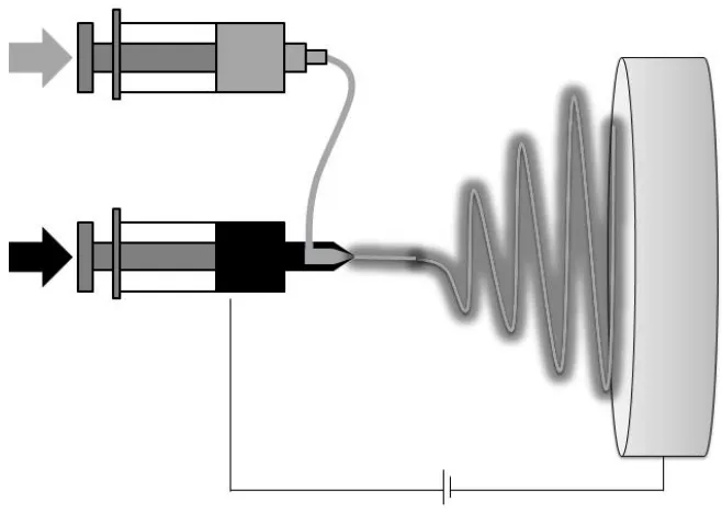
2.8 Coaxial electrospinning setup and process
Coaxial electrospinning is an important method used to form bicomponent continuous
nanofibers through spinning solutions of two dissimilar polymers within a concentric
needle. This results in an end product that comprises the two polymers in a distinct
shell and core form [32]. Coaxial electrospinning setup adopted by most researchers is
quite similar to that used for electrospinning of solid fibers. A smaller (inner) capillary
that fits concentrically inside the bigger (outer) capillary makes the coaxial spinneret
(Fig 5). The two compartments containing different polymer solutions or a polymer
solution in the shell and a non-polymeric Newtonian liquid or even a powder in the
Figure 5: Coaxial electrospinning
Two polymers solutions are held in separate syringes and fed independently through
the concentric needle. At the exit of the coaxial needle appears a core-shell droplet,
when electric field is applied, the charge accumulation occurs predominantly on the
surface of the shell liquid coming out of the outer coaxial needle (Fig 6a) [49].
Figure 6: Compound jet formation a: a compound droplet formed at the tip of the spinneret, b: shell solution elongates and stretches due to charge-charge repulsion, c: stream ejected from the Taylor cone
The pendant droplet of the shell solution elongates and stretches due to the
charge-charge repulsion to form a conical shape (Fig 6b) and once the charge
stream is ejected from the cone (Fig 6c). The stress generated in the shell solution
causes shearing of the core solution via "viscous dragging" and "contact friction" [50].
This causes the core liquid to deform into the conical shape with the shell solution and
a compound coaxial jet develops at the tip of the cone. Liquid in the compound cone,
being subjected to a sufficiently strong electric field, forms a compound jet, which
undergoes the electrically driven bending instability [46, 51, 52]. Strong jet stretching
resulting from the bending instability is accompanied by enormous jet thinning and
fast solvent evaporation. As long as the process becomes stable, the as-spun fibers
undergo bending instability for stretch and the resultant core-shell jet solidifies and
depositing on the counter-electrode. This technique has found broad applications,
especially for polymers that are difficult to be spun alone [6]. Coaxial electrospinning
improves the properties of a nonwoven fibrous mat, such as creating controlled
degradation rate, controlling mechanical properties [53], or serving as a scaffold for
tissue engineering where a less-biocompatible polymer is surrounded by a
biocompatible material so that the overall structural integrity of the scaffold can be
maintained with the structural support of the inner component [54].
As the shell and core solutions are in contact and undergo the same bending instability
and whipping motion, the degree of dissimilarity between the two solutions, in terms
of composition, physical and rheological properties, plays an important role in the
formation of the composite fibers [6].
Moghe et al. claimed electrospinnable shell solution was a fundamental requirement
to ensure continuous fiber formation [6]. A stable Taylor cone created by shell
solution would spontaneously cooperate with core solution by interfacial viscous drag
to form a coaxial jet. However, several studies used liquids such as mineral or olive
oil as core material and obtained hollow fibers [50, 55]. Indeed, electrospinable shell
2.9 Processing parameters for coaxial electrospinning
2.9.1 Applied voltage
As most studies only used one voltage value for specific compound cone stabilization,
no systematic investigation of this parameter has been done. For a given pair of
polymer systems and flow rates, it was found that there exists a narrow range of
applied voltage in which a stable compound Taylor cone can be formed (Fig 7b).
Below this optimal range, both or any one liquid cannot be driven out and results in
discontinuous dripping (Fig 7a) [6]. Due to the increased size of the cone, mixing of
the two solutions tended to occur [56]. Voltage above the critical range caused the
strength of the electric field to exceed that required for the material and the processing
conditions used. Instead of the coaxial jet, separate jets formed from the shell and core
solutions (Fig 7c).
Figure 7: Voltage dependence of the core-shell fiber formation. A: voltage below optimal range (subcritical voltage), B: optimal voltage (critical voltage), C: voltage above optimal range (super critical voltage)
2.9.2 Flow rate
Flow rate of the two solutions are crucial to the structure of the core-shell fiber,
especially the thickness of the two layers [33]. Several groups found the core and
the other one [57, 58]. By keeping the shell flow rate constant while change the core
solution flow rate, several groups found the volume expansion of the overall droplet.
Eventually, with increasing in core flow rate while keeping the shell flow rate
constant, the shell solution may fail to appropriately encapsulate the inner liquid, and
cause a disrupted process. Typically, the core flow rate is lower than the shell flow
rate, however, insufficient delivery of core material may lead to discontinuous
segments in the fibers [59].
2.9.3 Solution viscosities
The electrospinnable shell solution drove the inner liquid, dominating the fiber
formation process. The viscosity of the shell solution is required to be such that the
viscous stress imparted on the core is sufficient to overcome the interfacial tension
between the two solutions and allows the formation of a compound Taylor cone [59].
Viscosity of the shell solution is critical and the shell polymer solution should be
electrospinnable by itself to lead the core-shell structure formation. It appears that the
requirements for the spinnability of the core solution by itself are not as critical as
they are for the shell material [6].
2.9.4 Solution concentration
The polymer concentration determines the spinnability of a solution, the solution must
have a high enough concentration for chain entanglements to occur. An increasing
solution concentration would increase fiber diameter for conventional single fluid
electrospinning, similar effect has been observed in coaxial electrospinning. Zhang et
al. [60] reported increased core diameters and overall fiber diameters by increasing
core solution concentration while keeping the shell concentration constant. It was
found that the ratio of outer layer thickness to that of inner one decreased at the same
He et al. on the other hand, inversed Zhang’s process by using shell solutions with
different concentrations to create nanofibrous drug release systems. They found that
as the shell solution concentration increases, the fiber diameters increase as well [61].
2.9.5 Solution conductivity
The difference in conductivity between the shell and core solutions has a great impact
on charge accumulation, which determines the origin of the jet. Yu et al. [62] found
discontinuity in the core-shell structure occurs if the conductivity of the core solution
is higher and is being pulled at a higher rate. On the other hand, higher shell
conductivity imposes higher shear stress on the inner material, which induces a
thinner core structure [33]. Even non-conductive or less conductive liquids can be
incorporated into a higher conducting shell to form core-shell structure [6].
2.9.6 Solution miscibility
The interaction between the core and shell solutions governs the resultant fiber
structure, the interfacial tension between the shell and core solution should be as low
as possible for the generation of the stabilized compound Taylor cone [59]. However,
some researchers reported that if the core and shell solutions are miscible, mutual
diffusion starts as soon as the two fluids encounter at the tip. It might last at the order
of 1 second before forming a compound cone [6]. Li [50] and Kurban [63] revealed
that fiber morphologies strongly depend on degree of miscibility of the two solutions.
Fibers electrospun from immiscible solutions had a distinctive core-shell structure,
whereas fibers embedded with dense through-pores were created in semi-miscible
systems. Miscible systems failed to form fibers although the shell solution was
electrospinnable on its own. The fast diffusion may perturb Taylor cone formation or
make shell material permeate into core solution, disrupting the electrospinning
Sun et al. [46] insisted that the characteristic time of diffusion spreading of a
boundary between two miscible solutions was much greater than that of whipping
instability, thus no mixing took place. Distinguishable core-shell structure of
poly(dodecylthiophene) (PDT, core) and poly(ethylene oxide) (PEO, shell) in
chloroform was derived from his system demonstrated that extensive mixing did not
take place.
Diverse results reported for the use of miscible core/shell polymer solutions were
based on observations on limited work. This indicates that further research is needed
for a clearer understanding of the condition that would restrict mixing when miscible
core-shell polymer solutions are used.
2.9.7 Solvent vapor pressure
The type of solvent used for core and shell solutions can have effects on the resulting
morphology of the core shell structure. Li et al. [48] reported that when high vapor
pressure solvents (e.g. chloroform, acetone etc.) were used in the core, a thin layer of
the core material formed at the interface of the shell and the core due to rapid
evaporation of core solvent. This layer traps the interior solvent that diffuses out more
slowly due to the newly created barrier. When the core solvent fully leaves the
structure, it creates a vacuum. This vacuum in the core causes the core structure
collapse and form ribbon-like fibers under atmospheric pressure [48]. Moghe et al.
also found a collapsed core structure when chloroform was used as a solvent for the
core polymer [56]. In their experiment, the shell solution used was poly(vinyl alcohol)
(PVA) in water and the core was poly(ethylene oxide) (PEO) dissolved in chloroform.
Since the stabilized compound Taylor cone and the initial jet are required for the
coaxial electrospinning, high vapor pressure solvents should not be used as they may
2.10 Fiber morphology and alignment
If the collector in the electrospinning process is a plate, the deposited nanofibers
typically assume a completely isotropic orientation. However, for many applications,
it is desired to control the alignment of the fibers. For example, aligned nanofibers can
enhance cell attachment and proliferation [65]. To introduce uniaxial alignment into
the nanofiber deposited, the fibers should be collected on a rotating drum with the
rotation speed matching the extremely high speed of the whipping motion caused by
the bending instability. However, the achievable degrees of alignment obtained by this
method are limited [6].
Several groups have studied different collector configuration to control the orientation
of electrospun fibers. As Xia and coworkers [66, 67] showed, using a paired electrode
with a gap in between, uniaxial alignment of the deposited nanofibers can be obtained.
The fibers span across the gap from hundreds of micrometers to several centimeters.
Using geometric configurations consisting of multiple pairs of electrodes and
sequentially activates pairs of electrodes, one can guide the nanofiber alignment and
generate more complicated aligned nanofiber fabrics [67, 68].
2.11 Properties and Applications of Core-shell Nanofibers
Coaxial electrospinning rapidly became popular and is used by many research groups
for different purposes. In particular, coaxial electrospinning allows encapsulation in
the core or wrapping as a shell for non-spinnable polymers, or non-polymeric
materials like powders, nanoparticle suspensions, catalysts, and proteins [52, 69].
One of the possible motivations for applying coaxial electrospinning is to modify
wetting properties of nanofiber surface [59, 70]. Some groups work with applying
coaxial electrospinning for encapsulation of drugs or biologically active objects in the
biologically active agents in the core can be protected from harsh solvents with the
spinnable polymer solution in the shell.
2.12 Collagen as a biomedical material
Natural biopolymers are often of interest as they simulate a biomimetic environment
for tissue regeneration. Chitosan, hyaluronan (HA), heparin, collagen are examples of
natural polymers that have been extensively used in biomedical applications.
Collagen is one of the most promising candidates for tissue engineering applications.
It is the major component of the ECM and the most common structural protein in the
human body. It serves for the maintenance of the structural integrity of tissues and
organs and is involved in the interaction with specific receptors that define cellular
adhesion, differentiation, growth and survival [74]. Most of collagen molecules
self-assemble into insoluble, triple-helical structures that are packed together into the
staggered patterns called fibril and act as the major stress-bearing component of
connective tissues and of the fibrous matrices of skin and blood vessels. Over the last
20 years, increased interest has emerged in the use of collagen and
collagen-containing tissues in medical devices. Purified collagen obtained from
animal tissue can be processed to generate collagen containing products that find
applications not only in the medical field, but also in manufacturing of cosmetics,
water treatment and nanofluidics [75]. The individual polypeptide chains of collagen
contain 20 different amino acids and the precise composition varies among different
tissues. There are over twenty genetically different types collagen molecules located
in many diverse tissues within the human body given by the variation in specific
amino acid sequence. Collagen type I and III are the most abundant types and they
form the long-recognized characteristic fiber bundles seen in tissues [7]. Type I
collagen is found within skin, ligaments, tendons and bone while type II is found in
chains with carboxyl groups, interconnected by covalent and hydrogen bonds. The
triple helical structure protects the collagen fiber from being broken down by
proteases and is important for cell adhesion and the assembly of the ECM.
2.13 Crosslinking of electrospun collagen nanofibers
The electrospinning process allows the production of fibers with diameters down to
the tens of nanometer range. Using this method, 3-D scaffolds made from collagen
fibers with interconnected pores can be generated. The porous structure enables cells
and blood vessels to infiltrate into the construct in vivo [3, 7]. It is desirable to have a
3D structure of organized collagen fibers to better mimic native tissue environments
to guide the tissue regeneration process [76]. However, electrospinning produces only
collagen fibers that are unstable in aqueous environments. Post processing techniques
such as crosslinking treatment is therefore necessary to stabilize these fibers to be
useful for our purposes.
Crosslinking is essential to stabilize the electrospun nanofibers by targeting
intramolecular covalent bonds. It is accomplished by the reaction of functional groups
on the surface of collagen fiber that can bridge and link to construct an
interpenetrating and water-resistant network. Furthermore, crosslinking can tailor the
rate of biodegradation, providing collagen networks the specific rate to degrade into
bioresorbable components as cells produce their own ECM [77]. A number of
cross-linking methods have been shown to successfully improve the stability and
mechanical properties of collagen-based scaffolds [78, 79, 80]. These methods can be
categorized into chemical, physical or biophysical crosslinking. Although physical
methods can avoid introduction of potentially toxic residuals, the degree of
crosslinking achievable is limited. Therefore, chemical crosslinking treatment is the
preferred choice [81]. Performance of the resulting scaffolds were studied by
mechanical properties, their biocompatibility and cell compatibility of the nanofibers
[82, 83]. The common chemical crosslinking treatment of protein in general and
collagen in particular involves the use of a carbodiimide, glutaraldehyde and genipin.
2.13.1 Cabodiimides
Carbodiimide treatments are used to form crosslinks between different functional
groups within the collagen molecules, without itself being incorporated. They can be
used to establish an isopeptide bond between the carboxyl and amino groups from
amino acid residues; the only byproduct of this reaction is water-soluble urea which
can be easily removed [84].
Two different carbodiimides have been used to crosslink collagen: cyanamide or
1-ethyl-3-(3-dimethyl aminopropyl) carbodiimide (EDC) [80], while EDC is more
commonly studied.
EDC contributes no components to the final crosslinked product, and the two
crosslinking residues must be in direct contact in situ, hence the crosslinks formed are
referred to as “zero length” crosslinks. EDC has been used to enhance the biostability
of collagen scaffolds in the presences of N-Hydroxysuccinimide (NHS), which helps
to prevent the formation of side products and to increase the reaction rate. For
electrospun fibers, solvents which can preserve fiber morphologies are needed.
Possible solvents for EDC crosslinking are proposed, including pure ethanol and
acetone/water mixture [85].
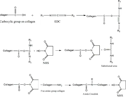
The chemical reactions of EDC/NHS crosslinking on collagen are outlined in Figure 8.
Crosslinking of the collagen material can be controlled by varying the EDC/NHS
concentration. By comparing EDC crosslinked dermal sheep collagen to GA
implantation studies showed the EDC/NHS crosslinked collagen samples had low
tendency to calcify with good biocompatibility [84]. The formed amide crosslinks
may be beneficial in terms of anticalcification due to the reduction in calcium binding
sites [85]. Lee et al. [86] crosslinked bovine pericardium with EDC/NHS, the
resulting materials had comparable in-vitro stability as GA crosslinked pericardium.
Figure 8: Crosslinking of collagen with EDC and NHS.
Haugh et al. [80] crosslinked collagen/glycosaminoglycan scaffolds using EDC,
glutaraldehyde (GA) and dehydrothermal (DHT) and investigated the effect of
crosslinking on compressive modulus and cellular attachment, proliferation and
migration of the scaffold. They demonstrated that a wide range of scaffold
compressive moduli that can be attained by varying the crosslinking treatment
parameters and claimed that EDC and GA produced the stiffest scaffold with
![Figure 15: Reaction mechanism of genipin crosslinked collagen proposed by Zhu et al. [100]](https://thumb-us.123doks.com/thumbv2/123dok_us/7791787.1291309/52.595.109.526.76.505/figure-reaction-mechanism-genipin-crosslinked-collagen-proposed-zhu.webp)
