P a g e | 945 Analysis Of Rectangular Resonant Microstrip Antenna Loaded With Metamaterial And A
Slot Loaded Rectangular Microstrip Antenna
SHIVARAM PORIKA1 ,A ARUNKUMAR2
1&2
assistant professor
Vaageswari College of engineering, karimnagar, Telangana.
1
[email protected],[email protected]
ABSTRACT: Authors analyze a slot loaded rectangular micro-strip patch antenna and a
sub-wavelength compact, resonant patch antenna loaded with metamaterial. The slot is taken as
capacitive reactance on the patch. It is found that the resonance frequency decreases with
increasing slot width for a given slot length the decrease in the resonance frequency in the lighter
side for longer slot length, where as it is in the min. side for the lower slot length, in case of
resonant patch antenna loaded with metamaterial the matching and radiation properties have
analyzed. It is shown how these configurations may exhibit in principle an arbitrarily low
resonant frequency for a fixed dimension, but they may necessarily radiate efficiently when their
size is electrically small.
Keywords: Microstrip antennas, Meta material
I. INTRODUCTION
Demand for compact radiators with
sufficiently high gain is rapidly increasing in
many application areas, as modern wireless
telecommunication systems and space
communications require compact antennas
with high gain, which become even more
relevant requirements when the radiating
elements have to be combined in large
antenna arrays for satellites, space vehicles,
airplanes, and so on. Microstrip antennas,
due to their inherent capabilities (mainly low
cost, low weight and low profile) are widely
used in those setups [1], [2]. Even though
such antennas are very thin compared to the
operating wavelength ( 0.05-0.01 λ ) in
their cross section, however, still their
transverse dimensions cannot be made
arbitrarily short, since a regular patch
antenna resonates at a given frequency when
its linear transverse dimension is of the
order of half wavelength. The interest in
overcoming this limitation represents one of
the main challenges for antenna designers.
P a g e | 946 an important role may be played by
metamaterials, which, due to their
interesting anomalous electromagnetic
features, have attracted a great deal of
attention in recent years for several
electromagnetic applications [3]. Interest is
focused in the presented paper on a typical
wave interaction of metamaterials with
anomalous electromagnetic constitutive
parameters, and in particular with negative
real part of their permittivity [ Є - negative
ENG)], of their permeability [µ -negative
(MNG)] or with both these quantities being
negative [double-negative (DNG)] in a
specific frequency range. The phase
compensation properties of DNG
metamaterials may allow synthesizing sub
wavelength cavity resonators [4],
waveguides [5] and scatterers [6] with
resonant properties essentially independent
on their effective physical size. In the
quasi-static limit, when the retardation effects are
negligible due to the small dimensions of
such components and only one of the two
constitutive parameters interact with the
field depending on its polarization, even
single negative (SNG) materials, i.e., ENG
or MNG, may be utilized to achieve similar
effects. Such sub-wavelength resonances
may be applied also to antenna
configurations. In the present paper, we
have comparatively analyzed the rectangular
antenna loaded with metamaterial and fed
with microstrip line by thoroughly revisit the
theory of patch antennas in terms of
resonance frequency and VSWR with
respect to slot length and slot width with the
help of equivalent circuit diagram to show
how suitable pairing of metamaterials and
standard dielectrics may indeed allow a
sub-wavelength resonance in such structures.
Necessary and sufficient conditions are
determined to get such quasi-static
resonances for patch antenna setups. Then,
the radiation properties of such
sub-wavelength patches are studied theoretically,
showing which configurations may be
designed to properly radiate in free space.
Finally, some optimized designs are verified
through full-wave numerical simulations,
taking into account dispersion, losses
and feeding networks for these devices.
2.THEORETICALCONSIDERAT ONS
Fig.1. Geometry of slot loaded rectangular microstrip antenna
Equivalent circuits
P a g e | 947 presented in Fig 2.where R1, L1, C1 of patch are given by
C1=
L z h LW
e 0 cos 2 0
2
; 2
1 1 1 r C L
; &
1 1 C Q R r
(1)
It may be noted that input impedance (Zin) of the circuit in Fig2 a. Excluding slot can be expressed as 1 1 1 1 1 1 L j C j R Zin
21 1 2 2 1 2 1 1 1 2 1 2 1 2 1 1 2 2 1 2 1 2 1 1 1 1 1 C L R L C L L R j C L R L L R
(2)
The input impedance of the slot-loaded patch can be calculated from Fig. 2b as
s s jX jX R jX jX R ins Z
s s s ins X X j R X jR X X Z . . (3)
Using this value, the reflection coefficient, VSWR and return loss can be computed
Reflection coefficient
ins ins Z Z Z Z 0 0 (4)Where Z0characteristic impedance of the co-axial feed (50 ohm)
1 1 S
VSWR (5)
and Return loss 20log (6)
.
P a g e | 948 III. CALCULATIONS
Fig.3. Variation of resonance frequency with slot width
Fig.4. Variation of VSWR with slot width for different slot lengths
Fig.5. Variation of Re (Zin) with slot width for different slot lengths
As resonance frequency increases the slot width of patch also increases (fig.3).An uniform variation in voltage standing wave ratio has been analyzed on the slot-width greater than 1.5mm (fig4).
IV. RESONANT FREQUENCIES AND RADIATION PROPERTIES
Fig.6 A rectangular patch antenna loaded with transversally inhomogeneous substrate.
Consider the rectangular patch antenna depicted in Fig. 6. It consists of a metallic patch with transverse dimensions L
W placed over a ground plane (distant h). The underneath substrate is inhomogeneous, filled with two isotropic and homogeneous materials with permittivity and permeability,) ( ) ( 1
1 w w
and 2(w)2(w), in general varying with frequency (an ejwt notation is adopted in the following). The quantity η represents the filling ratio of the volume underneath the patch, as described in the figure. The antenna is embedded in a suitable Cartesian reference system, as defined in the figure, and it radiates in free space, with permittivity and permeability .The resonant
P a g e | 949 approximation by applying a standard
cavity model [7], [8]. The resonant frequencies of the equivalent cavity for the modes may be easily obtained by applying all the boundary conditions, and they correspond to the solution of the following dispersion equation:
(7)
Where ki= ω√εiµi with i = 0,1,2.
Substituting the tangent functions with their arguments under the assumption of sub- wavelength size of the patch, i.e. ,W,<<min[2π/k1, 2π/k2] ,yields the approximate equation:
η/1–η ≈ –ε2/ε1
( 8)
If one hypothetically assumes that ε1and ε2 are independent of frequency (which they are not, [9]), this expression is surprisingly independent of w and W, implying that in the first approximation the patch of Fig.6 may resonate at any arbitrarily low frequency for any arbitrarily small width of the patch, provided that the previous equality among the filling ratio η and the permittivity’s of the two materials is satisfied. In other words, two permittivity’s are oppositely signed in the two materials, since0< η<1, makes the left-hand side of (8) a strictly positive quantity. Clearly, in fact, such a patch cannot resonate at low frequency unless special metamaterials are employed.
The fact that an ENG, MNG or DNG material is necessarily dispersive
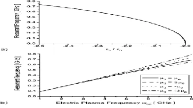
P a g e | 950 Fig. 7. (a) Variation of the resonant
frequency of the rectangular patch antenna of Fig.6 with W = 50mm, η = 0:5, ε1 = 2 ε0, µ1= µ2 = µ0 as a function of ε2 . (b)
the same as a function of the electric plasma frequency of a Drude-like dispersive metamaterial for the second medium, varying also its permeability µ2 as a parameter. In particular, Fig. 7(a) shows the variation of the resonant frequency with assuming µ2=µ0, whereas Fig. 7(b) shows resonance frequency variation versus the plasma frequency the resonance frequency variation versus the plasma frequency wep assuming a Drude dispersive material for the permittivity of the loading ENG material, i.e. In this second case µ2, is also varied as a parameter.
When the filling material is homogeneous, i.e. ε1 = ε2 = 2 ε0 , the patch has its resonance at f=w/2π =2.12GHz. However, loading the patch with an ENG material can reduce the resonance frequency in principle without limits, as shown in Fig. 7(a). Fig. 7(b) relates this variation to the plasma frequency of a Drude-like dispersive material. This
has been adopted to model the realistic dispersion of an ENG metamaterial made by embedding specific inclusions inside a host material. Also in this case, properly varying the size and shape of the inclusions that form the second filling material. in order to approach the effective permittivity of ε2 = -2 ε0, the resonance frequency may in principle be brought down arbitrarily. These results, as Fig. 7(b) shows, are weakly affected by the permeability of the second material µ2, and this dependence becomes irrelevant when the resonant frequency is reduced, since the quasi-static approximation represented by (19) holds. A filling material with high electric permittivity may be employed instead of such plasmonic metamaterial.
P a g e | 951 however, is intrinsically limited by the
fact that a higher permittivity usually accompanies higher losses and the presence of surface waves, and reducing the resonance frequency to very low values would require the use of extremely high permittivities. On the other hand, the resonance is not obtained by adjusting the wavelength in the filling material, but instead by inducing a plasmonic resonance at the interface underneath the patch, which allows a phase cancellation similar to the effect predicted in [4]. This point is further clarified in Fig. 8, which shows the electric and magnetic field distribution at resonance predicted by the cavity model for the patch considered in Fig. 7 for the three cases when: (solid line) ε2 = 2 ε0, , i.e., when the substrate is homogeneous and the patch resonates at f = 2.12GHz; (dashed line) for a second material chosen according to (7) to lower the patch resonance to f = 0.5 GHz, i.e., using a material with ε2 (f = 0.5GHz)= -2.2 ε0 ; (dotted line) for a second material with its permittivity increased so that the patch can resonate at the frequency f =
0.5GHz, i.e., with ε2 = 140 ε0.
The magnetic field amplitudes have been normalized in the fig 8 to their relative maximum and the electric field are normalized accordingly for comparison. As it can be seen, the three cases show very different properties. The standard resonance of the patch would happen at f = 2.12GHz, as the solid line shows.
At this frequency the patch width is 0.5 λ, with λ being the wavelength inside the homogeneous material loading the patch.
As it is well known, the magnetic field in fact experiences a half-wavelength sinusoidal variation from one side to the other of the patch, whereas the electric field flips its sign, with a 1800 phase variation. Filling the region y>0 with a material with ε2 (f = 0.5GHz) = -2.2 ε0 allows getting a resonance at f = 0.5GHz , as shown by the dashed line.
In this case the magnetic field flips the sign of its derivative, due to the boundary conditions at the interface between the two “oppositely signed” materials, and this allows to shrink the electrical dimensions of the equivalent cavity. As clearly seen in the figure, the electric field variation in this case is almost constant and its phase does not flip passing from one side to the other of the patch.
This affects the radiation properties of the patch. Employing a high-dielectric material (dotted line), the resonance frequency is made low by decreasing the wavelength in the material in y>0, which in fact is responsible for almost all the sinusoidal variation of the magnetic field.
The electric field remains almost constant in the left material, but experiences a 1800 phase shift in the material with high permittivity. The well-known cause of
radiation is represented by the fringing electric field at the two sides of the patch,
i.e., at y = ± ½ w. They correspond to the equivalent magnetic currents k=
2 /
ˆ
w y
E n
, where E is the electric
P a g e | 952 the cavity model, and is the normal to the
side of the patch, i.e. nˆ xˆ respectively. In the solid and dotted line cases, i.e.,
when the cavity is resonating in a conventional way, the electric field on the two sides of the patch is oppositely oriented, and therefore the two sides of the patch radiate in phase towards broadside this ensures the conventionally shaped radiation pattern of the patch antenna, with reasonable directivity at broadside. In the dot-line case, when a high permittivity is employed to squeeze the patch width, we may expect a lower directivity, due to the reduced electrical distance between the two radiating edges, and a lowered gain caused by the presumably strong excitation of surface waves, due to the presence of a high- substrate. Also the potential presence of high losses in such material would contribute to deterioration of its radiating performance. When the patch is loaded with a metamaterial, however, the mode excited (dashed line) will cause the two sides of the patch to radiate out of phase. Due to the electrically small dimensions of the patch, moreover, the two magnetic currents almost cancel each other for all the visible angles, and thus the radiation efficiency of such an antenna would be very poor. Another aspect should also be considered: the interfaces at y=0 and
support surface plasmons, since they are interfaces between media with materials with opposite permittivities [12]. If the plasmonic resonance at is the main factor responsible for the sub-wavelength
resonance, these surface plasmons, when excited, would eventually trap some energy from the source, thus further reducing the radiation efficiency of the antenna.
V.NUMERICAL ANALYSIS
As a first example, behavior of the rectangular patch antenna of Fig. 7 is atudied, with W = 50 mm.,L=40 mm
,h=1.5mm, η = 0:5, ε1 = 2 ε0, µ1= µ2=µ0 , properly loaded with a Drude dispersive and lossy ENG material with ε2(ω) = ε0 (1-ω2
ep/[ ω(ω-j ωτ) ] ) . The plasma frequency
P a g e | 953 Fig.9 . Full-wave numerical
simulation results for (a) return loss and (b) input impedance of the antenna in Fig. 7 with a Drude material with losses, fed by a coaxial cable, as described in the text.
The sub-wavelength resonance in this case is poorly matched.
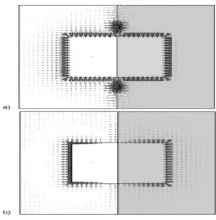
Fig.10 (Results calculated using CST Microwave Studio [13]). Electric field distribution (snapshot in time, top view) at the first two resonant frequencies for the
antenna of Fig. 9: at (a) f = 0:48 GHz and (b) f = 2:44 GHz.
Fig. 10 reports the electric field distribution for these two different resonance frequencies on the plane of the patch.
This clearly shows how the fringing fields are oppositely directed in the sub-wavelength case, different from the usual resonance at f = 2.44GHz. The field distributions are consistent with the cavity model analysis described in the previous section and confirm the different behavior of the field at the radiating edges at the two frequencies, highlighting also the standing waves present at the interface y =
0 due to the excitation of surface plasmons. The radiation patterns in the two cases are substantially different, since at the lower frequency the patch is not radiating properly and it shows a nullat broadside and an insufficient gain over all the visible angles.
This rectangular configuration at the frequency f = 0.48GHz ends up being a good candidate for a matching network for the excitation of surface plasmons at the interface y = 0 rather than as a good radiator.
VI. CONCLUSION
P a g e | 954 simulations, considering material
dispersion, losses and the presence of the feeding network have been also presented, providing a validation of the theoretical results and showing how a practical realization is foreseeable. While as with the equilateral triangular microstrip antenna with microstrip feed it is found that 35.5% of space can be save is constructing ETMP structure. This may indeed open interesting venues for the design of small-scaled antennas with enhanced performance.
Fig.11.Comparison of occupied aperture area of
rectangular & triangular patch configuration:
h=1.6mm & εr=2.22 at fr =1325 MHz.
VII. REFERENCES
[1] D. M. Pozar and D. H. Schaubert, Microstrip Antennas: The Analysis and Design of Microstrip Antennas and
Arrays. New York: IEEEPress, 1995.
[2] J. R. James and P. S. Hall, Handbook
of Microstrip Antennas.London, U.K.:
Peter Peregrinus, 1989.
[3] R. W. Ziolkowski and N. Engheta,
Eds., IEEE Trans. Antennas Propag.,
Special Issue on Metamaterials, vol. 51, pp. 2546–2750, Oct.2003.
[4] N. Engheta, “An idea for thin subwavelength cavity resonators using metamaterials with negative permittivity and permeability,” IEEE Antennas Wireless Propag. Lett., vol. 1, no. 1, pp.10–13, 2002.
[5] A. Alù and N. Engheta, “Guided modes in a waveguide filled with a pair of single-negative (SNG), double-negative (DNG), and/or double-positive (DPS) layers,” IEEE Trans. Microw. Theory Tech., vol. MTT-52, no. 1, pp. 199–210, Jan. 2004.
[6]“Polarizabilities and effective parameters for collections of spherical nano-particles formed by pairs of concentric double-negative (DNG), single-negative (SNG) and/or double-positive (DPS) metamaterial layers,” J.
Appl. Phys., vol. 97, May 1, 2005,
094310.
[7] K. R. Carver and J. W. Mink, “Microstrip antenna technology,” IEEE
Trans. Antennas Propag., vol. AP-29, no.
1, pp. 2–24, Jan. 1981.
[8] W. F. Richards, Y. T. Lo, and D. D. Harrison “An improved theory of microstrip antennas with applications,”
IEEE Trans. Antennas Propag., vol.
AP-29, no. 1, pp. 34–46, Jan. 1981.
[9] L. Landau and E. M. Lifschitz,
Electrodynamics of Continuous Media.
Oxford, U.K.: Pergamon Press, 1984.
P a g e | 955 [11] J. B. Pendry, A. J. Holden, D. J.
Robbins, and W. J. Stewart, “Lowfrequency plasmons in thin wire structures,” J. of Physics: Condensed
Matter, vol. 10, pp. 4785–4809, 1998.
[12] J. D. Jackson, Classical
Electrodynamics. New York: Wiley,
1975.
[13] CST Microwave Studio 5.0 CST of America [Online].Available: http:// www.cst.com
[14] Microstrip Antenna Design
Handbook - R Garg, Prakash Bhartia,
Inder Bahl, A Ittipiboon
[15] The Handbook of Microstrip
Antennas - James R James
[16] Antenna Engineering Handbook - Richard C. Johnson.
[17]Powell's Books - Advances in Microstrip and Printed Antennas.