jls e- 2%.
{“;a$7,yL
/ 453
“/ ‘LCD
Part Number 247.8002-o824
INSTALLATION
AND
FIELD MAINTENANCE
MANUAL
Issue 1, June 1984
INTER-TEL PRACTICES
824 INSTALIATION & MAINTENANCE Issue TABLE OF CONTENTS 1, June 1984
TABLE OF CONTENTS
TABLE OF CONTENTS... . . . .
LIST OF FIGURES . . . ..I---..
FCC REGULATIONS . . . ~.______ --_-__ WARRANTY . . . ..-..
. I .
....---‘---...*. 111
. . . viii .I~~~~~~--_____ . . . x
. . . xii
OVERVIEW . . . l-l 1.
2.
3. 4.
,’ -1
‘\ 5.
INTRODUCTION ... l-1
HARDWARE SUMMARY ... l-l
A. Key Service Unit ... 1-2
B. Keysets...: ... l-2
C. Door-Mates ... 1-2
INSTALLATION SUMMARY ... l-2
MAINTENANCE SUMMARY ... 1-3
FEATURES AND PROGRAMMING SUMMARY ... 1-3
SYSTEM SPECIFICATIONS ..-...I... . . . 2-l
1.
2. 3. 4. 5.
6. 7.
\ 8.
9.
INTRODUCTION ... 2-1
824 KEYSETS ... 2-2
DOOR-MATES ... 2-3
EQUIPMENT DIMENSIONS ... 2-3
KEY SERVICE UNIT (KSU) ... ... ... 2-3 ..- ..
A. KSU Description...'.. ... 2-3
B. Power Supply ... 2-4
C. Environmental Requirements ... 2-4
D. Central Office (C.0.) Line Characteristics ... 2-4
E. Printed Circuit Boards (PCB's) ... 2-5
MAIN DISTRIBUTION FRAME (MDF)...,... 2-8
SMDR AND PROGMMING TERMINAL REQUIREMENTS... 2-8
BATTERY BACK-UP ... 2-9
SYSTEM FEATURES CAPACITIES ... 2-b
INTER-TEL PRACTICES TABLE OF CONTENTS
824 INSTZUJATION & MAI- Issue 1, June 1984
DIAGNOSTIC PROGRAMMING . . . 5-1 1.
2. 3. 4. 5.
INTRODUCTION ... 5-l
KEYSET (KTs) MONITOR (4) ... 5-2
STATION (STN) MONITOR (5) ... 5-2
C.0. MONITOR (6) ... 5-3
STATION SET-UP DATA (7)..* ... 5-4
TROUE3LEtSHOOTII!ZG . . . 6-1
1. INTRODUCTION... 6-1
2. .DEFECTIVE UNIT RETURN POLICY... 6-l
3. TROUBLESHOOTING PROCEDURE ... 6-2
A. Preliminary Troubleshooting Checklist ... 6-2
B. Light-Emitting Diode (LED) Indications ... 6-3
C. System Troubleshooting Procedures ... 6-6
REPLACliZ%ENT PARTS . . . 7-l
1. INTRODUCTION...~.. 7-l
2. ORDERING PROCEDURE...:... 7-l.
3. REPLACEMENT PARTS LIST... 7-1
4. RECOMMENDED SPARE PARTS... 7-1
FEATURES ... 8-l
INTRODUCTION TO FEATURES...: ... 8-l
SYSTEM FEATURES ... 8-2
1. INTRODUCTION...* ... 8-2
2. STATION MESSAGE DETAIL RECORDING (SMDR) ... 8-2
3. FLEXIBLE ATTENDANT ARRANGEMENTS ... 8-4
4. SELECTABLE RING (NIGHT ANSWER) ... 8-4
,
INTER-TEL PRACTICES TABLE OF CONTENTS
824 I~~TION & s Issue 1, June 1984
5.
6.
7.
8.
9.
POWER FAILURE CAPABILITIES ... 8-4
A. Battery Back-Up ... 8-4
B. Power Failure Transfer (PFT) Arrangement ... 8-5
C. Data Base Back-Up ... 8-5
DUAL-TONE MULTI-FREQUENCY (DTMF) OR DIAL
PULSE SIGNALLING ... 8-5
MUSIC-ON-HOLD ... 8-6
CALL PRIVACY ... 8-6
TOLL RESTRICTION ... 8-6
A. Toll Restriction Classes ... 8-7
B. WATS Line Access ... 8-7
C. Allowed Area Code List ... 8-7
D. Specialized Common Carrier (SCC) Access ... 8-7
E. Local Information Calls ... 8-8
. . i
10. DIRECT RING-IN LINES... . . . 8-8
11. VARIABLE TIME-OUT CAPABILITIES... 8-8
STATION FEATURES... 8-9
1. INTRODUCTION... . . . 8-9
2. KEYSET GENERAL FEATURES... 8-9
8-9 A. B. C. D. E. F. G. H.
Key Functions ... LED Indications ...
Audible Tone Indications ... Display Keysets ...
Volume and Ring Tone Control ... Call Number Buffering ...
Direct Incoming Line Flexibility ... C.O. Line Restrictions ...
8-11 8-13 8-14 8-14 8-14 8-14 8-14
3. INTERCOM FEATURES ... .8-15
A. Flexible Intercom Numbering ... 8-15
B. Voice Announcing ... 8-15
C. Handsfree Answering ... 8-15
D.' Station-to-Station Calling ... 8-15
E. Intercom Camp-On and Call Waiting ... 8-16
INTER-TEL PRACTICES TABLE OF CONTENTS
824 INST~ION & s Issue 1, June 1984
4. OUTSIDE CALL (C.O.) FEATURES ... 8-17
A. Placing and Receiving Outside Calls ... 8-17
B. Alternate Methods for C.O. Line Selection ... 8-18
C. Alternate Methods of Dialing, ... 8-21
D. Calls On Hold ... 8-26
E. Transferring Outside Calls ... 8-27
2
Recall Timers ... 8-28
Reverse Transfer ... 8-29
H. Conference Calls ... 8-29
I. C.O. Call Waiting ... 8-31
5. SPECIAL STATION FEATURES ... 8-32
A. Call Forwarding ... 8-32
B. Do-Not-Disturb ... 8-33
C. Paging Features ... 8-33
D. Long Speech Warning ... 8-34
E. Selectable Ring (Night Answer) ... 8-35
F. Door-Mate ... 8-35
6. SPECIAL DISPLAY KEYSET FEATURES ... 8-36
A. Remote Contacts ... 8-36
B. Absent Mode ... 8-36
C. Message Registration ... 8-37
D. Keyset Status Checks ... 8-39
E. Silent Calls ... 8-39
INTER-TEL PRACTICES LIST OF FIGURES
824 INSTALWiTION 6r s Issue 1, June 1984
LIST OF FIGURES
NUMBER TITLE PAGE
SYSTEM SPECIFICATIONS
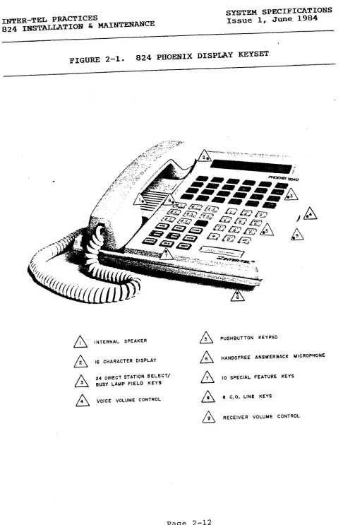
Figure 2-1. 824 Phoenix Display Keyset ... 2-12
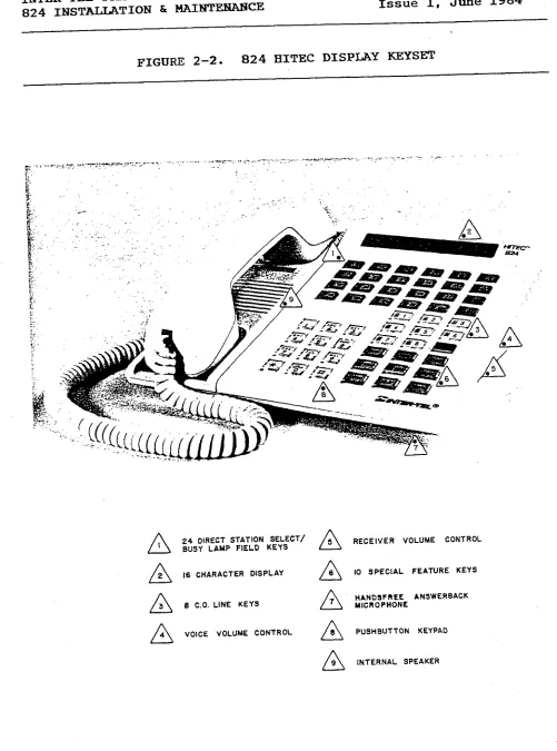
Figure 2-2. 824 Hitec Display Keyset ... 2-13
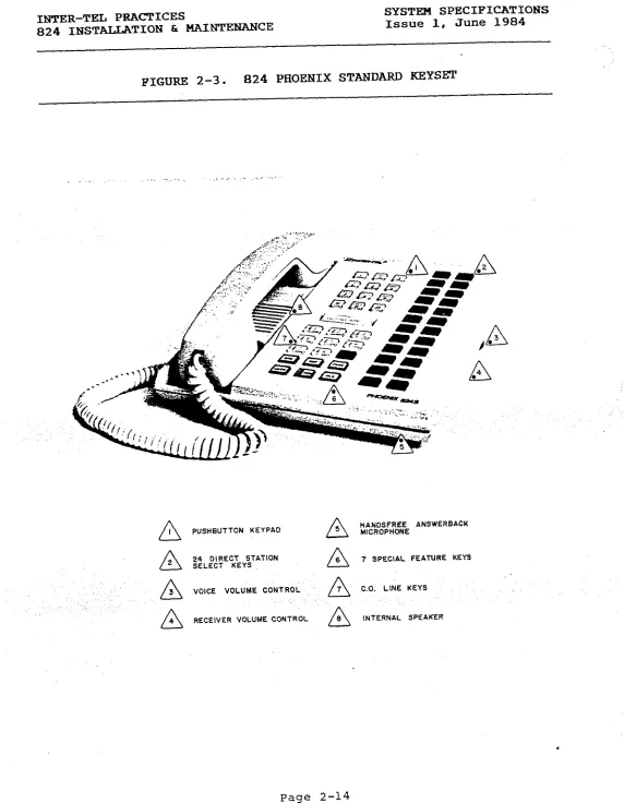
Figure 2-3. 824 Phoenix Standard Keyset ... 2-14
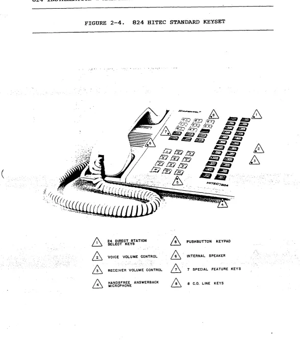
Figure 2-4. 824 Hitec Standard Keyset ... 2-15
Figure 2-5. Door-Mate ... 2-16
Figure 2-6. Key Service Unit (KSU) ... 2-17
INSTALLATION
Figure 3-l. Keyset Modular Jack Assembly Wiring ...
Figure 3-2. Main Distribution Frame (MDF) Layout ...
Figure 3-3. C.O. Line Terminations on the MDF ...
Figure 3-4. Station Cable Terminations ...
Figure 3-5. Station Cable Terminations on the KTI Block ....
Figure 3-6. Miscellaneous Terminations on the MISC Block ...
Figure 3-7. System Power Supply ...
Figure 3-8. Power Supply Connections on the Backplane ...
Figure 3-9. Main Distribution Frame (MDF) PCB ...
Figure 3-10. Central Processor Unit (CPU) PCB ...
Figure 3-11. 4-CO1 Central Office Interface PCB ...
Figure 3-12. 2-CO1 Central Office Interface PCB ...
Figure 3-13. CO1 Jumper PCB ...
Figure 3-14. 8-KTI Key Telephone Interface PCB ...
Figure 3-15. 4-KTI Key Telephone Interface PCB ...
Figure 3-16. Miscellaneous (MISC) PCB ... Figure 3-17. Door-Mate (DOOR) PCB ...
Figure 3-18. KSU Cabling from MDF Backboard to MDF PCB ...
Figure 3-19. Keyset Power Cable Stress Relief Strap ...
Figure 3-20. Wall Mounting Hitec Keysets ...
Figure 3-21. Wall Mounting Phoenix Keysets ...
Figure 3-22. 824 Hitec Keyset Bottom ... Figure 3-23. 824 Phoenix Keyset Bottom ...
Figure 3-24. 824 Standard Keyset Control Board ...
Figure 3-25. 824 Display Keyset Control Board ...
Figure 3-26. Wall Mounting the Door-Mate ... Figure 3-27. Door-Mate Bottom ...
;I;
3-7 3-9
3-10 >
3-12 3-17 3-18 3-21 3-23 3-25 3-26 3-27 3-29 3-30 3-32 3-33 3-35 3-37 3-38 3-39 3-40 3-41 3-42 3-43 3-45 3-46
INTER-TEL PRACTICES TABLE OF CONTENTS
824 INSTATXATION & s Issue 1, June 1984
INSTALLATION. . . ..-... 3-l 1.
2.
3.
4.
5.
6. 7. a. 9.
INTRODUCTION ... 3-l
SITE PLANNING ... 3-1
A. Key Service Unit (KSU) Site Planning ... 3-2
B. Tools and Supplies Required ... 3-3
CABLING ... 3-3
A. Running Cable ... 3-4
B. Modular Jacks... ... 3-4
ASSEMBLING THE MAIN DISTRIBUTION FRAME (MDF) BACKBOARD . . 3-5
A. Connecting C.O. Lines to the MDF ... 3-6
B. Connecting Station Cables to the MDF ... 3-8
C. Connecting Door-Mates and External Equipment
to the MDF ... 3-11
D. Loop Resistance Tests ... 3-13
KEY SERVICE UNIT (KSU) INSTALLATION ... 3-15
A. Unpack the Equipment ... 3-15
B. Power Supply Installation ... 3-15
C. Printed Circuit Board (PCB) Installation ... 3-20
D. Complete the KSU Installation ... 3-34
KEYSET INSTALLATION ... 3-36 .
DOOR-MATE INSTALLATION ... 3-44
BATTERY BACK-UP INSTALLATION ... 3-47
INSTALL THE SMDR OUTPUT DEVICE ... 3-48
10. INSTALL EXTERNAL MUSIC-ON-HOLD... . . . 3-49
SYSTEM PROGRAMMING ..-...-... . . 4-l
1. INTRODUCTION... . . . 4-1
2. PROGRAMMING METHODS ... 4-2
A. Programming Terminal ... 4-2
B. Maintenance Panel ... 4-3
3. SYSTEM PROGRAMMING ... 4-5
A. Initial Programming Outline ... 4-5
B. Program Planning Sheets ... 4-5
C. System Initialization ... 4-6
D. Using the Maintenance Panel ... 4-7
E. Using the Programming Terminal ... 4-17
.
INTER-TEL PRACTICES 824 IFKZl!~TION & BE
LIST OF FIGURES
Issue 1, June 1984
SYSTEM PROGRAMMING
Figure 4-1. CPU Maintenance Panel ... 4-4
Figure 4-2. Function Switch Programming ... 4-8
Figure 4-3. Programming Terminal Program Planning Sheet .... 4-24
Figure 4-4. Function Switch Program Planning Sheet ... 4-25
Figure 4-5. Toll Restriction Table ... 4-28
DIAGNOSTIC PROGRAMMING
Figure 5-l. Keyset (KTS) Monitor Display Data ... 5-5
Figure 5-2. Station (STN) Monitor Display Data ... 5-6
Figure 5-3. C.O. Monitor Display Data ... 5-8
Figure 5-4. Station Set-Up Data ... 5-9
TROUBLESHOOTING Figure 6-l.
Figure 6-2. Figure 6-3. Figure 6-4. Figure 6-5. Figure 6-6.
Light-Emitting Diode Indications... 6-4
LED Locations... 6-5
Feature Failure Troubleshooting Chart...,.. 6-7
Internal Communications Troubleshooting Chart.. 6-9
External Communications Troubleshooting Chart.. 6-11
System Malfunctions Troubleshooting Chart... 6-12
REPLACEMENT PARTS
Figure 7-l. Replacement Parts ... 7-2
Figure 7-2. Recommended Spare Parts ... 7-4
FEATURES
Figure 8-1. SMDR Printout ... 8-3
Figure 8-2. Available Timers ... 8-8
Figure 8-3. Key Functions ... 8-10
Figure 8-4. LED Indications.& ... 8-12
INTER-TEL PRACTICES FCC RJZGULATIONS
824 INSTALJATION Et MAIblTENANcE Issue 1, June 1984
FCC RJZGULATIONS
IMPORTANT:
1. Customers connecting this equipment to the telephone network
shall, before such connection is made, give notice .to the
telephone company of the particular line(s) to which such
connection is to be made, and shall provide the telephone
company with the following information:
- FCC Registration Number, BE287V-13275-MF-E
- Ringer Equivalence Number, 0.8A
- Type of jack to be ordered from the telephone
company, RJ-21X or RJ-14C
The telephone company should also be given notice upon final
disconnection of this equipment from the particular line(s).
It is also the responsibility of the customer to provide the
telephone company with registration numbers of any other
devices which are configured for connection to the telephone
network.
2. It is prohibited by the telephone company to make connections
to party lines or to a coin telephone service. i
3. Under certain circumstances the telephone company may tempo-
rarily discontinue service and make changes in facilities and
services which may affect the operation of this equipment;
however, the customer shall be given adequate notice in
writing to allow the customer an opportunity to maintain
uninterrupted service.
4. Users should not make adjustments,
service this equipment.
repairs or attempt to
In the event that a problem origi-
nates, contact the local authorized factory service
representative. i ._
'. .., . . . z ~:,-In.the event.of trouble with the,telephone ,line(s) this
equipment must be disconnected from the telephone l<ne(s).
If trouble ceases,
authorized factory service the equipment representative. must be repaired If the trouble. by an
continues to occur with the equipment disconnected, the
telephone company should be notified that they have a
problem. If this is the case, repairs or adjustments made by
the telephone company will be made at their expense.
INTER-TEL PRACTICES FCC REGULATIONS
824 INSTALLATION & s Issue 1, June 1984
WARNING:
This equipment generates and uses radio frequency energy and if
not installed and used properly, that is, in strict accordance
with the manufacturer's instructions, may cause interference to
radio and television reception. It has been type tested and
found to comply with the limits for a Class A computing device in
accordance with the specifications in Subpart J of Part 15 of FCC
Rules, which are designed to provide reasonable protection
against such interference in a residential installation. How-
ever, there is no guarantee that interference will not occur in a-
particular installation. If this equipment does cause inter-
ference to radio or television reception, which can be determined
by turning the equipment off and on, the user is encouraged to
try to correct the interference by one or more of the following
measures:
- Reorient the receiving antenna
- Relocate the computer with respect to the receiver
- Move the computer away from the receiver
c
- Plug the computer into a different outlet so thatcomputer and receiver are on different branch circuits.. .,
If necessary, the user should consult the dealer or an experi-
enced radio/television technician for additional suggestions.
The user may find the following booklet prepared by the Federal
Communications Commission helpful:
"HOW to Identify and Resolve Radio-TV Interference"
This booklet is available from the U.S. Government Printing
Office, Washington, D.C. 20402, Stock No. 004-000-00398-5.
.Y.,
,. /;
. . . -’
,i .’ :. ‘a :, -;.
\
.
INTER-TEL PRACTICES OVERVIEW
824 II!JSTALLATION & MAIWl!ENANCE Issue 1, June 1984
OVERVIEW
CONTENTS PAGE
1. 2. 3. 4. 5.
1.
INTRODUCTION ... l-l
HARDWARE S-Y ... l-1
IHSTALLATION SUMMARY ... 1-2
MAINTENANCE S-Y ... 1-3
FEATURES AND PROGRAMMING SOMMARY... l-3
INTRODUCTION
1.01 The 824 system is a versatile electronic key telephone sys-
tem designed to meet the needs of growing businesses. Modular
design makes the system easy to install and service, and the pro-
grammable features provide a variety of services to meet each
customer's needs. The system has capacity for eight Central
Office (C.O.) lines, 24 stations, two intercom paths, and one
path for paging.
1.02 This manual, geared especially to service personnel, ex-
plains installation, programming, operation and maintenance of
the system.
1.03 Another Inter-Tel publication for this system is the 824
Owner's Guide (part number 247.8001-o). Its purpose is to pro-
vlde the user and sales person with an overview of the system
hardware and a complete operation manual.
2. HARDWARE SUMMARY
2.01 The SYSTEM SPECIFICATIONS section of this manual describes
the hardware. As a brief introduction, this section includes the
Key Service Unit (KSU), Keysets, and Door-Mates.
.
INTER-TEL PRACTICES OVERVIEW
824 INSTALLATION h MAINTENANCE Issue 1, June 1984
,,'
A. KEY SERVICE UNIT jKSU)
2.02 The Key Service Unit (KSU) houses the circuit boards and
the system power supply. The KSU performs all control and
switching activities for the system.
incoming calls,
This includes detecting
processing data-controlled features, and control-
ling the interaction between stations, C.O. lines, and intercom
paths.
B. KEYSETS
2.03 Four types of keysets are used on the 824 system. They
are the Standard Keyset, Display Keyset, and Display and Standard
Power Failure Transfer Keysets. The Display Keyset has a 16-
character liquid crystal display (LCD) for showing applications
in use, such as number dialed, keyset status, date and time,
messages, etc.
2.04 In case of power failure, special switching circuitry in
the KSU controls the switching of the C.O. lines to the appro-
priate Power Failure Transfer (PFT) Keysets. These PFT Keysets,
which are used as regular keysets during normal operation, allow
incoming calls to be answered during a power failure.
C. DOOR-MATES
2.05 The Door-Mate is an optional piece of equipment which can
be used as a talkback speaker in remote locations. Keysets are
programmed to answer or call the Door-Mate.
3. INSTALLATION SUMMARY
3.01 In addition to the SYSTEM SPECIFICATIONS section, the
INSTALLATION SeCtiOn gives complete instructions to plan the in-
stallation and install the system.
3.02 A floor plan should be developed in preparation for in-
stallation. The mounting board for the Main Distribution Frame
(MDF) should be made large enough to accommodate the Key Service
Unit (KSU), connectors, external equipment, and allow room for
expansion.
3.03 The KSU location should be planned in relation to its en-
vironment, power requirements,' and the length of the cabling
necessary to connect it to the stations.
.
INTER-TEL PRACTICES OVERVIEW
824 INSTALLATION br MAINTENANCE Issue 1, June 1984
3.04 The INSTALLATION section contains instructions for install-
ing the following:
l Cabling
l Main Distribution Frame (MDF) Cabling
l Key Service Unit (KSU)
l Keysets l Door-Mates
l Battery Back-Up
l Other External Equipment
4. MAINTENANCE SUMMARY
4.01 Service is designed for the modular level. In the event of
a failure, the defective module should be replaced by the service
personnel from their inventory of spare parts.
4.02 All lamps used in the system are solid state, Light-Emit-
ting Diodes (LED'S). The use of LED's greatly reduces the possi-
bility of burned out components, due to their low failure rate
and minimal power consumption.
4.03 This manual contains a TROUBLESHOOTING section and a
DIAGNOSTIC PROGRAMMING section to aid service personnel in diag-
nosing system problems. The REPLACEMENT PARTS section lists
parts available from Inter-Tel.
4.04 Strict quality assurance standards for manufacturing and
through field testing provide the system with the high degree of
reliability demanded by today's high-technology market.
5. FEATURES AND PROGRAMMING SUMMARY
5.01 The FEATURES section of this manual provides an in-depth
explanation of the available features. The SYSTEM PROGRAMMING
section provides complete programming procedures. If a feature
requires programming or additional equipment, this information 1s
given. ..'
5.02 Features requiring additional hardware include: Station
Message Detail Recording (SMDR), Door-Mates, remote contacts,
external Music-On-Hold, battery back-up, and external paging.
5.03 Programming is performed through a programming terminal and
through the CPU PCB Maintenance Panel. Available features in-
clude:
.
INTER-TEL PRACTICES
824 INSTALLATION Sr MAINTENANCE
OVERVIEW
Issue 1, June 1984
proqramminq Terminal
l Station Speed Call List
l Keyset Monitor
0 Station Monitor
0 C.O. Line Monitor
0 Station Set-Up Data
l Toll Restriction Programming
l Name Registration l Message Registration
.O Flexible Ringing Arrangement
l Immediate Ringing
l Four Toll Restriction Classes
l Account Codes on Station Message Detail
CPU Maintenance Panel
0 C.O. Line Equipping
l DTMF or Dial Pulse Signalling
0 Incoming Ring Tone
l FAX Line
l CES Ring Identification
l PBX Access Code
0 Intercom Number Assignment
l Door-Mate Answering/Selectable Ring
l Handsfree Answering/Voice Announcing
l System Hold and I-Hold
a Page Zones
l Long Speech Warning
l Toll Restriction Classes
0 C.O. Line Restriction
0 Direct Ring-in on C.O. Lines
l Calendar and Clock Settings
0 System Speed-Dial Number Clear
l Station Speed-Dial Number Clear
0 Conference Calls
l Auto Key Feature
l Hold Recall Timer
l Transfer Recall Timer
l Dial Tone Enable/Disable
0 "Meet Me" Page and Intercom
0 Station Message Detail Recording (SMDR)
Recording (SMDR)
,’ .
INTER-TEL PRACTICES SYSTEM SPECIFICATIONS
824 INSTALLATION & MAINTENANCE Issue 1, June 1984
SYSTEM SPECIFICATIONS
CONTENTS PAGE
1. 2. 3. 4. 5.
6.
c
7.8. 9.
1. INTRODUCTION
INTRODUCTION ... 2-l
824 KEYSETS ... 2-2
DOOR-MATES ... 2-3
EQUIPMENT DIMENSIONS ... 2-3
KEY SERVICE UNIT (KSU) ... 2-3
A. KSU DESCRIPTION ... 2-3
B. EXHER SUPPLY ... 2-4
C. ENVIRONMENTAL REQUIREMENTS ... 2-4
D. CENTRAL OFFICE (C.O.) LINE CHARACTERISTICS ... 2-4
E. PRINTED CIRCUIT BOARDS (PCB'S) ... 2-5
MAIN DISTRIBUTION FRAME (MDF) ... 2-8
SMDR AND PROGRAMMING TERHINAL REQUIREMENTS ... 2-8
BATTERY BACK-UP ... 2-9
SYSTEM FEATURE CAPACITIES ... 2-11
1.01 The 824 system can be configured with 8 C.O. lines and 24
keysets. The whole system operates from theKey Service Unir
Four keyset models are available, including Standard and Display
keysets, and Standard and Display keysets with Power Failure
Transfer. Optional hardware features include Door-Mates, Station
Message Detail Recording output device, battery back-up, external
paging, external music, .and remote contacts.
1.02 Hardware comprising the entire system is described in this
section of the manual. In addition, Section 9 lists system fea-
tures which have "capacities" (or quantity limits). Photographs
of the keysets, Door-Mate, and Key Service Unit are located at
the end of this section. For installation methods, refer to the
INSTALLATION section.
INTER-TEL PRACTICES SYSTEH SPECIFICATIONS
824 INSTALLATION & MAINTENANCE Issue 1, June 1984
2. 824 KEYSETS
2.01 A maximum of 24 keysets may be connected to the KSU. Stan-
dard and Display keyset models are available, and both may be
equipped as Power Failure Transfer units. For photographs, refer
to Figures 2-1 and 2-4 on pages 2-12 and 2-15. Keysets are fur-
ther described in the STATION FEATURES section.
2.02 All keysets are equipped with a pushbutton keypad, eight
C.O. line keys, an internal speaker, voice volume control, and a
6dB receiver volume control. The Standard keysets have seven
feature keys, while the Display keysets have ten. Both models
have 24 Direct Station Selector (DSS) keys, and for Display
keysets the DSS keys are
Lamp Field (BLF), indicating equipped station with status. LED's to serve as a Busy
2-03 Display keysets have a liquid crystal display (LCD), which
shows up to 16 characters. When in use,
time, number dialed, messages, intercom call the indications, display shows station date,
status, among other applications.
2.04 The Power Failure Transfer (PFT) feature was developed so
the system could receive incoming calls during power outages.
Under normal conditions, PFT keysets operate like regular key-
sets. When AC power is lost and battery back-up is not provided
or has been drained, the system automatically switches to the
Power Failure mode: calls in progress are dropped. Incoming
calls ring in directly to the PFT keysets.
2.05 The system assigns one C.O. line to one PFT keyset, in
circuit number order, with a maximum of eight per system (not to
exceed the number of C.O. lines equipped). The eight C.O. lines
are assigned to the first eight station circuits. For example,
C.O. circuit 1.1 will ring in on station circuit 1.1, C.O. cir-
cuit 1.2 will ring in on station circuit 1.2, etc.
2.06 Two optional devices are available for the keysets. All
keysets may be equipped with a plastic
number 828.1008) which extends up from the instruction back of stand the keyset. (part
This stand is approximately three inches wide and will hold note
cards. Available for the Phoenix keyset models is a card direc-
tory (part number 809.1092). This device is installed on the
bottom of the keyset. A tab extending out on the side of the
keyset is used to pull this directory pad out. The user may
write in telephone numbers or intercom numbers.
: . . .
INTER-TEL PRACTICES SYSTEM SPECIFICATIONS
824 INSTALLATION & MAINTENANCE Issue 1, June 1984
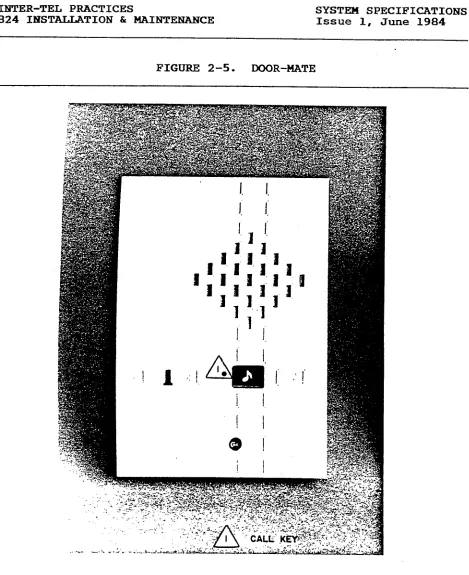
3. DOOR-MATES
3.01 The Door-Mate is an optional piece of equipment which is
used to monitor remote areas and serves as a talkback unit. Two
units may be installed and keysets must be programmed to access
them. When someone rings a Door-Mate, it is identified to sta-
tion users by its own melody.
Range" and Door-Mate #2 plays "Greensleeves". Door-Mate #l plays Volume "Home on the is con-
trolled on the DOOR PCB. Refer to Figure 2-5 on page 2-16.
4. EQUIPMENT DIMENSIONS
KSU Dimensions Keyset Dimensions Door-Hate Dimensions
Height 19 in. Height 3 in. Height 1.5 in.
Width 14 in. Width 8.5 in. Width 4 in.
Depth 9 in. Depth 8.5 in. Depth 5.5 in.
Weight 30 lbs. Weight 5 lbs. Weight 1.5 lbs.
5. KEY SERVICE UNIT (KSU)
(
A. KSU DESCRIPTION5.01 The KSU houses the system power supply, nine-slot cardfile,
and printed circuit boards (PCB's). It performs all control and
switching activities for the system, detects incoming calls,
processes data-controlled features, and controls the interaction
between keysets, C.O. lines, and intercom paths. Although the
KSU may be mounted on a shelf, Inter-Tel recommends to wall mount
it. Refer to Figure 2-6 on page 2-17.
5.02 The system is a microprocessor-controlled, space division
system. Memory includes 48K bytes ROM and 14K bytes RAM on the
Central Processor Unit (CPU) printed circuit board (PCB). Each
keyset contains a four-bit microprocessor that communicates with
the main microprocessor on the CPU PCB.
5.03 The KSU contains PCB's which control and coordinate the
functions of the system. Up to nine PCB's may be installed,
depending on the system's configuration; only one PCB is
optional. Each PCB is described in Section E.
1 Central PrOCeSSOr Unit (CPU) PCB
2 Central Office Interface (COI) PCB's
3 Key Telephone Interface (KTI) PCB's
1 Main Distribution Frame (MDF) PCB
1 Miscellaneous (MISC) PCB
1 Door-Mate (DOOR) PCB -- optional
INTER-TEL PRACTICES
824 INSTALLATIOlY & MAINTENANCE SYSTEM SPECIFICATIOBs Issue 1, June 1984
B. POWER SUPPLY
5.04 The power
and Door-Mates.
commercial power
5.05 The power
supply provides power to the KSU-, all stations,
It requires a 105-125VAC, 60Hz, single-phase
source.
supply may be equipped with battery back-up to
- . - .
support the system during a power outage or "brown-out" condi-
tion. Refer to Section 8 for more information.
5.06 One fuse on the power supply has a 6A 250V value.
ing voltages and power outputs are as follows:
Operat-
+27vDc 3.2A maximum Keyset
+5VDC 1.5A maximum Logic Levels
NOTE : +5VDC is the only regulated voltage.
C. EXVIRONMENTAL REQUIREMENTS
Requirements Temperature
In Operation 32O to 80° F Humidity
(Non-Condensing)
20% to 85%
Altitude up to 10,000 ft.
In Storage 4O to 185O F 0% to 85%
up to 40,000 ft.
D. CENTRAL OFFICE (C.O.) LINE CHARACTERISTICS
Characteristics Protection
Loss from TELCO to C.O. lines OdB Tip-to-Ring 15OOV transient
Ringer Equivalence 0.8A To Ground 1500VAC RMS
Ringing Voltage 40-1OOVAC
;
INTER-TEL PRACTICES SYSTEM SPECIFICATIONS
824 INSTALLATION & MAINTENANCE Issue 1, June 1984
E. PRINTED CIRCUIT BOARDS (J?CB'S)
5.07 Descriptions of each printed
graphs of all PCB's are located in
board are given below. Photo-
the INSTALLATION section.
Central Processor Unit (CPU) PCB
5.08 The system's CPU PCB contains the main controlling micro-
processor and its associated control, logic, and memory circuits.
This includes the central processor with up to 48K bytes of ROM
I- storage, 14K bytes of RAM storage, system clocks, a battery for
data base protection, and a Maintenance Panel for system pro-
gramming.
5.09 The CPU PCB provides central software control for the KSTJ.
It functions under the control of a generic program, stored in
the ROM, which is activated when the system is initially pro-
grammed.
5.10 The Battery Jumper on the PCB is shipped in the open posi-
tion to protect the battery. It should be enabled during in-
stallation to protect the data base. If the 'battery is fully
charged, the data base will be protected for a maximum of 25
days. Allow two days for the battery to charge when installing
the system.
Central Office Interface (COI) PCB's
5.11 There may be two CO1 PCB's per system. There are two types
available, one with circuitry for two C.O. lines, and one with
circuitry for four. If 2-CO1 PCB's are installed, the PCB in-
serted into CO1 slot 1 is assigned lines 1 and 2, top to bottom;
slot 2 has lines 5 and 6. With 4-CO1 PCB's installed, slot 1 has
lines l-4 and slot 2 has lines 5-8.
5.12 Each circuit in the Ull sockets may be designated as a DTMF
or a Dial Pulse circuit by inserting the appropriate chip. DTMF
chips are assigned part number 4089; Dial Pulse chips have part
number 400994. A switch next to each chip must be set to DP for
Dial Pulse or PB for DTMF.
5.13 Each circuit has a 3dB C.O. line attenuation pad to reduce
the incoming signal on extremely hot lines.
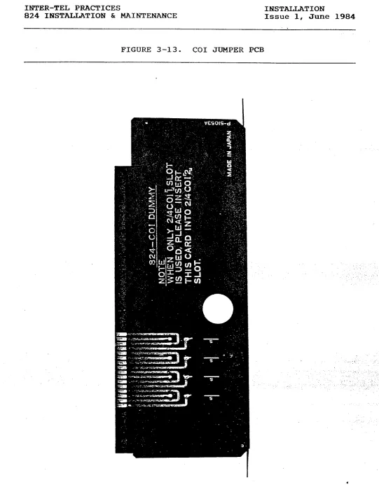
CO1 Jumper PCB
\
5.14 The CO1 Jumper PCB is inserted in the second COI slot when
only one CO1 PCB is installed. It provides the C.O. termination
to the backplane.
*
INTER-TEL PRACTICES SYSTEX SPECIFICATIONS
824 INSTALLATION & MAINTENANCE Issue 1, June 1984
i
Key Telephone Interface (KTI) PCB'S
5.15 There may be three KTI PCB's per system. There are two
types available; one with circuitry for four keysets and one with
circuitry for eight.
5.16 Each of the circuits on a KTI PCB is assigned a circuit
number by the PCB's physical location in the KSU and the location
of the circuit on the PCB. Intercom numbers are assigned when
the system is initialized, but may be changed. Refer to SYSTEM
PROGRAMMING.
5.17 A l.OA
shorts at the
protects the
fuses may be
ment.
power fuse on each KTI PCB protects the KSU from
stations. Fuse Fl, a 0.3A fuse on the speech path,
KSU from shorts on the tip and ring wires. The
obtained from Inter-Tel's Order Processing Depart-
Main Distribution Frame (MDF) PCB
5.18 The MDF PCB provides keyset connections, C.O. line con-
nections, a lack ' to attach the external music-on-hold source, an
RS232C communications port, and line separation switches. It
also includes connections for Door-Mates and external equipment.
For more information on the C.0. line, keyset, and Door-Mate
connections, refer to Section 6, MAIN DISTRIBUTION FRAME (MDF) on '
page 2-7.
5.19 A l/8-inch mini-phone connector on the front edge of the
MDF PCB is for an external music source.
5.20 A 25-pin subminiature "D" female connector on the front of
the MDF PCB is the RS232C communications port, used to attach the
programming terminal and the Station Message Detail Recording
(SMDR) output device. Refer to Section 7, SMDR AND PROGRAMMING
TERMINAL REQUIREMENTS'.
5.21 The line separation switches are used for, troubleshooting
C.O. lines. In order to verify a C.O. line connection, the
Master-Tel connection (on the MISC block of the MDF) is used with
the line separation switches (on the MDF PCB) to connect standard
2500 sets or technician's test sets. By pressing the switch for
the trouble line (l-8), it is disconnected from the system.
.
INTER-TEL PRACTICES SYSTEM SPECIFICATIONS
824 INSTALLATION & MAINTENANCE Issue 1, June 1984
5.22 The external equipment which can be installed with the
system are as follows:
A. The FAX line monitor allows the system to share a line
with the user's FAX machine. When the FAX machine is in
use, the system turns on the keyset LED for that line
number and denies access to that line.
B. Page Zone 9 provides voice output connection to the
customer-supplied external amplifier. The paging trans-
fer connection is a make/break connection dependent on
Zone 9 paging.
C. There are three remote contacts which serve as ON/OFF
switches. They may be connected to electrical devices
such as lights, security door locks, or sprinkler sys-
tems. They are accessed on Display keysets by pressing
the Remote (RMT) key and digits 1, 2 or 3.
Miscellaneous (MISC) PCB
c
5.23 The MISC PCB includes circuitry to select either the in-
ternal or external music-on-hold option: if internal music is
selected, there is circuitry to choose one of two synthesized
melodies. It also controls the external page volume, selects one
of two ringing tones for the keysets, and generates all tones
available in the system.
5.24 The MISC PCB provides an AGC circuit which automatically
holds the music-on-hold volume to a predetermined level that is
slightly lower than the normal voice volume, as required by FCC
regulations. Optimal input level is 1 VRMS.
5.25 Switch SW0 (EXT/MSC) is used to select internal/external
MOH. Switch SW1 (MSC A/B) selects one of two tunes for MOH.
Switch SW2 (HI/LG) sets the ring tone high or low on all keysets.
Door-Hate Interface (DOOR) PCB
5.26 If optional Door-Mate units are installed, 'the DOOR PCB
provides circuitry to connect up to the units. It includes a
volume control for the Door-Mate paging and talkback functions.
Door-Mates are terminated through the MISC block on the MDF and
the MDF PCB.
INTER-TEL PRACTICES SYSTEM SPECIFICATIONS
824 Il!iTSTALLATION & MAINTENANCE Issue 1, June 1984
6. MAIN DISTRIBUTIdN FRAMJZ (MDP)
6.01 Connections between incoming C.O. lines, keysets, and the
PCB's in the KSU are made on the Main Distribution Frame (MDF),
which is made up of industry-standard connection blocks.
6.02 First, two-pair cable is run to all keysets and is termi-
nated on four-conductor modular jack assemblies. The other end
of each cable is terminated on a designated MDF station (KTI)
block. Each KTI block supports up to 12 keysets.
6.03 Then one-pair cable is run to the two Door-Mate units. The
other end is terminated on the MDF's miscellaneous (MISC) block.
Other external hardware, such as paging equipment and remote
contacts, is also terminated on the MISC block.
6.04 Using a 25-pair cable, C.O. lines are connected to the MDF
C.O. lines block from the TELCO RJ-21X or RJ-14C connector.
6.05 Next, the KSU PCB's are connected to the MDF blocks. Four
special cables must be made. Using 25-pair cable, a 50-pin
female amphenol connector is attached to the KSU end of each
cable; the other end is terminated on the designated block--one
C.O. line block, two KTI blocks, and one MISC block. The inter-
face is completed by plugging the female connector into the
corresponding male connector on the MDF PCB. The MDF PCB com-
pletes the connection to the KTI, COI, MISC and DOOR PCB's.
7. SMDR AND PROGRAMMING TERMINAL REQUIREMENTS
7.01 The following requirements must be met for the SMDR output
device or a programming terminal to be connected to the system.
A. Both devices must be RS232C compatible and have a male
25-pin subminiature "D" connector.
B. Both must be formatted for serial ASCII with no parity
and must have full-duplex communications capability.
.,
C. Both devices must communicate at 300 baud.
INTER-TEL PRACTICES SYSTEM SPECIFICATIONS
824 INSTALLATION & MAINTEXANCE Issue 1, June 1984
8. BATTERY BACK-UP
8.01 Customer-provided batteries may be connected to the system
to prevent loss of service in the event of a power failure. When
the power supply off, the battery back-up function is automati-
cally connected. A warning bell or light can be hooked up to
signal the user when power drops.
*************************************************
* CAUTION *
* If the power supply ON/OFF switch is. turned *
* OFF, battery back-up is not enabled. To test *
* this feature, unplug the AC power cord. *
***~******************************************'***
8.02 The 824 system requires a 24VDC battery pack and must use
lead calcium grid batteries which have a 2.27V charge per cell.
To obtain 24 volts, batteries must be connected in series, must
be of the same type and have the same amp-hour rating, and must
have the same level of charge/discharge.
8.03 The batteries are trickle-charged by a float voltage of
27.3VDC. Calculation is made by multiplying the number of cells
(12) by the charge per cell (2.27V).
**************************f*ff****+****~*****
* CAUTION *
* Battery discharge time could vary depending
* on the battery manufacturer's specifications.
t *****t*******************************************
8.04 Two different battery sizes may be used. Battery back-up
is selected by setting the INTERNAL/EXTERNAL switch on the front
of the power supply. The EXTERNAL switch selects large batteries
which are connected outside of the KSU. The INTERNAL switch
selects small batteries which are mounted inside the K8lJ with the
brackets provided.
8.05 If you select the smaller batteries, you are limited to the
amount of system support available. Two 12VDC batteries may be
installed and the dimensions which fit the mounting brackets are
I-3/4" high, 2-5/8" wide, and 6" deep.
INTER-TEL PRACTICES
824 INSTALLATION & MAINTEXANCE
SYSTEM SPECIFICATIONS
Issue 1, June 1984
8.06 Before purchasing the batteries, calculate the amp/hour
rating. This is determined by the power needed to run the system
and the length of time the battery pack must support the system
if AC power fails. Calculate the rating as follows:
(1) Determine the minimum and maximum amounts of current
drawn by each PCB in the KSU, using the following cur-
rents. The minimum values represent the circuitry in an
idle condition (no calls in progress). Maximum values
represent the circuitry in an active condition. The CPU
figures include the current drain caused by the power
supply circuitry.
.
-.
PCB Minimum
bps)
Maximum (amps)
CPU . 136 ,138
4-KTI (4 Display keysets) .334 415
8-KTI (8 Display keysets) ,478 :595
2-co1 .085 . 087
4-CO1 .085 087
MISC . 110 :112
DOOR . 015 .017
(2)
(3)
Add the currents of all PCB's to determine the total
system current. Be sure to multiply the individual PCB
currents by the number of identical PCB's in the system.
Using the chart below, first locate the calculated bat-
tery current in the left column. Then move across in
that row until you reach the column with the desired
back-up hours. The figure shown is the battery amp-hour
rating to ask for when purchasing the batteries.
Battery Current (amps)
Back-Up Time (Hrs)
INTER-TEL PRACTICES
824 IBSTALIATION br MAINTENANCE SYSTEM SPECIFICATIONS Issue 1, June 1984
9. SYSTEM FEATURE CAPACITIES
9.01 Below is a summary of system feature capacities; that is,
features which have usage or installation limitations.
Keysets (maximum combinations)
Standard Keysets
Display Keysets
Power Failure Transfer Keysets
(Standard or Display)
Speech Channels
C.O. Lines
Intercom Paths
Paging Paths
Music-On-Hold Source
Features with Capacities
Paging
Internal Zone Page
External Zone Page
All-Page Speed Calling
System Lists
Station Lists
Numbers per System List
Numbers per Station List
Digits per Entry
Simultaneous 3-party Conference Calls
Queueing per C.O. Line
Call Waiting
2: '...
100 24 16
2 or 4 (See Note)
5 _
Intercom Call Waiting Initiated per Station
Intercom Calls Waiting at a Station
C.O. Calls Waiting at one Station
Toll Restriction
Allowed Area Codes
Classes of Service
Designated "WATS" 'Lines
1 1 8 30
,4 ‘.
8 -_
NOTE: The number of simultaneous conferences depends on the type
There can be a maximum of two simultaneous
of conference.
conferences if
party, because
conference has
it is possible
the eight C.O.
24 24 24 8 8 2 1 1 3 1 1
each has two inside parties and one outside
it uses the two intercom paths. If each
one inside party and two outside parties,
to have four simultaneus conferences, using
lines available.
INTER-TEL PRACTICES
824 I?!ZSTALLATION & MAINTENANCE
SYSTEM SPECIFICATIONS
Issue 1, June 1984
FIGURE 2-1. 824 PHOENIX DISPLAY KEYSET
a I
INTERNAL SPEAKER
a 2
16 CHARACTER DISPLAY
a
24 DIRECT STATION SELECT/ 3 BUSY LAMP FIELD KEYS
a 4
VOICE VOLUME CONTROL
a 5 pUSHBUTTON KEYPAO a 6
HANDSFREE ANSWERBACK MICROPHONE
a 7
10 SPECIAL FEATURE KEYS
a 6
8 C.O. LINE KEYS
n
9 RECEIVER VOLUME CONTROLINTER-TEL PRACTICES
824 INSTALLATION h MAI?ilT3==CE
SYSTEM SPECIFICATIONS
Issue 1, June 1984
FIGURE 2-2. 824 HITEC DISPLAY KEYSET
n 1
24 DIRECT STATION SELECT/ BUSY LAMP FIELD KEYSRECEIVER VOLUME CONTROL
16 CHARACTER DISPLAY IO SPECIAL FEATURE KEYS
8 CO. LINE KEYS
HANDSFREE ANSWERBACK MICROPHONE
VOICE VOLUME CONTROL PUSHEIUTTON KEYPAD INTERNAL SPEAKER
INTER-TEL PRACTICES
824 INSTALLATION & MAINTENANCE
SYSTEM SPECIFICATIONS
Issue 1, June 1984
FIGURE 2-3. 824 PHOENIX STANDARD IUZYSEZI!
PUSHBUTTON KEYPAD n 3 HANDSFREE MICROPHONE ANSWERBACK
A
04 OIRECT -...--. STATION n 7 SPECIAL FEANRE KEYS/2\ .%LECT KEY3 /‘\
A A - -ys
‘.
/\ 3 VOICE VOLUME CONTROL
/7\ C.O. LINE KE
RECEIVER VOLUME CONTROL INTERNAL SP EAKER
.
INTER-TEL PRACTICES
824 1NSTEU;LATION & MAINTENANCE
SYSTEM SPECIFICATIONS
Issue 1, June 1984
FIGURE 2-4. 824 HITEC STANDARD KEYSET
-I-. ,._ . . .z-..-. .I.
A I
A
2A 3
24 DIRECT STATION
SELECT KEYS A s PUSHBUTTON KEYPAD
. . . .
VOICE VOLUME CONTROL INTERNAL SPEAKER
.- _, , ._
RECEIVER VOLUME CONTROL 7 SPECIAL FEATURE KEYS HANDSFREE ANSWERBACK
MICROPHONE 6 C.O. LINE KEYS
INTER-TEL PRACTICES SYSTEM SPECIFICATIONS
824 INSTALLATION & MAINTENANCE Issue 1, June 1984
FIGURE 2-5. DOOR-MATE
. .
INTER-TEL PRACTICES SYSTEM SPECIFICATIONS
824 INSTALLATION b MAINTENANCE Issue 1, June 1984
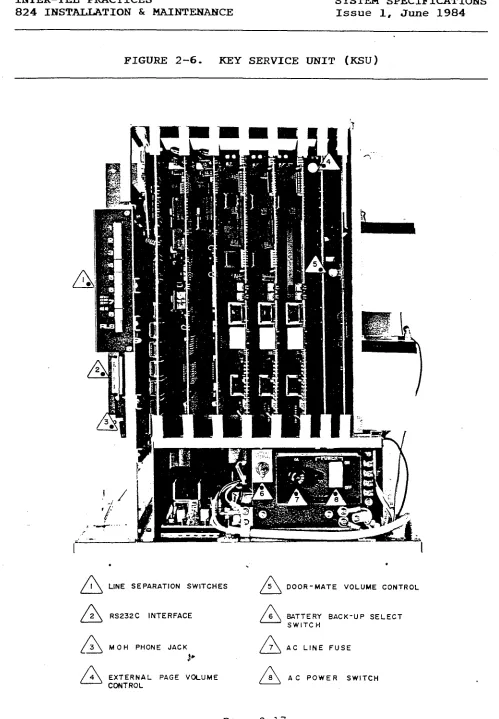
FIGURE 2-6. KEY SERVICE UNIT (KSU)
.
.
.
A I
LINE SEPARATION SWITCHESA 5 DOOR-MATE VOLUME CONTROL
n 2 RS232C INTERFACE n 6 BATTERY BACK-UP SELECT SWITCH
A 3 M OH PHONE JACK
L+ A
7 AC LINE FUSE
EXTERNAL PAGE VOLUME
A 6 AC POWER SWITCH CONTROL
INTER-TEL PRACTICES INSTALLATION
824 INSTALLATION & MAINTENANCE Issue 1, June 1984
I
INSTALLATION
CONTENTS PAGE
1.
2.
3.
4.
5.
6.
7.
8.
9. 10.
1. INTRODUCTION
INTRODUCTION ... 3-l
SITE PLANNING ... 3-l
CABLING ... 3-3
ASSEMBLING THE MAIN DISTRIBUTION FRAME (MDF) BACKBOARD . . 3-5
KEY SERVICE UNIT (KSU) INSTALLATION ... 3-15
KEYSET INSTALLATION ... 3-36
DOOR-MATE INSTALLATION ... 3-44
BATTERY BACK-UP INSTALLATION ... 3-47
INSTALL THE SElDR OUTPUT DEVICE ... 3-48
INSTALL EXTERNAL MUSIC-ON-HOLD ... 3-49
1.01 This section describes the recommended procedures for in-
stalling the 824 system hardware. It includes suggestions for
planning the installation, preparing the site, and providing the
necessary cable, connectors, jacks, etc. Refer to SYSTEM SPECI-
FICATIONS for hardware descriptions.
2. SITE PMING
2.01 Suggestions for planning the 824 installation are listed on
the next page. They include Key Service Unit (KSU) site planning
and tools and supplies required.
.
INTER-TEL PRACTICES INSTALLATION
824 INSTALLATION & MAINTENANCE Issue 1, June 1984
A. KEY SERVICE UNIT (KSU) SITE PLANNING
2.02 Prior to installing the 824 equipment, select a centralized
location for the KSU and Main Distribution Frame (MDF) which will
minimize cable run lengths from each station and provide the
proper environmental conditions.
A. Availability to 105-125VAC, 60Hz single-phase commercial
power.
NOTE : This must be a dedicated, separately fused AC in-
put for proper operation. It is highly recommended that
the ground wire also be dedicated to this outlet. All
three wires (power, neutral, and ground) should be run
directly from the breaker box to the KSU outlet.
B. Select the KSU location to minimize cable run length.
All keysets connected to the system must not exceed the
loop limit of 40 ohms or 800 feet (using 24 gauge wire).
Door-Mate units should not exceed the loop limit of 20
ohms or 400 feet.
C. The selected location should not be exposed to direct
sunlight, high humidity, heat radiation, dust, or strong
magnetic fields (such as heavy motors and large copy
machines). p
D. The maximum room temperature is 80°. The temgerature
r'ange inside the KSU must be within 32O to 104 F. To
maintain this limit, the equipment should be located in a
climate controlled room.
E. Ample air space should be provided for the KSU since the
power supply is convection cooled.
F. When wall-mounting any equipment, select a wall which is
strong enough to support twice as much weight as the
equipment to be mounted. The KSU weighs apprqximately 30
pounds; the keyset weighs approximately five pounds.
G. .The physical space required for. the Main Distribution
Frame (MDF) will not exceed a 3 X 4-foot area. This area
is sufficient to wall mount the KSU, all connection
blocks, and external equipment (such as paging amplifiers
and equipment used with remote contacts).
H. Allow room for the SMDR output device and system back-up
batteries.
Page 3-2
INTER-TEL PRACTICES INSTALLATION
824 IBSTALLATION & MAINTENANCE Issue 1, June 1984
B. TOOLS AND SUPPLIES REQUIRED
H. Supply standard telephone hand tools.
3. CABLING
A digital voltmeter is required to check the power sup-
PlY, and ensure correct wiring of the modular jack assem-
blies. Accuracy of the meter must be +0.258 - or better.
An AMP MI-1 Butterfly connector machine or equivalent is
used to assemble the SO-pin amphenol connectors for the
MDF PCB.
Supply 25-pair cable and SO-pin female amphenol connec-
tors to make interface cables connecting the MDF blocks
to the four connections on the MDF PCB.
Supply one-pair cable to run from the MDF to the Door-
Mates, if included.
Supply two-pair (four-conductor) cable to run from the
MDF to the individual stations.
Supply up to 24 four-conductor modular jack assemblies to
connect the keysets to the cable.
Supply standard 66M150 type blocks and bridging clips.
3.01 Standard floor plans should be developed to aid in proper
station wiring in a star configuration from the KSU.
cable identification plan using station circuit numbers. Prepare a
3.02 Circuit numbers are assigned as follows. The system can
hold up to three KTI PCB's; each supports four or eight keysets.
The first digit of the circuit number identifies one of the PCB
slots. The second digit identifies one of the circuits on the .,
. PCB. For example, circuit number 3.7 identifies the seventh
circuit on the third KTI PCB.
INTER-TEL PRACTICES INSTALLATION
824 INSTALLATION & MAINTENANCE Issue 1, June 1984
*
A. RUNNING CABLE
3.03 Run two-pair cable to each station location shown on the
floor plan. Both ends of every cable must be labeled with the
circuit number. Run one-pair cable to each Door-Mate location.
Follow A.
B.
C.
D.
E.
F.
these guidelines:
Avoid cable runs parallel to fluorescent light fixtures
or AC lines not in conduit. If they are unavoidable, run
the cable perpendicular to the obstacles.
Do not run cables inside electrical conduit already occu-
pied by AC power cable.
Do not run cables near equipment with electric motors or
past strong magnetic fields,
or arc welding equipment. such as large copy machines
Do not place cables where they will be stepped on or
rolled over by office furniture.
Hot pre-wires are NOT permitted. They act like an an-
tenna and may transmit data errors to the KSU, causing
the corresponding KTI PCB to reset repeatedly.
Refer to Section 4E, LOOP RESISTANCE TESTS, page 3-13.
B. MODULAR JACKS
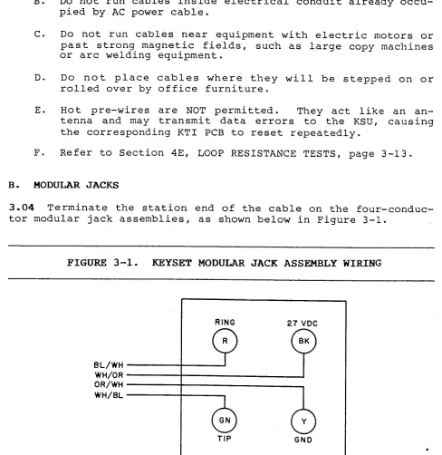
3.04 Terminate the station end of the cable on the four-conduc-
tor modular jack assemblies, as shown below in Figure 3-l.
FIGURE 3-l. KEYSET MODULAR JACK ASSEMBLY WIRING
BL/WH WH/OR OR/WH WH/BL
RING 27 VDC
Q p
TIP GND
INTER-TEL PRACTICES INSTALLATION
824 INSTALLATION h MAINTENANCE Issue 1, June 1984
4. ASSEMBLING THE MAIN DISTRIBUTION FRAME (MDF) BACKBOARD
4-01 The MDF is the point at which the KSU, the stations, and
the C.O. lines are connected to one another. It is. extremely
important that this be done accurately.
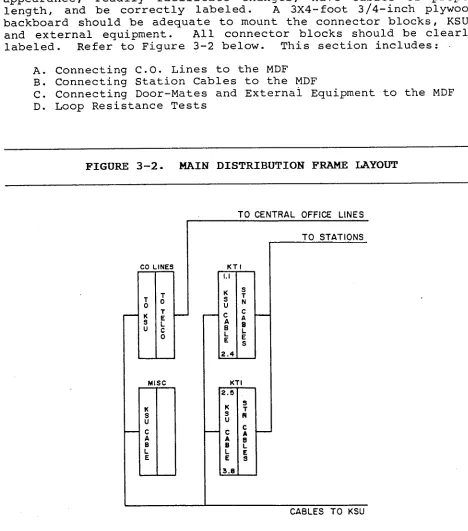
4.02 The MDF backboard should be constructed to present a neat
appearance, readily facilitate changes, have cables of proper
length, and be correctly labeled. A 3X4-foot 3/4-inch plywood
backboard should be adequate to mount the connector blocks, KSU,
and external equipment. All connector blocks should be clearly
labeled. Refer to Figure 3-2 below. This section includes:
A. Connecting C.O. Lines to the MDF
B. Connecting Station Cables to the MDF
C. Connecting Door-Mates and Externai Equipment to the MDF
D. Loop Resistance Tests
FIGURE 3-2. MAIN DISTRIBUTION FRAME LAYOUT
:0 -
x ; U
- NE: -
0’ I k 0 -
TO CENTRAL OFFICE LINES
I -
? N : L S -
TO STATIONS
CABLES TO KSU
NOTE : ALL BLOCK3 ARE 66M 150 TYPE
Page 3-5
INTER-TEL PRACTICES INSTALLATION
824 INSTALLATION & MAINTENANCE Issue 1. June 1984
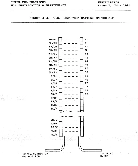
A. CONNECTING C-0. LINES TO THE MDF .:
4.03 Central Office (C.O.) lines are typically terminated on an
RJ-21X or RJ-14C connector. Then you terminate the lines on the
MDF. Refer to Figure 3-3 on the next page.
(1) One connection block on the MDF is dedicated for all C.O.
line connections. Terminate a 25-pair cable from the
right side of this block to the RJ-21X or RJ-14C. Label
both ends.
(2) Make an MDF PCB termination cable using 25-pair cable.
Use enough cable to reach from the KSU to the MDF:
a. Attach a 50-pin female amphenol connector to the KSU
end of the cable.
b. On the MDF end of the cable, terminate the wires on
the left side of the C.O. Lines block.
C. Use bridging clips to complete the connections.
d. Leave the PCB end of the cable hanging'until the KSU
is installed.
4.04 Lightning Protection: To ensure
tection,
adequate lightning pro-
install gas discharge tubes to ground on each C.O. line.
This must be done external to the system on the Central Office
side of the line. This protection should give energy absorption
and filter low-level surge potentials on the C.O. lines.
./ .
INTER-TEL PRACTICES INSTALLATION
824 INSTALLATION & MAINTENANCE Issue 1, June 1984
FIGURE 3-3. C-0. LIME TERMINATIONS ON TEIE MDF
WH/BL
BL/WH WH/OR
OR/WH
WH/GN
GN/WH
WH/BR
BR/WH
WH/SL
SL/WH
R/BL BL/R
R/OR
OR/R
R/GN
GN/R
R/BR
B R/R
R/SL
SL /R
TI
---- RI
---- T2
---- R2
---- T3
a--- R3
---- T4
---- R4
---- T5
---- R5
---- T6
---- R6
---- T7
---- R7
---- TB
---- RB
----
a---
----
---a
GN/V
V/BR
BR/V
V/SL
6
TO CO. CONNECTOR
ON MDF PCB
d
TO TELCO
RJ-21X
INTER-TEL PRACTICES INSTALLATION
824 INSTALLATION h MAINTENANCE Issue 1, June 1984
B. CONNEXTING STATION CABLES TO THE MDF
4.05 After station cables are run, they are connected to the MDF
as described below. Refer to Figure 3-4 and Figure 3-5 on the
following pages.
(1)
(2)
(3)
Ensure both ends of the cable are labeled with the cir-
cuit number.
Terminate each station cable on the right side of the
designated KTI block.
NOTE : Each KTI block supports up to 12 'stations.
Make an MDF PCB termination cable using 25-pair cable.
Use enough cable to reach from the KSU to the MDF:
a.
b.
C.
Attach a 50-pin female amphenol connector to the KSU
end of the cable.
On the MDF end of the cable, terminate the wires on
the left side of the KTI block.
DO NOT use bridging clips at this point. Leave the
PCB end of the cable hanging until the KSU is in-
stalled.
.
INTER-TEL PRACTICES INSTALLATION
824 INSTALLATION & MAINTENANCE Issue 1, June 1984
FIGURE 3-4. STATION CABLE TERMINATIONS
PART OF MOF
KTI BOARD
-
-iIs 1-I =I.1
- -
--
--
--
- ---
----
----
1
OR/WH ON07
OR/WI-l ON0
TO KEYSET
INTER-TEL PRACTICES INSTALLATION
824 INSTALLATION & MAINTENANCE Issue 1, June 1984
FIGURE 3-5. STATION CABLE TERMINATIONS ON THE KTI BLOCK
Terminal Number
26 WH - BL Tl TIP CKT 1 1.1 2.5
1 BL - WH Rl RING CKT 1
27 WH - OR +1 +3aV CKT 1
2 OR - WH Gl GROUND CKT 1
28 3 29 4
30
WH - GN T2
GN - WH R2
WH - BR +2
BR - h'H G2
TIP CKT 2 1.2 2.6
RING CKT 2 +3aV CKT 2 GROUND CKT 2
WH - SL T3 TIP CKT 3 1.3 2.7
SL - WH R3 RING CKT 3
R - BL +3 +3aV CKT'3
BL - R G3 GROUND CKT 3
3: 6
32 R - OR T4 TIP CKT 4 1.4 2.8
7 OR - R R4 RING CKT 4
33 R - GN +I +3aV CKT 4
a GN - R G4 GROUND CKT 4
34 R - BR T5 TIP CKT 5 1.5 3.1
9 BR - R R5 RING CKT 5
35 R - SL +5 +38V CKT 5
10 SL - R GS GROUND CKT 5
TIP CKT 6 1.6 3.2
RING CKT 6 +38V CKT 6 GROUND CKT 6
TIP CKT 7 1.7 3.3
RING CKT 7 +38V CKT 7 GROUND CKT 7
36 BK - BL T6
11 BL - BK R6
37 BK - OR +6
12 OR - BK G6
38 13 39 14 40 15 41 16 42 17 43 18 44 19 45 20 46 21 47 22 48 23 49 24
Cable Pair
Terminal Designation
BK - GN GN - Bti BK - BR BR - BK
BK - SL SL - BK
Y - BL
BL - Y
T7 R7 +7 G7 T8 R8 - +a Ga
Y - OR
OR - Y
Y - GN
GN - Y
T9 R9 4-9 G9
Y - BR TlO
BR - Y R10
Y - SL +10
SL - Y G10
V - BL Tll
BL - V Rll
V - OR +11
OR - V Gil
V - GN T12
GN - V R12
V - BR +12
BR - V G12
Function
Station
Circuit Number
TIP CKT 8 1.8 3.4
RING CXT a +3aV CKT a GROUND CKT 8
TIP CKT 9 2.1 3.5
RING CKT 9 .I
+3av cKT 9
GROUND CKT 9 I.. :
TIP CKT 10 2.2 3.6
RING CKT 10 +3SV CKT 10 GROUND CKT 10
TIP CKT 11 2.3 3.7
RING CKT 11 +3aV CKT 11 GROUND CKT 11
TIP CKT 12 2.4 3.8
RING CKT 12 _.
+3aV CKT 12 ,'
GROUND CKT 12
.
INTER-TEL PRACTICES INSTAJAATION
824 INSTALLATION & MAINTEiNANCE Issue 1, June 1984
1
c.
CONNECTING DOOR-MATES AND EXTERHAL EQUIPMEW'T TO THE MDF4.06 The MDF PCB has a Miscellaneous connector which provides
the interface from the KSU to the MDF for Door-Mates, the FAX
line monitor, external paging equipment, three remote contacts,
the Master-Tel connection, and the KSU frame ground. Refer to
SYSTEM SPECIFICATIONS for descriptions of these features.
4.07 To connect the equipment to the MDF, refer to Figure 3-6 on
the next page. Then proceed as follows:
(1) Terminate the equipment on the right side of the MISC
block.
(2) Make an interface cable to connect the MISC block to the
KSU. Use 25-pair cable long enough to reach.
a. Attach a female 25-pair amphenol connector to the KSU
end of the cable. Label both ends.
b. Connect the other end to the left side of the MISC
block.
I
C. Leave the MDF PCB end of the cable hanging until the
KSU is installed.
_ (3) Install bridging clips ,- ., for all connections except the
Door-Mates. 1,'
INTER-TEL PRACTICES INSTALLATION
824 INSTALLATION S MAINTENANCE Issue 1, June 1984
;i . .
FIGURE 3-6. MISCELLANEOUS TERMINATIONS ON THE MISC BLOCK
MDF
PART OF
MISC --- --- --- we- --- a-- --- ---
\iPU RTN 1 PAM ZONE 9 1 -J
--- --- ---
40 SK/SL
15 SL/BU
‘ll Y/ F11
--- -a- --- --- -a- --- --- --- --- --- --- --- --- --- --- MISC CONNECTOR ON THE MOF PC0
---- ---- -a-- ---- ---- ---- ---- ---- ---- ---- ---- ---- ---- ----
+&i-j MASTERTEL j 45 20 ,46 21 47 22 46 23 49 34
r
.INTER-TEL PRACTICES INSTALLATION
824 INSTALLATION & MAINTENANCE Issue 1, June 1984
D. LOOP RESISTANCE TESTS
4.08 Keysets must not exceed the loop limit of 800 feet or 40
ohms, using 24 AWG wire. The loop limit applies to any station,
even with a Power Failure Transfer keyset. Door-Mate units must
not exceed loop limits of 400 feet or 20 ohms.
4.09 Excessive and/or high resistance connections reduce the
cable lengths. Using larger gauge (smaller AWG number) or
multiple 24 AWG wires for the power pair increases these cable
lengths. Both pairs must maintain proper loops.
Station Loop Resistance Test
(1) Ensure bridging clips have not been installed at the MDF
and there are no keysets connected to the cables being
tested.
(2) Place a short across the RED and GREEN wires on the modu-
lar jack.
(3) On the- KTI block of the MDF, measure across the WHITE/-
BLUE BLUE/WHITE pair.
(4) This should read under 40 ohms. If it is higher, use
heavier gauge wire or double up by running another pair.
(5) Remove the short after the test is complete.
(6) Repeat this test for the other pair. Place a short
across the YELLOW and BLACK wires on the jack and measure
across the WHITE/ORANGE ORANGE/WHITE pair.
Door-Mate Loop Resistance Test
(1) Place a short across the two Door-Mate wires.
(2) Measure the Door-Mate's two wires on the MISC block of
the MDF.
(3) This should read under 20 ohms. If it is higher, use
heavier gauge wire or double up by running.another pair.
(4) Remove the short after the test is complete.