ISSN (Print) : 2320 – 3765 ISSN (Online): 2278 – 8875
I
nternational
J
ournal of
A
dvanced
R
esearch in
E
lectrical,
E
lectronics and
I
nstrumentation
E
ngineering
(An ISO 3297: 2007 Certified Organization)
Vol. 5, Issue 5, May 2016
Load Frequency Control Using Fuzzy Logic
Controller of a Three Area System Consisting
of a Grid Connected PV System, Hydro and
Thermal Systems
L.Jerline Beula1 , A.Josephine Amala2
PG Student [PSE],Dept. of EEE, JJ College of Engineering &Technology, Trichy, Tamilnadu, India1 HOD, Dept. of EEE, JJ College of Engineering &Technology, Trichy, Tamilnadu, India2
ABSTRACT: In this paper the load frequency control of the three area system consisting of thermal, hydro and photovoltaic system. Using modified hill climbing algorithm, the maximum power point tracking is performed in photovoltaic. Combining fuzzy logic with hill climbing algorithm the modified hill climbing is performed. Boost converter is used for this analysis. Using single phase inverter the obtained DC output is converted to AC output. By using sinusoidal pulse width modulation the Grid connection is performed. Transfer function model of the thermal , hydro is interfaced with the photovoltaic system. Load frequency control of this three area system and simulation of the entire system is performed in the MATLAB SIMULINK.
KEYWORDS: PhotoVoltaic (PV), Maximum Power Point Tracking (MPPT), Hill Climbing, Load Frequency
Control (LFC), Area Controlled Error (ACE), Sinusoidal Pulse Width Modulation (SPWM)
I. INTRODUCTION
Renewable energy is the energy given by the natural resources like sunlight, wind, tides, geothermal heat etc. These resources are endless resources as compared to the other conventional fossil fuels. So now a days, the world is promoting to use the renewable energy sources. Clean Development Mechanisms(CDMs) are being adopted by organizations all across the globe[1]. It is possible to reduce the pollution rate into a significant level by using the renewable energy sources. The cost of production of conventional energy sources is increasing per day. So the solar energy is getting a suitable replacement for it. These solar energy is pollution less, spreads all over the earth and abundant. Parallel and series combination of PV cells are called as PV arrays. By using the solar isolation and temperature the PV cells are generating the electrical energy. Active or passive are the main two classifications for the solar technologies. Depending upon the changeover, the way they catch and distribute sunlight Active solar proficiencies use photovoltaic arrays, pumps and fans to convert sunlight into executable outputs. It is convert to the electrical energy the most useful form of energy. Using the solar photovoltaic cell this is achieved. About 13%-17% is the efficiency of solar photovoltaic cells with single crystal silicon[1], [3] In a grid connected system during the day time the major part of the load is supplied by the PV array and when the sunlight is not sufficient then the power to the load is taken from the grid [2], [3].
II. GRID CONNECTED SOLAR SYSTEM
ISSN (Print) : 2320 – 3765 ISSN (Online): 2278 – 8875
I
nternational
J
ournal of
A
dvanced
R
esearch in
E
lectrical,
E
lectronics and
I
nstrumentation
E
ngineering
(An ISO 3297: 2007 Certified Organization)
Vol. 5, Issue 5, May 2016
Fig. 1. Block Diagram of PV System
In fig 1 DC output voltage have to convert to AC voltage in order to perform the grid connection. So the single phase inverter is here use to convert the DC output voltage to AC voltage. In order to perform the grid connection SPWM technique is also used.
A. SOLAR CELL PANEL
Solar cell panel works on the principle of photo voltaic effect. A solar cell consists of a semiconductor where the front and reverse side have been processed. So that the front side normally has a surplus of free electrons while the reverse side has a deficit [3]. Bound electrons in the solar cell can absorb a photon and thereby become mobile. Thus the absorbed photon caught by the field in the interface and transported to the front side of the cells [3]. If the front-and reverse side are connected with an electrical circuit, the electron can do useful work in a light bulb, electrical motor and computer. Solar cells give an output voltage of approximately 0.3-0.6V depending on the technology [3],[4].
Fig. 2. Equivalent circuit of solar cell
In fig 2 equivalent circuit of a solar cell is as shown in the figure 2. Solar panel can be modeled with the help of equation,
Where,
I0 = Solar cell output current , I = Dark saturation current, I1 = Photo current, Isc = Short circuit current v = Solar cell output voltage, k = Boltzmann constant, q = Charge of electron, A = Diode quality factor
T = Temperature in Kelvin, Λ = Irradiance
Depending up on the temperature and the irradiance, power is generated [3],[4]. It is directly proportional to the irradiance and inversely proportional to temperature. This can be shown in figure 3,4.
B. MAXIMUM POWER POINT TRACKING
ISSN (Print) : 2320 – 3765 ISSN (Online): 2278 – 8875
I
nternational
J
ournal of
A
dvanced
R
esearch in
E
lectrical,
E
lectronics and
I
nstrumentation
E
ngineering
(An ISO 3297: 2007 Certified Organization)
Vol. 5, Issue 5, May 2016
According to maximum power transfer theorem,the power output of a circuit is maximum when the Thevenin impedance of the circuit (source impedance) matches with the load impedance.[4][5] Hence our problem of tracking the maximum power point reduces to an impedance matching problem.
Fig.3.Temperature and irradiance effect on P-V characteristics
By varying the duty cycle of the DC match the source impedance with load impedance is based on the Power versus Voltage characteristic of a solar panel shown in Fig. 3. The point on the curve where the power is maximized is called the Maximum Power Point (MPP) of the solar panel.
Fig. 4 Temperature and irradiance effect on I-V characteristics
load. Another advantage of this technique is that, if an up/down converter is used for the maximum power point tracker; power can then be delivered to loads with higher or lower voltage than the solar panel, enabling new applications for the same solar panel. Here in this method fuzzy logic control is combined with the hill climbing method to eliminate the disadvantage of both the method. Fuzzy logic controller will take care of the dynamic characteristic[4],[5],[10] of the PV panel while hill climbing algorithm will take care of the static characteristic of the PV panel will take care by the hill climbing algorithm method.
Hill climbing algorithm used in constant weather conditions while the fuzzy logic controller will be used in the changing weather condition. This method improves the tracking speed as compared to when fuzzy logic and hill climbing methods are used alone separately.
III. FUZZY LOGIC CONTROLLER
In this proposed method change in power and change in current are taken as the input to the fuzzy logic controller while change in duty cycle is taken as the output of the fuzzy logic controller. The output thus obtained is given as the firing pulse of the boost converter and the boost converter will regulate the voltage.
Where,
∆P = Change in power
∆I = Change in current
ISSN (Print) : 2320 – 3765 ISSN (Online): 2278 – 8875
I
nternational
J
ournal of
A
dvanced
R
esearch in
E
lectrical,
E
lectronics and
I
nstrumentation
E
ngineering
(An ISO 3297: 2007 Certified Organization)
Vol. 5, Issue 5, May 2016
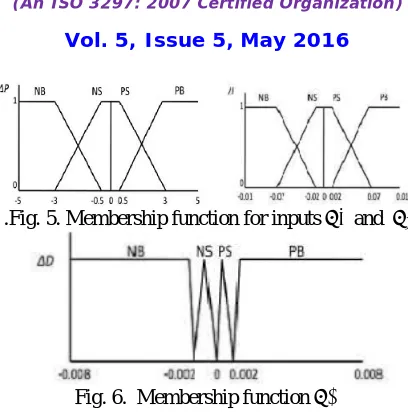
.Fig. 5. Membership function for inputs ∆P and ∆I
Fig. 6. Membership function ∆D
Inputs change in power and current and the output change in duty cycle are divided into four fuzzy subsets. Namely, negative big(NB), negative small(NS), positive small(PS), positive big(PB). Mamdani’s method with Max-Min is used for the Fuzzy combination [4],[5]. Defuzzification is the last stage of fuzzy controller. Center of Area Algorithm is used here for Defuzzification
Table 1. fuzzy rule base
Overall system of an grid connected PV system, hydro and thermal system is connected together and shown by fig 7
Fig 7 overall system
IV. LFC OF THREE AREA SYSTEM CONSISTS OF THERMAL, HYDRO AND PV SYSTEM
Changes in the power system load, affect mainly the system frequency and real power. [8] Mainly deals with the control of the system frequency and real power. Load frequency control is the basis of many advanced concepts of the large scale control of the power system. The reasons for keeping a strict limit on the system frequency variation were • The speed of the alternating current motors depends on the frequency of the power supply.
• If the normal frequency is 50 Hertz and the system frequency falls below 47.5 Hertz or goes up above 52.5 Hertz then the blades of the turbine are likely to get damaged so as to prevent the stalling of the generator
• The under frequency operation of the power transformer is not desirable.
ISSN (Print) : 2320 – 3765 ISSN (Online): 2278 – 8875
I
nternational
J
ournal of
A
dvanced
R
esearch in
E
lectrical,
E
lectronics and
I
nstrumentation
E
ngineering
(An ISO 3297: 2007 Certified Organization)
Vol. 5, Issue 5, May 2016
A. PV PANEL MODEL
In three area system model we have to create the transfer function model of the each system.[6][7] PV system consists of the PV panel, MPPT, Inverter, Filter. Transfer function model of the each unit has to find out and to create a single transfer function model. The transfer function model of the PV panel can be find out from the equation 1 and 2.
B. THERMAL
The main parts in the thermal generator are Generator, Turbine , Governor , Reheater. We have to consider the transfer function model of the each unit to form the model. [6][7].
Fig 8 Thermal generator model
C. HYDRO
Hydro plants are modelled the same way as thermal plants. The input to the hydro turbine is water instead of steam. Initial droop characteristics owing to reduced pressure on turbine on opening the gate valve has to be compensated.
Fig 9. Hydro generator model
Fig 9, Hydro turbines have peculiar response due to water inertia; a change in gate position produces an initial turbine power change which is opposite to that sought. For stable control performance, a large transient (temporary) droop with a long resettling time is therefore required in the forms of transient droop compensation.
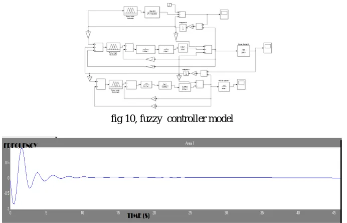
fig 10, fuzzy controller model
ISSN (Print) : 2320 – 3765 ISSN (Online): 2278 – 8875
I
nternational
J
ournal of
A
dvanced
R
esearch in
E
lectrical,
E
lectronics and
I
nstrumentation
E
ngineering
(An ISO 3297: 2007 Certified Organization)
Vol. 5, Issue 5, May 2016
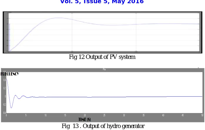
Fig 12 Output of PV system
Fig 13 . Output of hydro generator
V. CONCLUSION
Maximum power point tracking was done for the PV system using fuzzy logic controller and then grid connection was performed using SPWM technique. Transfer function model of this system was taken and interfaced with thermal generator and hydro generators. Outputs are simulated by MATLAB .
REFERENCES
[1]. P.Fairley, "Fukushima's positive impact [SpectralLines],"Spectrum, IEEE, vol. 48, no. 5, p. 8, May 2011
[2]. G.Spagnuolo, "Renewable energy operation and conversion schemes," IEEE Ind. Electron. Mag. , vol. 4, no. 1, pp. 38-51,Mar. 2010.
[3]. D. Sonnenenergie, "Photovoltaic Basics, in Planning and installing photovoltaic systems: A guide forinstallers,architects,and engineers”, 2nd ed., Deutsche Gesellschaft für Sonnenenergie, Ed. London: EarthscanPublications Ltd., 2008, ch. 1, pp. 1-62
[4] Bader N. Alajmi, Khaled H. Ahmed, Stephen J. Finney, and Barry W. Williams “Fuzzy-Logic-Control Approach of a Modified Hill-Climbing Method for Maximum Power Point in Microgrid Standalone Photovoltaic System” IEEE TRANSACTIONS ON POWER ELECTRONICS, VOL. 26, NO. 4, APRIL 2011
[5] A. Al Nabulsi, R. Dhaouadi,”Fuzzy Logic Controller Based Perturb and Observe Maximum Power Point Tracking”, International Conference on Renewable Energies and Power Quality (ICREPQ’12) Santiago de Compostela (Spain), 28th to 30th March, 2012
[6] Seyed Ali Jeddi,Seyed Hamidreza Abbasi,Fereydoon Shabaninia, “ Load Frequency Control of Two Area Interconnected Power System (Thermal Generator and Solar PV) with PI and FGSPI Controller” The 16th CSI International Symposium on Artificial Intelligence and Signal Processing (AISP 2012)
[7] Manoj Dattaa, Tomonobu Senjyu, Atsushi Yona and Toshihisa Funabashi, “A fuzzy based method for leveling output power fluctuations of photovoltaic-thermal hybrid power system” Renewable Energy Volume 36, Issue 6, June 2011, Pages 1693- 1703