ISSN (Print) : 2320 – 3765 ISSN (Online): 2278 – 8875
I
nternational
J
ournal of
A
dvanced
R
esearch in
E
lectrical,
E
lectronics and
I
nstrumentation
E
ngineering
(A High Impact Factor, Monthly, Peer Reviewed Journal)
Website: www.ijareeie.com
Vol. 7, Issue 8, August 2018
Performance Analysis of a Single Neuron
based Adaptive Controller and PI Controller
based PMBLDC Motor Drive
Md. Belal Hossen1, Bashudeb Chandra Ghosh2
M.Sc. Engineering student, Dept. of EEE, Khulna University of Engineering &Technology, Khulna, Bangladesh1
Professor, Dept. of EEE, Khulna University of Engineering &Technology, Khulna, Bangladesh2
ABSTRCT: This paper proposes single neuron based controller with adaptation law and conventional PI controller for the Permanent Magnet Brushless Direct Current (PMBLDC) motor drives. The controllers control the motor speed as output variable but inherently it adjusts all the required variables to achieve the field-orientation aspect. It is difficult to handle the dynamics of the motor by using conventional PI controller due to changes in motor ratings and characteristics and tuning is necessary to achieve desired performance. In order to overcome this problem, the more versatile single neuron based adaptive controller is proposed and developed. The PI controller is designed and tuned by Ziegler-Nichols method. The performance of drive system is studied for starting condition, speed variation, sudden load torque change and by changing parameters of the motor in C++ simulation. The simulation results are compared between the single neuron based adaptive controller and traditional PI Controller.
KEYWORDS: PMBLDC motor, PI Control, SN based adaptive control, FOC and Trapezoidal back emf.
I. INTRODUCTION
ISSN (Print) : 2320 – 3765 ISSN (Online): 2278 – 8875
I
nternational
J
ournal of
A
dvanced
R
esearch in
E
lectrical,
E
lectronics and
I
nstrumentation
E
ngineering
(A High Impact Factor, Monthly, Peer Reviewed Journal)
Website: www.ijareeie.com
Vol. 7, Issue 8, August 2018
reference speed with and without load disturbances in closed loop control but the demerit of conventional PID can be observed in its steep overshoot in the closed loop transient response. For the field oriented vector control, the direct axis current Idr and quadrature axis current Iqr are controlled to generate the required torque. In the field oriented control;
where three phase stator current are identified as two orthogonal 'dq' component; Idr and Iqr are responsible for field
component and torque component. Field flux and armature flux linkage are created by field current and armature current and these are aligned orthogonally. When torque is controlled, field flux is not affected. As only the quadrature axis current produces useful torque and the direct axis current has no effect on torque production. So direct axis current Idr of PMBLDC motor is considered zero to get maximum torque efficiency[7]. Modelling and performance analysis of
PID controlled BLDC motor and different schemes of PWM controlled BLDC motor is presented [8]. Nowadays, classic control is the most used for controlling of any application system. But it is well known that users need to know the system’s characteristics to reach optimal control. The proportional integral derivative controller is designed based on single artificial neural network with aim to improve its performance [9]. The single neuron PID control strategy which combine the advantage of conventional PID control with adaptability of artificial neuron control. They applied the controller in an aircraft deicing fluids rapid heating system. The simulation results showed that the single neuron PID control strategy perform effectively on the temperature turbulence problem of aircraft deicing fluids rapid heating system. Experiments are conducted to verify the single neuron PID control strategy, the results of which show that the single neurons PID control strategy can achieve the request in practical application of the aircraft deicing fluids rapid heating system [10].
In paper [11] a single artificial neural network algorithm control of PMBLDC motor is presented. This paper proposes single neuron based adaptive control with adaptation law and conventional PI controller for PMBLDC motor. Both controller control motor speed for their desire speed .But it is difficult to handle the dynamics of the motor by using conventional PI controller due to changes in motor ratings and characteristics and tuning is necessary to achieve desired performance. In order to overcome this problem, the single neuron based adaptive controller is proposed and developed. The PI controller is designed and tuned by Ziegler-Nichols method. The performance of drive system is studied for starting condition, speed control, load torque variation and by changing parameters of the motor in C++ simulation.
II. MATHEMATICAL MODEL OF THE MACHINE
Permanent magnet Brushless DC (PMBLDC) motor consists of three stator windings connected in star fashion and a rotor. The rotor is made of permanent magnet and can vary from two to eight pole pairs with alternate north and south poles. Ferrite materials are used for permanent magnets. Recently PMBLDC motor use rare earth magnetic materials such as NdFeB for their field construction. The mechanical commutator and brushes are replaced by electronic circuits. So PMBLDC motor is constructed with a permanent magnet rotor and wire wound stator poles [3] and [12].The flux distribution in BLDC motor is trapezoidal and therefore the d-q axes rotor reference frame model is not applicable. For this non-sinusoidal flux distribution, it is suitable to drive a model of PMBLDC motor on the basis of phase variables. The permanent magnet creates trapezoidal field. Therefore the back EMF's are also trapezoidal as given in (1).
ea
eb
ec
= ωmλm
fas(θr)
fbs(θr)
fcs(θr)
(1)
Where, m is the flux linkage, m is angular rotor speed in radian per second, r is the rotor position in radian and
Classical modeling equations are used to model the PMBLDC motor and hence the motor model is highly flexible. These equations are based on the dynamic equivalent circuit of PMBLDC motor. Resistance of all the phase windings is assumed to be equal to . By considering ideal non-salient rotor with uniform reluctance reduces the three phase voltage equation to the form as shown in Eq. 2.
Vas
Vbs
Vcs
=
Rs 0 0
0 Rs 0
0 0 Rs
ia
ib
ic
+ dtd
L M M M L M M M L
ISSN (Print) : 2320 – 3765 ISSN (Online): 2278 – 8875
I
nternational
J
ournal of
A
dvanced
R
esearch in
E
lectrical,
E
lectronics and
I
nstrumentation
E
ngineering
(A High Impact Factor, Monthly, Peer Reviewed Journal)
Website: www.ijareeie.com
Vol. 7, Issue 8, August 2018
Where, , , are the phase voltages of stator winding, , , are the stator phase currents, is the stator resistance per phase, = = = are self-inductance of phase a, b, c respectively, = = = are mutual inductance between phases. The phase currents of stator are considered to be balanced for no neutral connection. With no neutral connection ia+ib+ ic=0 the system equations are modified. Then following equations are used to simplify
inductances matrix and to describe the system in state space form as
̇
= + + (3) Where, x=[ia ib ic]t (4)
u=[V as Vbs Vcs]
t
(5) e=[ea eb ec]t (6)
A = ⎣ ⎢ ⎢ ⎢ ⎡ -Rs
L-M 0 0
0 - Rs
L-M 0
0 0 -L-MRs⎦⎥
⎥ ⎥ ⎤ (7) B = ⎣ ⎢ ⎢ ⎢ ⎡ 1
L-M 0 0
0 L-M1 0 0 0 1
L-M⎦ ⎥ ⎥ ⎥ ⎤ (8) C = ⎣ ⎢ ⎢ ⎢ ⎡ -1
L-M 0 0
0 -L-M1 0 0 0 - 1
L-M⎦ ⎥ ⎥ ⎥ ⎤ (9)
The system consists of two other mechanical variables as described now. The electromagnetic torque developed is given by
Te=[eaIa+ebIb+ecIc]/ωm (10)
If the system moment of inertia , friction coefficient B is constant and load torque is l, then the system motion
equation is
Jdωm
dt + B ωm= (Te-Tl) (11)
Where, = m + Jl. m and l are the moment of inertia of motor and load respectively. Electrical rotor speed and
position is related by this equation. Here, is number of poles. The rotor position r repeats every 2π radians.
dθr
dt = P
2ωm (12)
III. CONTROLLER DESIGN
A. CONVENTIONAL PI SPEED CONTROLLER OF BLDC MOTOR
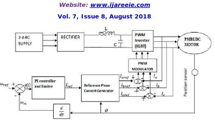
This drive system consists of PI speed controller with current limiter, the reference current generator, PWM current controlled , position sensor and IGBT based current controlled voltage source inverter (CC-VSI).The basic block diagram of PMBLDC drive is showed with PI Speed controller in fig.1
ISSN (Print) : 2320 – 3765 ISSN (Online): 2278 – 8875
I
nternational
J
ournal of
A
dvanced
R
esearch in
E
lectrical,
E
lectronics and
I
nstrumentation
E
ngineering
(A High Impact Factor, Monthly, Peer Reviewed Journal)
Website: www.ijareeie.com
Vol. 7, Issue 8, August 2018
Fig 1The basic block diagram of PMBLDC drive is showed with PI Speed controller
The position sensor is used to obtain the rotor position information and the drive system has an outer speed loop and an inner current loop for speed and current control. Three separate current sensors are used to measure the phase current as well as a proportional –Integral (PI) is included into PI speed control block which attempts to correct the error between a measured process variable and desired set point by calculating and then outputting a corrective action that can adjust the process accordingly. The proportional mode determine the reaction to the current error, integral mode determines the reaction based recent error. This controller is widely used in the industry due to its ease in design and simple structure. The PI controller algorithm can be implemented as
Output (t)=kpe(t)+kI∫ e(τ) t
0 dτ (13)
Actual Speed is compared with reference speed and resultant error is processed in PI controller.
Error e(t)=ωmref-ωm, Where the gains of and are proportional and Integral. The resulting error is calculated at nth
sampling rate as, Iref(t)= Iref t-1 +kp[e(t)- e t-1 ] + kIe(t) (14)
The output of this controller is considered as a reference torque component current. A limit is put on the speed controller output depending on permissible maximum winding currents.
Depending on the rotor position, The reference current generator generate three phase reference currents (Iaref, Ibref,Icref)
which is equal to magnitude of .The actual phase currents are compared with reference phase currents and the error is given to PWM current controller to produce the switching signals for the inverter switches. The rotor position and reference current are shown in Tabile1 [13].
ISSN (Print) : 2320 – 3765 ISSN (Online): 2278 – 8875
I
nternational
J
ournal of
A
dvanced
R
esearch in
E
lectrical,
E
lectronics and
I
nstrumentation
E
ngineering
(A High Impact Factor, Monthly, Peer Reviewed Journal)
Website: www.ijareeie.com
Vol. 7, Issue 8, August 2018
The model of PMBLDC motor is designed based on electrical components and mechanical elements. Commonly, the 3-phase motor has better efficiency, cost implications, good precision control and gives quite low torque [14]. For symmetrical arrangement, mechanical and electrical time constant equations are written by
τm=∑ RJ KeKt=
J∑R
KeKt (15)
τe=∑ L R=
L
∑R (16)
Where R and L are resistance and inductance per phase, and are back emf and torque constant, J is rotor inertia. Therefore, the transfer function of the PMBLDC motor is
G(s)=
1 Ke
τmτe.s2+τm.s+1 (17)
Using the Ziegler and Nichols technique the controller constants are evaluated as [15] kp=2.7; ki=16..2
B. SINGLE NEURON BASED ADAPTIVE CONTROLLER WITH GAIN ADJUSTMENT
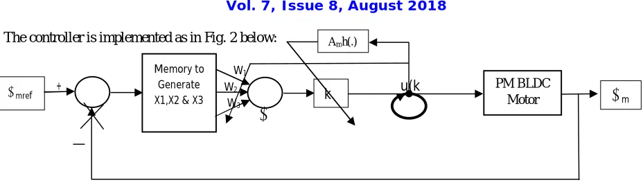
In fact, single neuron controller is an adaptive control algorithm similar to the variations of the coefficients of proportion, integral, differential. It is a feed-forward neural network [9, 10, 11].Here, w1, w2 and w3 are the weights
and x1(k), x2(k) and x3(k) are the inputs to the system. Their values are given below:
x2(k)=ωmref-ωm=ωmerror=e(k) (18)
x1(k)=e(k)-e(k-1) (19)
x3(k)=e(k)-2e k-1 -e(k-2) (20)
The output of the controller is the input to the system u (k) written as:
u(k)=u k-1 +kk∑3i=1wi(k)xi(k) (21)
For neuron output a nonlinear activation function was selected as kk=Amax 1-e-u(K) 1+e-u(k) (22)
Where, the factor kk is adjusted to get the desired response. It is very important to select the value of kk. The larger is the kk value, the better is the rapidity, but the overshoot is big and it may even make the system unstable. When the charged object delay increases, kk value must be reduced in order to ensure the stability of the system. The maximum value of kk is 0.964 and value of is 4.0. Identification-free adaptive control algorithm proposed by Marisk and Strejec can be used for online adjustment of kk value.
The weights virtually corresponds to the PID controller constants and are updated using the following rule
Wi(k)=Wi k-1 +ɳixix2u(k) (23)
Normalized weights are used in (21) as below:
wi(k)= Wi(k)
ISSN (Print) : 2320 – 3765 ISSN (Online): 2278 – 8875
I
nternational
J
ournal of
A
dvanced
R
esearch in
E
lectrical,
E
lectronics and
I
nstrumentation
E
ngineering
(A High Impact Factor, Monthly, Peer Reviewed Journal)
Website: www.ijareeie.com
Vol. 7, Issue 8, August 2018
The controller is implemented as in Fig. 2 below:
Fig 2 SN based controller implementation with weight update feature
IV. RESULTS AND DISCUSSION
The system simulation is done by C++ program code used Code Block software running this simulation and plots are taken by Origin software using the generated data file from C++ program simulation. Parameters of this motor are considered as follows: resistance Rs=0.36Ω; self-inductance Ls=2.1mh; mutual inductance Lm=1.5mh; flux linkage
constant or = 0.105V.S/radian, torque constant =0.36Nm/A; moment of inertia=0.0048 ; damping constant=0.002Nm/radian/s, poles=4.0; rated voltage =48V, rated current =4A; load torque = 0.9 Nm and rated speed =150 radian/sec. Simulation parameters for single neuron adaptive controller are follows as:w1(k)=10.025;w2(k)=10.0001;w3(k)=110.001;ηp=1.4;ηI=10.6;ηD=5.12.
A. STARTING CONDITION
For constant PI and SN adaptive controller, the motor was started from rest condition with speed 150 radian per sec and load torque 0.9 Nm. In this case speed response is shown in fig.3 (a) for the both controllers and it is evident that speed response of both controllers are overlapped one another in all time. We observed that both controllers work effectively for fast controlling speed and there is no overshoot or undershoot in all the speed responses. Qudrature axis current level is plotted in fig.3 (b) for conventional PI and SN adaptive controller. It is clear that Iqr current levels of both
controllers are identical with overlapping one another in all time. At starting, motor draws maximum constant current before reaching desire speed and when motor reaches to desire speed, Iqr current varies from 4A to 0A and 0A to 4A
limit. As both controllers change their speed synchronously, Iqr current will be changed with their speed variation. For
both controllers, back emfs variation with speed are given in fig.3(c) and 3(d) and it is visual that initial back emfs are zero because initial motor speed is zero. Back emfs will be increased with increment of speed. When the motor reaches to set speed the motor speed remains constant and the back emfs also remain constant. In the stator winding induced emfs of PMBLDC motor will be trapezoidal pattern due to its trapezoidal field pattern and it is shown in fig.4 (a) and fig.4 (b) for PI and SNA controller. Variation of rotor position with during starting is given for PI and SNA controller in fig.4(c) and fig.4(d).Rotor angle varies from 0.0 to 6.28 radian and as the initial speed is very low it takes more time
to reach 2π radians. These characteristics also indicate the effectiveness of both the controllers.
u(k
_ +
W3
W1
W2 PM BLDC
Motor Memory to
Generate
X1,X2 & X3 ωm
ωmref k
Amh(.)
∑ lƩ
ISSN (Print) : 2320 – 3765 ISSN (Online): 2278 – 8875
I
nternational
J
ournal of
A
dvanced
R
esearch in
E
lectrical,
E
lectronics and
I
nstrumentation
E
ngineering
(A High Impact Factor, Monthly, Peer Reviewed Journal)
Website: www.ijareeie.com
Vol. 7, Issue 8, August 2018
Fig.3 (a) Speed response with PI and SNA control Fig.3 (b) Q axis current levels of PI and SNA control
Fig.3 (c) Back emfs variation with PI control Fig.3 (d) Back emfs variation with SN adaptive control
ISSN (Print) : 2320 – 3765 ISSN (Online): 2278 – 8875
I
nternational
J
ournal of
A
dvanced
R
esearch in
E
lectrical,
E
lectronics and
I
nstrumentation
E
ngineering
(A High Impact Factor, Monthly, Peer Reviewed Journal)
Website: www.ijareeie.com
Vol. 7, Issue 8, August 2018
Fig.4(c) Rotor angle variation for PI control Fig.4 (d) Rotor angle variation for SN adaptive control
B. SPEED VARIATION
Speed variation of drive system is frequently needed. For conventional PI and SN based Adaptive controller, we consider initial reference speed 150 radian per sec and load torque 0.9Nm. After 0.7 sec speed was reduced from 150 rad/sec to 75 rad/sec and after 1.4 sec speed was increased to 150 rad/sec as shown in fig. 5(a) for both controllers. It is noticed that actual speed of both controllers reaches to the changeable reference speed in same time. Due to speed variation and acceleration, q axis current is required. For higher or lower speed, more or less torque is required to overcome friction component. As speed related with torque which is directly proportional to Iqr. Iqr currents will be
control with speed variation and it is given in fig. 5(b) for these controllers. It is observed that Iqr is higher and lower
with higher and lower speed but there is very less oscillation for SNA control. So we can say that Iqr is smoothly
controlled by SNA control but Iqr is not controlled by PI, because Iqr remains constant all desire speed. Back emfs of
both controllers are similar because actual speed of both controllers reaches to reference speed in same time.3 phase back emfs are plotted in fig. 5(c) and 5(d) for PI and SNA controller. Rotor angle variation increases with increment of speed. Rotor angle variation of PI and SNA controller are shown in fig.6 (a) and 6(b).
ISSN (Print) : 2320 – 3765 ISSN (Online): 2278 – 8875
I
nternational
J
ournal of
A
dvanced
R
esearch in
E
lectrical,
E
lectronics and
I
nstrumentation
E
ngineering
(A High Impact Factor, Monthly, Peer Reviewed Journal)
Website: www.ijareeie.com
Vol. 7, Issue 8, August 2018
Fig.5 (c) 3 phase back emf variation for PI control Fig.5 (d) 3 phase back emf variation for SN adaptive control
Fig.6 (a) Rotor angle variation with PI control Fig.6 (b) Rotor angle variation with SNA control
ISSN (Print) : 2320 – 3765 ISSN (Online): 2278 – 8875
I
nternational
J
ournal of
A
dvanced
R
esearch in
E
lectrical,
E
lectronics and
I
nstrumentation
E
ngineering
(A High Impact Factor, Monthly, Peer Reviewed Journal)
Website: www.ijareeie.com
Vol. 7, Issue 8, August 2018
Fig.7 (a) 3 phase currents with PI control Fig.7 (b) 3 phase currents with SNA control
C. SUDDEN LOAD TORQUE CHANGE
For constant PI and single neuron based adaptive controller, we consider initially load toque 0.9Nm while motor was operating at 150rad/sec speed and after 1.0 second load torque was increased to 1.8Nm as shown in fig.8 (a).When load torque increases, q axis current level varies in this range from 1.75A to 4 A as shown in figures 8(b) and 8(c) for constant PI and SNA control. It is noticed that qudrature axis current level of adaptive single neuron was changed smoothly but there was some oscillations in the PI control. But there is no effect on speed for SNA control system. In this case speed response is shown in fig.8 (d). For this controller, back emfs and rotor angle variation are remain constant due to remain constant speed, because no effect of motor speed on load torque change. Back emf and rotor angle variation are given in fig.9 (a) and fig.9 (b).
ISSN (Print) : 2320 – 3765 ISSN (Online): 2278 – 8875
I
nternational
J
ournal of
A
dvanced
R
esearch in
E
lectrical,
E
lectronics and
I
nstrumentation
E
ngineering
(A High Impact Factor, Monthly, Peer Reviewed Journal)
Website: www.ijareeie.com
Vol. 7, Issue 8, August 2018
Fig.8 (c) Qudrature axis current varies by SNA control Fig.8 (d) Speed response for SN adaptive control
Fig.9 (a) 3 phase back emf variation with SNA control Fig.9 (b) Rotor angle variation for SNA control
D. BY CHANGING PARAMETER
For Single neuron based adaptive controller, the motor is started with speed 150 radian per sec and load torque 0.9Nm. After 1 see, the stator resistance of this motor was increased by 1.5 time of rated value. In this case it is observed that speed response, qudrature axis current level, rotor angle variation are not affected on changing motor parameter. For this case stator resistance, speed response, qudrature axis current and rotor angle variation are shown as the following figures 10 (a), 10 (b), 10(c) and 10(d) respectively. For fixed PI control system, motor does not work effectively due to change its parameter. In this case, values of kp and Ki are needed to be adjust. The motor also runs under stable
ISSN (Print) : 2320 – 3765 ISSN (Online): 2278 – 8875
I
nternational
J
ournal of
A
dvanced
R
esearch in
E
lectrical,
E
lectronics and
I
nstrumentation
E
ngineering
(A High Impact Factor, Monthly, Peer Reviewed Journal)
Website: www.ijareeie.com
Vol. 7, Issue 8, August 2018
Fig.10 (a) Stator resistance changes at 1 sec Fig.10 (b) Speed response for SN adaptive control
Fig.10 (c) Qudrature axis current changes by SNA Fig.10 (d) Rotor angle variation by SNA control
V. CONCLUSION
In this paper, we have presented a new approach for controlling of PMBLDC motor drive. The simulation results are compared between single neuron based adaptive controller and conventional PI controller. We have observed from the simulation results that the PMBLDC motor can be controlled effectively using single neuron. The drive system is stable and the single neuron based adaptive control can be applied to the drive systems with replacement of motor having unknown parameters. It is also observed that the drive system develops the required amount load torque needed without any speed change.
REFERNCES
[1] Hrushikesh Meher, “Performance Analysis of Interior Permanent Magnet Synchronous Motor (IPMSM) Drive System using different Speed Controllers,” M Tech Thesis, Department of Electrical Engineering National Institute of Technology Rourkela, India.
[2] R. Giridhar Balakrishna, P. Yogananda Reddy, “Speed Control of Brushless DC Motor Using Microcontroller,” International Journal of Engineering Technology, Management and Applied Sciences, vol. 3, Issue 6, ISSN 2349-4476, June 2015.
ISSN (Print) : 2320 – 3765 ISSN (Online): 2278 – 8875
I
nternational
J
ournal of
A
dvanced
R
esearch in
E
lectrical,
E
lectronics and
I
nstrumentation
E
ngineering
(A High Impact Factor, Monthly, Peer Reviewed Journal)
Website: www.ijareeie.com
Vol. 7, Issue 8, August 2018
[4] Tony Mathew and Caroline Ann Sam, “Modeling and closed loop control of BLDC motor Using a single current sensor,” International Journal of Advance Research in Electrical, Electronics and Instrumentation Engineering, vol. 2, Issue 6, pp. 2525-2530, June 2013.
[5] Purna Chandra Rao, Y. P. Obulesh and Ch. Sai Babu,“ Mathematical Modelling of BLDC Motor with Closed Loop Speed Control using PID Controller under various Loading Conditions ,” ARPN Journal of Engineering and Applied Sciences, 2006-2012 Asian Research Publishing Network (ARPN). All rights reserved, ISSN 1819-6608 ,VOL. 7, NO. 10, Oct 2012.
[6] Brajesh Kumar, Subrat Kumar Swain and Dr. Nirbhar Neogi, “Controller Design for Closed Loop Speed Control of BLDC Motor ,” International Journal on Electrical Engineering and Informatics - Volume 9, Number 1, March 2017.
[7] Protik Chandra Biswas, Bashudeb Chandra Ghosh and Md. Ashraful Islam, “Field Oriented Control of a Current Fed PMBLDC Motor and Its Comparison to Scalar Control Drive,” The AIUB Journal of Science and Engineering (AJSE), vol. 15, no. 1, August 2016.
[8] Vinod KR Singh Patel and A.K. Pandey, “Modeling and Performance Analysis of PID Controlled BLDC Motor and Different Schemes of PWM Controlled BLDC Motor, ” The International Journal of Scientific and Research Publication, Vol.3,Issue 4,ISSN 2250-3153,April 2013. [9] J.Rivera Mejia, A J Leon-Rubio, E Arzabaia-Contreras, ”PID based on a Single Artificial Neural Network Algorithm for Intelligent Sensors,”
Journal of Applied Research and Technology, April 2012, pp.262-282.
[10] Bin Chen, Hong-zhen Yang, Li-wen Wang,” Single Neuron PID Control of Aircraft Deicing Fluids Rapid Heating System,” Journal of Networks, Vol.8, No.2, pp.405-408, February 2013.
[11] ZHANG Ying, LI Peng and WU wen-jiang, “ Single Neuron PID Sliding Mode Parallel Compound Control for Alternating Current Servo System ,”2012 International Workshop on Information and Electronics Engineering (IWIEE),Procedia Engineering 29 (2012) 2055-2061. [12] Hemchand Immaneni, “ Mathematical Modelling and Position Control of Brushless DC (BLDC) motor, ” International Journal of Engineering
Research and Applications(IJERA),ISSN:2248-9622,Vol:3,Issue:3,pp.1050-1057,May-Jun 2013.
[13] S.Rambabu, Master’s Thesis of Technology, Power control and Drive “Modeling and Control of a Brushless DC Motor,”National Institute of Technology,Roukela-769008,India.
[14] Texas Instruments Incorporated. DSP solutions for BLDC motors, 1997.