3907
Performance Analysis Of A Rectangular Microstrip
Patch Antenna With Different Ground Materials
For Wireless Communications
K. Karuna Kumari, Prof.P. V. Sridevi
Abstract: Present days technology demands antenna that can operate at different wireless frequency bands and should have features like low cost, minimal weight, low profile that are capable of maintaining high performance over large frequency spectrum. The proposed ante nna is designed with rectangular FR-4 (lossy) substrate with dielectric constant
r =4.4 and the thickness h=1.6mm . A rectangular microstrip antenna with copper (annealed) ground is designed using CST software at 2.4GHz frequency .This frequency used in microwave applications like WLAN and WiMAX have been widely used in mobile devices such as hand held computers and smart phones. And compared performance parameters like Gain ,Return loss, VSWR for different ground materials like platinum, Aluminum and copper (annealed).Index Terms: Rectangular microstrip antenna, Dielectric constant of substrate, Ground materials, antenna parameters, CST software
————————————————————
1.INTRODUCTION
1.1Microstrip Antenna
Microstrip antennas became very popular in the 1970’s for space-born applications. Today they are used for government and commercial applications. This antennas consist of a metallic patch on a dielectric substrate which is present above the ground plane as shown in fig.1.
Fig 1 Structure of Microstrip Patch Antenna
1.2 Radiation mechanism of microstrip antenna
Radiation mechanism of rectangular microstrip antenna shown in the figure 2. The field varies along the patch length which is about half a wavelength. Radiation may be ascribed mostly to the fringing fields at the open circuited edge of the patch.
Fig 2 Rectangular microstrip patch antenna
Fig 3. Side view of antenna
1.3 Applications of Microstrip Antenna
Microstrip antenna is the most popular types of printed antenna. These play a very significant role in today’s wireless communication systems, satellite communication, mobile communication as shown in table 1. with their frequency range.
Table 1.Applications of Microstrip Antenna
S.No Application Frequency
1 GPS 1575MHz and 1227 MHz
2 GSM 890-915MHz and
935-960MHz 3 Cellular video 28 GHz
4 Wireless LAN WiFi 2.40-2.48 GHz and 5.4 GHz
5 Collision Avoidance RADAR 60 GHz ,77GHz and 94GHz 6 Wide Area Computer
Networks 60GHz
7 Direct Broadcast Satellite 11.7-12.5 GHz
2.ANTENNA CHARACTESTICS
2.1 Gain
3908
inP
U
power
accepted
totalinput
ensity
radiation
G
4
,
)
(
int
)
(
,
4
rce
otropicsou
losslessis
P
U
G
in
2.2 DirectivityThe mathematical expression for directivity is given by rad o
P
U
U
U
D
4
If the direction is not specified, it implies the direction of maximum radiation intensity (maximum directivity) expressed as rad o o
P
U
U
U
D
D
max maxmax
4
For an isotropic source, it is obvious from above
equations that the directivity is unity because U,
U
maxando
U
are all equal.2.3 Return Loss
The return loss (RL) mathematical expression is given as
P
inP
ref
RL
10
log
10/
2.4 Efficiency
General expression of the radiation efficiency is given by
rec rad
P
P
e
2.5 Bandwidth
The bandwidth of the patch usable frequency
C L H
F
F
F
BW
100
2.6 VSWR
VSWR is defined by the following formula as
1
1
VSWR
3.EXPRESSION OF PARAMETERS
1. Calculation of the width
1
2
2
r of
C
W
2. Calculation of the effective dielectric constant
2 1
12
1
2
1
2
1
W
h
r r reff
3. Calculation of the effective length
reff r reff
f
C
L
2
4.Calculation of length extension
8
.
0
258
.
0
264
.
0
3
.
0
412
.
0
h
W
h
W
h
L
reff reff
5.Calculation of actual length
L
L
L
reff
2
4.RESULT ANALYSIS OF PATCH ANTENNA
WITH DIFFERENT GROUND MATERIALS:
4.1 Platinum as ground material:
Fig 4 The patch antenna with platinum ground.
Fig 5 Return loss for platinum ground.
3909
Fig 6 VSWR for Platinum ground
The VSWR obtained using Platinm as ground material is 1.241 at 2.4 GHz Frequency.
Fig 7 Far-field with Platinum ground
The gain obtained using Platinum as round material is 6.08 at 2.4 GHz Frequency.
4.2 Aluminum as ground material.
Fig 8 The patch antenna with Aluminum as ground material.
The patch antenna with Aluminum ground material.
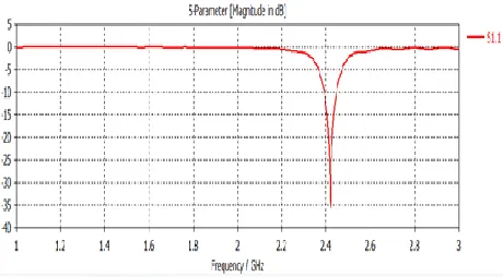
Fig 9 Return loss for Aluminum ground material.
The return loss obtained using Aluminum as a ground material is -36.557 at 2.4 GHz Frequency.
Fig 10 VSWR for Aluminum ground material.
The VSWR obtained using Aluminum as a ground material is 1.035 at 2.4 GHz Frequency.
Fig 11 Far Field for Aluminum ground material.
The gain obtained using Aluminum as a ground material is 6.08 at 2.4 GHz Frequency.
4.3 Copper (annealed) as ground material:
Fig 12 The patch antenna with Copper (annealed) as ground material
The patch antenna with Copper (annealed) as ground material.
3910
The return loss obtained using Copper (annealed) as a ground material is -45.742 at 2.4 GHz Frequency.
Fig 14 VSWR for copper (annealed) as ground material.
The VSWR obtained using Copper (annealed) as a ground material is 1.012 at 2.4 GHz
Fig 15 Far Field for copper (annealed) as ground material.
The Far Field obtained using Copper (annealed) as a ground material is 6.07dBi at 2.4 GHz Frequency.
Table 2 for comparison of results with various grounds
S.N
o Parameters Model 1 Model 2 Model 3 1 Ground platinum Aluminum Copper(annealed
) 2 Substrate FR-4
(lossy)
FR-4
(lossy) FR-4 (lossy)
3 Patch
Copper (annealed
)
Copper (annealed
)
Copper (annealed) 4
Reflection coefficient
(dB)
-35.481 -36.557 -45.742
5
Voltage Standing Wave
Ratio(VSWR)
1.241 1.035 1.012
6 Bandwidth(Mhz
) 53 60 55
7
Resonant Frequency(Ghz
)
2.418 2.42 2.42
8 Gain(dBi) 6.083 6.083 6.073
5.CONCLUSIONS
The rectangular microstrip antenna is designed and tested with three different ground materials namely Platinum, Aluminum, Copper (annealed) using CST Studio software. The return losses obtained for platinum and aluminum are nearly equal which is -35dB whereas for the microstrip
antenna with copper (annealed) as ground has got significant and enhanced result i.e, return losses are -45.742dB at 2.4GHz . Also for this antenna a sufficient bandwidth is introduced via the microstrip feed line at the desired resonant frequency of 2.4GHz is achieved. As mentioned above the designed Microstrip Patch antenna is optimized such that it covers WLAN.
REFERENCES:
[1] R. Garg, P. Bhartia, I. Bahl, and A. Ittipiboon, Microstrip Antenna Design Handbook, Artech House, 2000. [2] C. A. Balanis, “Antenna Theory, Analysis and Design,”
John Wiley & Sons, New York, 1997.
[3] D. M. Pozar and D. H. Schaubert, Microstrip Antennas: The Analysis and Design of Microstrip Antennas and Arrays, IEEE Press, 1995.
[4] K. F. Lee, Ed., Advances in Microstrip and Printed Antennas, John Wiley, 1997.
[5] F. E. Gardiol, “Broadband Patch Antennas,” Artech House.
[6] D. R. Jackson and J. T. Williams, “A comparison of CAD models for radiation from rectangular microstrip patches,” Intl. Journal of Microwave and Millimeter-Wave Computer-Aided Design, Vol. 1, No. 2, pp. 236-248, April 1991.
[7] D. M. Pozar, “A reciprocity method of analysis for printed slot and slot- coupled microstrip antennas,” IEEE Trans. Antennas and Propagation, vol. AP-34, pp. 1439-1446, Dec. 1986.
[8] H. Pues and A Van de Capelle, “Accurate transmission-line model for the rectangular microstrip antenna,” Proc. IEE, vol. 131, pt. H, no. 6, pp. 334-340, Dec. 1984.
[9] K. Karuna Kumari, Dr. P. V. Sridevi “Performance Evaluation of Circular Microstrip Patch antenna array with different Dielectric substrate” International journal of Electronics and Communication Engineering &Technology (IJECET), 4(1), 236 - 249.(Feb 2013) [10] K. Karuna Kumari1, Prof.P.V.Sridevi “Design and
Analysis of Microstrip Antenna Array Using CST Software” International Journal of Engineering Science and Computing (IJESC), May 2016, Vol.6, Issue-5, pp. 5977- 5982.
[11] Gujarathi Thrivikram, P.Chandrasekhar, K.Karuna kumari “Study on Fractal Circular Shaped Microstrip Antenna at 6.48 GHz” International Journal of Scientific Development and Research (IJSDR) 2016, Vol.1, Issue-3, pp.91-94.
[12] S K Behera, “Novel Tuned Rectangular Patch Antenna As a Load for Phase Power Combining” Ph.D Thesis, Jadavpur University, Kolkata.
[14] D. R. Jackson, S. A. Long, J. T. Williams, and V. B. Davis, “Computer-aided design of rectangular microstrip antennas”, ch. 5 of Advances in Microstrip and Printed Antennas, K. F. Lee, Editor, John Wiley, 1997.
[15] R.J. Garbaez and R. H. Turpin, “A generalized expansion for radiated and scattered fields”, IEEE Transactions on Antennas and Propagation, vol. AP-19, May 1971.
3911
Transactions on Antennas and Propagation, vol. AP-19, September 1971.