An Efficient Radar Transmission System
Using RF photonics
Rohit Chhabra1, Abhishek Yadav2, Sudhanshu Shekhar3, Sonali Dash4
UG Student, Dept. of E&TC, Bharati Vidyapeeth Deemed University, College of Engineering, Pune, Maharashtra,
India 1, 2, 3
Assistant professor, Dept. of E&TC, Bharati Vidyapeeth Deemed University, College of Engineering, Pune,
Maharashtra, India 4
ABSTRACT:A radar is a device which is used for detection of objects using radio waves and it determines the
velocity, range or angle of objects. A radar can be used to detect aircraft, weather formations, space crafts, motor vehicles, ships, etc. It consists of a transmitting section which produces electromagnetic waves generally of high frequencies, a transmitting antenna, a receiving antenna (most often a single antenna serves the purpose of both the transmitting and receiving antenna), and a receiver and a digital/analog signal processor to determine the properties of the object. In order to build an efficient radar system, the carrier signal should be of high frequency, must have low phase noise and should be phase stable for high resolution .In this paper, it proposes an optics based optoelectronic oscillator for high frequency generation and low phase noise output.
KEYWORDS:Radar, Optoelectronic oscillator, High Frequency, Quality factor, Phase noise.
I.INTRODUCTION
Radar has been in use for a long time and is a very important invention of the 20th century. It can be used to detect distance, position or speed of a target by transmitting an electromagnetic signal and then by receiving the reflected wave. Since world war-II no significant change in radar system were made.
The only changes introduced in modern radar system was the use of digital electronics for signal processing. Advancement in radar system are bounded by the use of electrical radio frequency component.
To improve the radar sensitivity and efficiency, one has to improve the front end architecture of the radar system. The use of electrical oscillators in radars for high frequency generation are limited up to a frequency of 2 GHz. For higher frequency generation in electrical oscillator, frequency up-conversion is implemented. When working with basic electronic oscillators we are able to generate signals with frequency up to some tens of GHz by multiplying low frequency. A major disadvantage of using frequency up conversion for generation of frequency higher than 2GHz is the introduction of phase noise in the oscillator output.
This phase noise increase with increasing oscillator frequency. In a traditional way, electronic oscillators are capable of satisfying the phase noise criteria for low frequency application.
When the frequency is increased beyond a few GHz, because of frequency multiplication, electronic oscillator create more unwanted noise. In devices which function at ultra-high frequencies (such as Doppler radar, satellite communication) high performance oscillation are required.
To overcome this limitation of phase noise in electrical oscillator, we have adopted the use of RF-photonics in implementation of an opto-electronic oscillator. One potential candidate to meet this requirement is opto-electronics oscillator.
Figure 1: Conventional electrical waveform generator in Radar.
II) OPTO ELECTRONIC OSCILLATOR (OEO)
The initial work related to OEO was conducted by Neyer & Voges, when they analyzed the opto electronics feedback circuit in 1982. However, a couple of years later in 1994, X.S. Yao and L. Maleki, two researcher of NASA jet propulsion laboratory invented the opto-electronic oscillator. In 1995 Yao & Maleki introduced this oscillator as a light induced microwave oscillator (LIMO). Later in 1996,s two new descriptions of OEO were published.
The main aim of this oscillation was to generate ultra-high frequency signals with particularly low phase noise. This system was developed for a new generation of radars to completely replace microwave frequency generators.
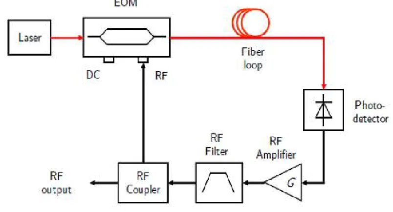
The basic structure of OEO is shown in figure2.
As shown, an OEO consists of both optical and electronic links. The main component of an optoelectronic oscillator is a continuous wave laser source .The light from continuous wave laser source is introduced into an EOM-electro optic modulator (Mach-Zehnder Modulator). It can also be an optical mini-resonator coupled to the optical fibre at the output of the phase modulator.After traveling through a fibre optic loop which also acts as a resonating element and is equivalent of an optical delay line, it is incident on a photo diode which converts the optical signal to RF signal.
The RF signal is than amplified, filtered and divided into two ways using a RF coupler. One output of coupler goes to be EOM which completes the feedback loop for continuous oscillation, while the other output is used for spectrum analysis.
III. SYSTEM MODEL
A basic oscillator consists of an amplifier with gain G and a feedback transfer function β (f) in a closed loop. The gain G compensates for the losses of the loop, while β (f) selects the oscillation frequency. Barkhausen condition of
sustained oscillations gives G.β (f) = 1. OEO is characterized in the optical domain. It is capable of having high quality
factor and stable microwave electric signal in form of sine/cosine when continuous light wave is given to OEO system. This oscillator works on principle of converting light wave to electrical signal.
In an OEO, the length of optical fibre is usually and long it is used as an optical energy storage element for the microwaves signal modulated on the optical carrier. A long fibre result in a longer energy decay time and therefore a relatively low phase noise for the microwave signal generated by the Optoelectronic oscillator. Using long fibre results in narrow frequency spacing between the Eigen modes circulating in OEO cavity. Thus usually an ultra-narrow band electronic band pass filter is used for mode selection.
In this design we have used 1550nm light because of less attenuation and less dispersion during communication. This 1550 nm light is introduced from a continuous wave laser to MZ modulator which has its own bias and one more electrical signal. Intensity modulation in MZ modulator takes place and the modulated light from modulator is passed through fiber which is acting as energy storing element depending on length of fibre.
Output from optical fibre is passed through photo detector which converts all delayed optical signal to electrical signal. But photo detector also generates harmonics during conversion process hence a narrow band pass filter is put to extract desire signal with high quality factor. And after amplification electrical signal is fed back to modulator and feedback loop is completed. This configuration supports self-sustained oscillation at frequency determined by the fibre delay length and band pass filter property.
Quality factor for such oscillatory system can be calculated by Q = 2πfτd, where f is frequency of electrical signal and τd is time delay occur due to fibre. Thus we have developed regenerative feedback approach to produce electrical stable
IV. RESULT AND DISCUSSION
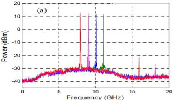
Figure 3- Frequency vs. Amplitude graph of the Oscillator Output
Figure 4-The spectrum for the generated 10 GHz RF signal, span = 20 GHz.
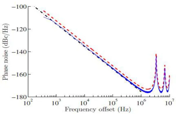
Figure 6 -Graph of phase noise for a generated RF signal vs. Offset frequency.
A lot of peaks are coming into picture as shown in figure 6. These peaks represents the harmonics generated by photo detector during conversion of light wave to electrical signal.
V. CONCLUSION
We have successfully developed a comprehensive simulation model to study the optoelectronic oscillator. Our model generalizes the previously published model by Yao and Maleki. We have introduced a fairly stable, spectrally pure optoelectronic oscillator to achieve low phase noise electrical microwave signals. We have generated 10GHz sinusoidal signal with high quality factor and relatively low phase noise using optoelectronic oscillator. OEO simulations uses blocks of CW Laser, MZ Modulator, Fiber optic cable, Photo detector, band pass filter and RF amplifier. This model can be extended to examine the impact of different amplifier and modulator designs, investigate the source of experimentally observed mode hopping and determine the requirements to suppress it, and to investigate a variety of dual loop configurations.
REFERENCES
[1] D. B. Leeson, "A simple model of feedback oscillator noise spectrum," Proc. IEEE, vol. 54, pp. 329-330, 1966.
[2] X. S. Yao and L. Maleki, “High frequency optical subcarrier generator” Electronic Letters, vol. 30, no. 18, pp. 1525 – 1526, Sept. 1994. [3] Cox, C.H., III; Ackerman, E.I.; Betts, G.E.; Prince, J.L. IEEE Transaction on Microwave Theory and Techniques, vol. 54, no 2, pp. 906-920,
2006.
[4] X. S. Yao and L. Maleki, “Dual microwave and optical oscillator,” Opt. Lett. 22, 1867–1869 (1997). [5] M. Skolnik, “Introduction to radar systems”, McGraw-Hill, 1981.
[6] X. Steve Yao and Lute Maleki, “Optoelectronic microwave oscillator”, Vol. 13, No. 8/August 1996/ J. Opt. Soc. Am. B
[7] K. Volyanskiy, J. Cussey, H. Tavernier, P. Salzenstein, G. Sauvage, L. Larger, and E. Rubiola,"Applications of the optical fiber to the generation and measurement of low-phase-noise microwave signals," J. Opt. Soc. Am. B 25(12), 2140-2150 (2008)
[8] Optical Filter, Wikipedia
[9] X. S. Yao and L. Maleki, “Converting light into spectrally pure microwave oscillation,” Opt. Lett. 21, 483–485 (1996). [10] X. S. Yao and L. Maleki, “Multi-loop optoelectronic oscillator,” IEEE J. Quantum Electron. 36, 79–84 (2000).
[13] I. S. Grudinin, V. S. Ilchenko, L. Maleki, Ultrahigh optical Q factors of crystalline resonators in the linear regime, Phys. Rev. A 74, 063806(9) (2006)
[14] V. S. Ilchenko, A. A. Savchenkov, A. B. Matsko, D. Seidel, L. Maleki, Crystalline resonators add properties to photonic devices, 17 February 2010, SPIE Newsroom. DOI: 10.1117/2.1201002.002536 (2010)
[15] V. S. Ilchenko, X. S. Yao, and L.e Maleki, High-Q microsphere cavity for laser stabilization and optoelectronic microwave oscillator, Proc. SPIE, 3611, 190 (1999)
[16] A. Neyer, E. Voges, High frequency electro optic oscillator using an integrated interferometer, Appl. Phys. Lett. 40(1), 6-8 (1982)
[17] J. Poirson, F. Bretenaker, M. Vallet, A. Le Floch, Analytical and experimental study of ringing effects in a Fabry–Perot cavity. Application to the measurement of high finesses, J. Opt. Soc. Am. B 14(11), 2811-2817 (1997)
[18] V. G. Plotnichenko, V. O. Sokolov, and E. M. Dianov, Hydroxyl Groups in High-Purity Silica Glass, Inorganic Materials, 36(4), 404-410 (2000)