A Battery Storage System Based On Modified
DC-DC Converter Using MANFIS Algorithm
M.Revathi, V.Dhinesh, P.M.Manikandan, Dr. S.Saravanan,Me.,Ph.D., Dr.S.Sakthivel
PG Student, Dept. of Electrical and Electronics Engineering, Muthayammal Engineering College, Namakkal, Tamil Nadu, India
PG Student, Dept. of Electrical and Electronics Engineering, Muthayammal Engineering College, Namakkal, Tamil Nadu, India
PG Student, Dept. of Electrical and Electronics Engineering, Muthayammal Engineering College, Namakkal, Tamil Nadu, India
Professor and Head/ EEE(UG), Dept. of Electrical and Electronics Engineering, Muthayammal Engineering College, Namakkal, Tamil Nadu, India
Professor and Head/ EEE(PG), Dept. of Electrical and Electronics Engineering, Muthayammal Engineering College, Namakkal, Tamil Nadu, India
ABSTRACT: Power supplies with active Power Factor Correction techniques are becoming necessary for many types of electronic equipments to meet harmonic regulation. Recently most of the power factor corrected rectifier utilizes a boost converter at this front end. This conventional Power Factor Correction (PFC) scheme has lower efficiency due to significant losses in the diode bridge. During each switching cycle, the current flows through three power semiconductor devices. As a result, a significant conduction loss, caused by the forward voltage drop across the bridge diode, may degrade the converter’s efficiency, especially at low line input voltage. In this paper, to maximize the power supply efficiency and to improve power factor, a bridgeless cuk rectifier for PFC are proposed, where the number of semiconductors switches generating losses is reduced by essentially eliminating the full bridge input diode rectifier. The dynamic performance of the proposed cuk converter with MANFIS control scheme are analyzed and compared in the form of power factor and total harmonic distortion.
KEYWORDS: power factor correction, CUK converter, proportional integral, MANFIS algorithm.
I. INTRODUCTION
The equipment connected to an electricity distribution network usually needs some kind of power conditioning, typically rectification, which produces a non sinusoidal line current due to the nonlinear input characteristic. The most significant examples of nonlinear loads are reviewed next. Line-frequency diode rectifiers convert AC input voltage into DC output voltage in an uncontrolled manner (1). Single-phase diode rectifiers are needed in relatively low power equipment that need some kind of power conditioning, such as electronic equipment (e.g. TVs, office equipment, battery chargers electronic ballasts) and household appliances. For higher power, three phase diode rectifiers are used, e.g. in variable-speed drives and industrial equipment. In both single- and three-phase rectifiers, a large filtering capacitor is connected across the rectifier output to obtain DC output voltage with low ripple. As a consequence, the line current is non sinusoidal.
capabilities or for controlling the light intensity in incandescent lamps or the temperature in resistive heaters. In every case, the line current is non sinusoidal (6). Gas discharge lamps with line-frequency ballast are nonlinear loads, as well. Hence, their line current is non sinusoidal. In line application, maintaining a high efficiency across the entire line range poses a major challenge for ac to dc rectifiers that require power factor correction (PFC). The cuk power factor rectifier that further. The single phase AC-DC bridgeless rectifier based on cuk topology is presented and its performance is analyzed. This proposed cuk derived rectifier topology reduces the conduction and switching loss. Thus it improves the conversion efficiency compared with other types of power factor correction circuit (4). It also provides reduction in size of power factor inductor and EMI filters. The power factor is also improved with reduction in line current harmonics.
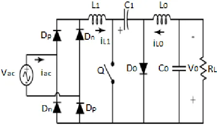
II. CUK CONVERTER
The Cuk converter is a type of DC-DC converter that has an output voltage magnitude that is either greater than or less than the input voltage magnitude. the non-isolated Cuk converter can only have opposite polarity between input and output. It uses a Capacitor as its main energy-storage component, unlike most other types of converters which use an Inductor.. Because the power transfer flows continuously via the capacitor, this type of switcher has minimized Electro Magnetic Interference (EMI) radiation [3]. The Cuk converter enables the energy flow bi-directionally, by adding a diode and a switch. The two inductors L1 and L2 are used to convert respectively the input voltage source (Vi)
and the output voltage source (Co) into current sources. Indeed, at a short time scale an inductor can be considered as a
current source as it maintains a constant current. This conversion is necessary because if the capacitor were connected directly to the voltage source, the current would be limited only by (parasitic) resistance, resulting in high energy loss.
Figure 3.1 Conventional Cuk converter A. Continuous Conduction Mode
In steady state, the energy stored in the inductors has to remain the same at the beginning and at the end of a commutation cycle. The energy in an inductor is given by,
E = Li2 (2.1)
It implies that the current through the inductors has to be the same at the beginning and the end of the commutation cycle. As the evolution of the current through an inductor is related to the voltage across it
E = LdI/dt (2.2)
In the off-state, inductor L1 is connected in series with Vi and CL1=Vi-Vc. As the diode D is forward biased (we
consider zero voltage drop), L2 is directly connected to the output capacitor. Therefore VL2=V0In the on-state, inductor
L1 is directly connected to the input source. Therefore, Inductor L2 is connected in series with C and the output
capacitor, so VL2=V0.The converter operates in on-state from t=0 to t=DT (D is the duty cycle), and in off state from
DT to T (that is, during a period equal to (1-D)/T). The average values of VL1 and VL2 are therefore as both average
Vc=-V0/D (2.3)
B.Discontinuous Conduction Mode
Like all DC-DC converters Cuk converters rely on the ability of the inductors in the circuit to provide continuous current, in much the same way a capacitor in a rectifier filter provides continuous voltage. If this inductor is too small or below the critical inductance, then the current will be discontinuous. The transformer action between the
inductors inside that component gives a coupled inductor Cuk converter lower output ripple than a Ćuk converter using
two independent discrete inductor components.
III. CONVENTIONAL CONTROLLER
A. Proportional controller
The Proportional-Integral (PI) algorithm computers and transmits a Controller Output (CO) signal every sample time, T, to the final control element (e.g., valve, variable speed pump). The computed CO from the PI algorithm is influenced by the controller tuning parameters and the controller error, e(t).PI controllers have two tuning parameters to adjust. While this makes them more challenging to tune than a P-Only controller, they are not as complex as the three parameter PID controller. Integral action enables PI controllers to eliminate offset, a major weakness of a P-only controller. Thus, PI controllers provide a balance of complexity and capability that makes them by far the most widely used algorithm in process control applications [9].The PI Algorithm While different vendors cast what is essentially the same algorithm in different forms, here we explore what is variously described as the dependent, ideal, continuous, position form.
B. Fuzzy logic controller
Fuzzy logic is widely used in machine control. The term itself inspires a certain skepticism, sounding equivalent to half-baked logic or bogus logic, but the "fuzzy" part does not refer to a lack of rigour in the method, rather to the fact that the logic involved can deal with concepts that cannot be expressed as true or false as well as fuzzy logic in many cases, fuzzy logic has the advantage that the solution to the problem can be cast in terms that human operators can understand, so that their experience can be used in the design of the controller. Fuzzy logic is widely used in machine control. The term itself inspires a certain skepticism, sounding equivalent to half-baked logic or bogus logic, but the "fuzzy" part does not refer to a lack of rigour in the method, rather to the fact that the logic involved can deal with concepts that cannot be expressed as true or false as well as fuzzy logic in many cases, fuzzy logic has the advantage that the solution to the problem can be cast in terms that human operators can understand, so that their experience can be used in the design of the controller.
C. Fuzzification
Fuzzification is the process of making a crisp quantity to fuzzy. We do this by simply resigning that many of the quantities that we consider to be crisp and deterministic are actually not deterministic at all. They carry considerable uncertainty. If the form of uncertainty happens to arise because of imprecision, ambiguity or vagueness, then the variable is probably fuzzy and can be represented by a membership function. A fuzzification process the function that it converts crisp data into fuzzy sets. The fuzzification converts the input data into suitable linguistic values, which may be viewed as labels of fuzzy sets.
D. Membership Function
member of the fuzzy set; the value 1 means that X is fully a member of the fuzzy set. The values between 0 and 1 characterize fuzzy members, which belong to the fuzzy set only partially shown in figure
Sometimes, a more general definition is used, where membership functions take values in an arbitrary fixed algebra or structure L usually it is required that L be at least a posset or lattice. The usual membership functions with values in [0, 1] are then called [0, 1]-valued membership functions is illustrated in fig 5.5.
E. Membership Function Pictorial Representation
The Membership Function (MF) of the associated input and output linguistic variables is generally predefined on a common universe of discourse. For the proposed system, the input and output membership functions are shown in figure 5.3, 5.4 and 5.5. For the successful design of FLC’s proper selection of input and output scaling factors (gains) or tuning of the other controller parameters are crucial jobs, which in many cases are done through.
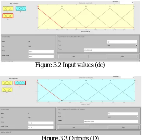
Figure 3.1 Input values (e)
Fuzzy logic controller membership function for FIS variable is de given as the most common shape of membership functions is triangular, although trapezoidal and bell curves are also used, but the shape is generally less important than the number of curves and their placement. From three to seven curves are generally appropriate to cover the required range of an input value, or the "universe of discourse" The input e and de are given in 5.2 and 5.3 the corresponding output variable generated D. the output D is duty cycle.
Figure 3.2 Input values (de)
Figure 3.3 Outputs (D)
The main characteristics steps of the fuzzy logic controller are
Five fuzzy sets for each of two inputs error in speed and change in error in speed. Error interval ranges from [-20 [-20] and change error interval ranges from [-5 5].
Five fuzzy sets for the output duty cycle [0 1].
Triangular membership function.
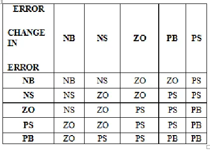
Rule base was formed using a 5*5 matrix.
Fuzzify the inputs to the controller.
Inference mechanism based on fuzzy implication.
Defuzzification using the “centre of area” method. F. Fuzzy Control
Fuzzy controllers are very simple conceptually. They consist of an input stage, a processing stage, and an output stage. The input stage maps sensor or other inputs, such as switches, thumbwheels, and so on, to the appropriate membership functions and truth values. The processing stage invokes each appropriate rule and generates a result for each, then combines the results of the rules. Finally, the output stage converts the combined result back into a specific control output value. The most common shape of membership functions is triangular, although trapezoidal and bell curves are also used, but the shape is generally less important than the number of curves and their placement. As discussed earlier, the processing stage is based on a collection of logic rules in the form of IF-THEN statements, where the IF part is called the "antecedent" and the THEN part is called the "consequent". Typical fuzzy control systems have dozens of rules. Fuzzy control system design is based on empirical methods, basically a methodical approach to trial-and-error. The general process is as follows:
Document the system's operational specifications and inputs and outputs.
Document the fuzzy sets for the inputs.
Document the rule set.
Determine the defuzzification method.
Run through test suite to validate system, adjust details as required.
Complete document and release to production.
As a general example, consider the design of a fuzzy controller for a steam turbine. The Surface Viewer has a special capability that is very helpful in cases with two (or more) inputs and one output, you can actually grab the axes and reposition them to get a different three-dimensional view on the data. The Refered Input field is used in situations when there are more inputs required by the system than the surface is mapping. The Surface Viewer can generate a three-dimensional output surface where any two of the inputs vary, but two of the inputs must be held constant since computer monitors cannot display a five-dimensional shape. When we move beyond three dimensions overall, we start to encounter trouble displaying the results. Just below the pop-up menus are two text input fields that let you determine how many x-axis and y-axis grid lines you want to include. The scaling factors are used to normalize the different range of input/output signals into the universe of discourse [-1, 1] and thus can generalize and facilitate the design and configuration of the fuzzy controller. However, unsuitable SF’s for the input/output signals can worsen transient and steady state response, while the scopes of input/output signals, as the scaling factors, are safe but conservative.
The fuzzy rule base assemblies plant information and apply the human control expertise to the given problem. For a two-input-one-output fuzzy controller, the form of rules can be Rule: if (input X1 is A) and (input X2 is B)
then (output Y is C). The rules may use several variables both in condition and conclusion of the rules. The typical single input single output problem is to regulate a control signal based on an error signal. The controller may actually need both the error, the change in error, and the accumulated error as inputs, but we will call it single-loop control, because in principle all three are formed from the error measurement. A fuzzification interface, the fuzzy control initially converts the crisp error and its rate of change in displacement into fuzzy variables; then they are mapped into linguistic labels.
referenced by the antecedent, or the if-part of each rule. The third column of plots (blue plots) shows the membership functions referenced by the consequent, or the then-part of each rule. Since it plots every part of every rule, it can become unwieldy for particularly large systems, but, for a relatively small number of inputs and outputs, it performs well (depending on how much screen space you devote to it) with up to 30 rules and as many as 6 or7 variables. The inference engine control is based on the frequent reevaluation of the data store states, not on any static control structure of the program.
Table 4.1 Rule table for fuzzy logic controller E.Inference Engine
The decision making logic or inference engine has the capability of simulating human reasoning based fuzzy concepts and of inferring with fuzzy actions by employing the rules of inference. Fuzzy inference is the process of formulating the mapping from a given input to an output using fuzzy logic. The mapping then provides a basis from which decisions can be made, or patterns discerned. There are various types of fuzzy inference systems that can be implemented. Based on the fuzzy inference systems, fuzzy decision table has been formed through which the output of the fuzzy logic controllers determined.
F.Defuzzification
Defuzzification is the process of producing a quantifiable result in fuzzy logic, given fuzzy sets and corresponding membership degrees. It is typically needed in fuzzy control systems. These will have a number of rules that transform a number of variables into a fuzzy result, that is, the result is described in terms of membership in fuzzy sets. For example, rules designed to decide how much pressure to apply might result in Decrease Pressure (15%), Maintain Pressure (34%), and Increase Pressure (72%)". Defuzzification is interpreting the membership degrees of the fuzzy sets into a specific decision or real value. The simplest but least useful defuzzification method is to choose the set with the highest membership, in this case, "Increase Pressure" since it has a 72% membership, and ignore the others, and convert this 72% to some number. The problem with this approach is that it loses information. The rules that called for decreasing or maintaining pressure might as well have not been there in this case.
IV. SIMULATION RESULTS AND DISCUSSION
Figure 5.1 Power factor display after using PI controller
The Input voltage and current waveform of proposed circuit is shown in figure 5.2. Here the input current drawn by the diode rectifier is not a pure AC. The THD obtained for this PI controller with PFC topology is 4.762%.
Figure 5.2 Input Voltage and Current waveform of cuk derived PFC topology with PI controller
Figure 5.3 Proposed cuk rectifier with PI controller
The output voltage waveform of cuk derived PFC topology with PI controller is shown in figure 5.4 and its output value V0=52 volts .The output voltage waveform of cuk derived PFC topology with PI controller is 5.4 and its
Figure 5.4 Output voltage waveform for PI Controller
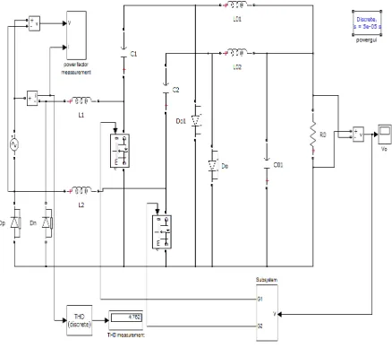
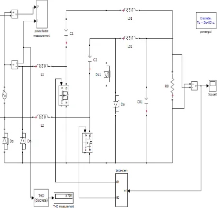
Figure 5.5 Simulation circuit of cuk rectifier with Fuzzy Logic controller
The functional block of fuzzy logic controller is shown in figure 5.6 and the power factor is displayed. The obtained power factor is 0.9997.The Input voltage and current waveform of proposed circuit is shown in figure 5.7. Here the input current drawn by the diode rectifier is not a pure AC
The THD obtained for this PFC topology is given fig 5.6 the THD obtained for the application of fuzzy logic controller with PFC topology is 3.76. The output voltage waveform of cuk derived PFC topology is shown in figure 5.8 and its output value V0=48 volts.
Figure 5.7 Input Voltage and Current Waveform with fuzzy logic controller
Figure 5.8 Output voltage waveform for fuzzy logic controller.
The output voltage waveform of cuk derived PFC topology with fuzzy logic controller is shown in figure 5.8 and itsoutput value Vo =52 Volts.
VI. CONCLUSION
The single phase AC-DC bridgeless rectifier based on cuk topology is presented and its performance is analyzed. This proposed cuk derived Type 3 rectifier topology reduces the conduction and switching loss. Thus it improves the conversion efficiency compared with other types of power factor correction circuit. It also provides reduction in size of power factor inductor and EMI filters. The power factor is also improved with reduction in line current harmonics. The PI controller and Fuzzy Logic Controller are implemented with this proposed circuit in order to improve the power factor. The simulation is performed for this proposed circuit and the results are verified. The result shows that the fuzzy logic controller gives better power factor correction compared to Pi with this proposed power factor correction circuit.
REFERENCES
[1] Dongsheng Ma, Janet Wang, and Minkyu Song, “Adaptive On-Chip Power Supply With Robust One-Cycle Control Technique,” IEEE Transactions on Very Large Scale Integration (VLSI) Systems, Vol. 16, No. 9, September 2008.
[2] Hongbo Ma, Jih-Sheng Lai, Quanyuan Feng, Wensong Yu, Cong Zheng, and Zheng Zhao, “A Novel Valley-Fill SEPIC-derived Power Supply Without Electrolytic Capacitors for LED Lighting Application,” IEEE Transactions On Power Electronics, Vol. 27, No. 6, June 2012. [3] Huang-Jen Chiu, Yu-Kang Lo, Jun-Ting Chen, Shih-Jen Cheng, Chung-Yi Lin and Shann-Chyi Mou “A High-Efficiency Dimmable LED
Driver for Low-Power Lighting Applications,” IEEE Transactions on Industrial Electronics, Vol. 57, No. 2, February 2010.
[5] Keyue M. Smedley and Slobodan Cuk, “One-Cycle Control of Switching Converters,” IEEE Transactions on Power Electronics, Vol. 10, No. 6, November 1995.
[6] R. Redl, “Power-factor correction in single-phase switching-mode power supplies. An overview,” Int. J. Electron., vol. 77, no. 5, pp. 555–582, 1994.
[7] K.V.Hari Prasad,CH.Uma Maheswar Rao and A.Sri Hari “Design and Simulationof A Fuzzy Logic Controller for Buck & Boost Converters,” International Journal Advanced Technology& Engineering Research, Vol. 2, Issue 3, 2012.
Ray-Lee Lin, and Hsu-Ming Shih (2009),“Piezoelectric Transformer Based Current-Source Charge-Pump Power-Factor-Correction Electronic Ballast,” IEEE transactions on power electronics, Vol. 23, No. 3.pp.484-496.
[8] SumanDwari, and Leila Parsa, (2010),“An Efficient AC–DC Step-Up Converter for Low-Voltage Energy Harvesting,” IEEE transactions on power electronics, Vol. 25, No. 8.pp 920-932