International Journal of Research
Available at https://edupediapublications.org/journalsp-ISSN: 2348-6848 e-ISSN: 2348-795X Volume 03 Issue 17
November 2016
Power Quality Improvement in Grid Connected System with Fuzzy
Logic Controller At Distribution Level
Kongari Ramesh
M-tech student Scholar
Department of Electrical & Electronics Engineering, DVR Engineering College, KANDI;
MEDAK(Dt); Telangana, India. Email:[email protected]
K.Prashant
HOD
Department of Electrical & Electronics Engineering, DVR Engineering College, KANDI;
MEDAK (Dt); Telangana, India. Email:[email protected]
Abstract— The depletion of the fossil fuel resources and
the global warming effects has led the world to think seriously of other alternative sources of energy. So renewable energy resources (RES) are being connected to the distribution systems, mostly done by using power electronic converters. But use of power electronic converters and non-linear loads like at distribution level injects harmonics, which intern cause power quality problems. Distribution static compensator (DSTATCOM) is very popular in compensating power problems for nonlinear and unbalanced loads. Any change in the load affects the DC-link voltage (DCLV) directly. Conventionally, a PI controller is used to maintain the DCLV to the reference value, but its transient response is poor. So, fuzzy logic controller is proposed which shows better dynamic response. To trigger inverter HCC is used. The proposed inverter with the control when connected to wind energy, helps the 3-phase 4-wire linear/non-linear unbalanced load at point of common coupling appear as balanced linear load to the grid. With MATLAB/Simulink simulation studies, the proposed control technique is demonstrated and evaluated here.
Key Words - distributed generation (DG), distribution system, grid interconnection, power quality (PQ), renewable energy, Point of common coupling (PCC).
I. INTRODUCTION
Utilization of electrical energy indicates the standard of living of country. In Developing countries like India the
economy of a country solely depends on
industrialization, which in turn require bulk amount of electrical energy. Also, irrigation, domestic and commercial sectors require bulk amount of electrical energy. Since, electrical energy is Superior compared to other energy forms because it can be generated in bulk amount , transmitted to longer distances and converted to any other form easily, flexible control and cheap. Most of electrical energy demand is supplied by conventional sources like coal, petroleum and gas which are non-renewable and exhaust after some decades. In India around 70% of electrical energy is from coal which is diminishing and also it is producing lot of pollution which in turn causes globalization. So, this is an important issue which has motivated nations across the world to think about alternative forms of energy which utilize inexhaustible and environmentally friendly natural resources like solar, wind and tidal energies. But these sources can’t be generated in huge amounts.
typically wind or sun. So for the reliable operation of the system, continuous control is needed that is power quality (PQ) is major concern in supplying electrical energy to the customers.
Electric Power quality is a term which has captured increasing attention in power engineering in the recent years. Even though this subject has always been of interest to power engineers, it has assumed considerable interest in the 1990's. Electric power quality means different things for different people. To most electric power engineers, the term refers to a certain sufficiently high grade of electric service but beyond that there is no universal agreement. The measure of power quality depends upon the needs of the equipment that is being supplied. What is good power quality for an electric motor may not be good enough for a personal computer.
II.SCOPE AND MITIGATION OF PQ PROBLEMS
Usually the term power quality refers to maintaining a sinusoidal waveform of bus voltages at rated voltage and frequency. Otherwise PQ Problems like voltage flickers, poor power factor and harmonics are occurred. These problems are due to large amount of induction motors, adjustable speed drives, Switching Power supplies, Arc furnaces, Non- linear loads and power electronic devices used in DG Systems. The characteristics of load have become more complex due to the increased use of power electronic equipment, which results in a deviation of voltage and current from its sinusoidal waveform.
Also, the restructuring of power systems and with shifting trend towards distributed generation and deregulation, the issue of power quality is going to take newer dimensions. In developing countries, Where the variation of power frequency and many such other determinates of power quality are themselves a serious question, it is very vital to take positive steps in this direction.
Power Devices are introduced to improve Power Quality.
Harmonics and poor power factor will produce effects like reactive power burden, unbalance and excessive neutral current which in turn produce overheating. To compensate harmonics conventional Passive Filters are used for specific number of harmonics. After development of power electronics SVC, Which is composition of Passive LC filters and fixed compensating devices with some degree of variation were employed to improve the power factor of ac loads. Such devices have the demerits of fixed compensation, large size, ageing and resonance. The increased severity of harmonic pollution in power networks has attracted the attention of power electronics and power system engineers to develop dynamic and adjustable solutions to the power quality problems. So, now to compress total harmonic content, power factor improving & for power quality Active Power Filters (APFs) are used. In APFs, DSTATCOM or Shunt APF is popular now.
III. SYSTEM DESCRIPTION
The proposed system consists of RES connected to the dc link of a grid-interfacing inverter as shown in Fig. 1. It is shows that both load are connected that is non-linear load as well as unbalance load at distribution. Grid is connected to step down transformer with reduce voltage level for distribution side as shown in fig. 1. For injecting Renewable energy to grid inverter that is power electronic devices is used. Power electronic devices produces the unwanted harmonics to reduce this shunt active power filter is used. Shunt active power filter is used to compensate load current harmonics by injecting equal but opposite compensating current. In this paper three phase four wire voltage source current controlled inverter is used. Generally three wire inverter is used but in this fourth terminal is used to compensate the neutral current. A voltage source inverter is convert renewable DC energy into Ac with required magnitude, phase angle and frequency. It also converts the DC voltage across storage devices into a set of three phase AC output voltages. It is also capable to generate or absorbs reactive power. If the output voltage of the VSC is greater than AC bus terminal voltages, is said to be in capacitive mode. So, it will compensate the reactive power through AC system. The type of power switch used is an IGBT in anti-parallel with a diode. The three phase four leg VSI is modeled in Simulink by using IGBT. The driving voltage across the inductance determine the maximum di/dt that can be achieved by the filter. A large valve of inductance is better for isolation from the power system and protection from transient distribution it also limit the ability of the active filter to cancel higher order harmonics.
Fig.1. Schematic of Proposed Renewable Based Distributed Generation System.
IV. CONTROL STRATEGY
A. DC-Link Voltage and Power Control Operation Due to the intermittent nature of RES, the generated power is of variable nature. The dc-link plays an important role in transferring this variable power from renewable energy source to the grid. RES are represented as current sources connected to the dc-link of a grid-interfacing inverter. Fig.1.shows the systematic representation of power transfer from the renewable energy resources to the grid via the dc link. The dc-capacitor decoupled the RES from grid and allows the independent control of inverter on either side of dc link. P1 to P8 switching signal of inverter where P 7 and P8 are multiplied with constant zero to compensate the neutral current.
B. Control of Grid Interfacing Inverter
International Journal of Research
Available at https://edupediapublications.org/journalsp-ISSN: 2348-6848 e-ISSN: 2348-795X Volume 03 Issue 17
November 2016
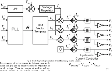
Fig. 2. Block Diagram Representation of Grid-Interfacing Inverter Control.
The exchange of active power in between renewable source and grid can be obtained from the regulation of dc-link voltage. Thus the output of dc-link voltage regulator results in an active current (Im). The multiplication of this active current component (Im) with unity grid voltage vector templates (Ua,Ub, and Uc ) generates the reference grid currents (I*a,I*b , and I*c) for the control process. The reference grid neutral current (I*n) is set to zero, being the instantaneous sum of balanced grid currents. Phase locked loop (PLL) is used to generate unity vector template from which the grid synchronizing angle (0) is obtained.
(1)
(2)
(3)
The actual dc-link voltage (VDC) is sensed and passed through a first-order low pass filter (LPF) to eliminate the presence of switching ripples on the dc link voltage and in the generated reference current signals. The difference of this filtered dc-link voltage and reference dc-link voltage (VDC*) is given to a discrete-PI
(4)
The output of discrete-PI regulator at nth sampling instant is expressed as
(5)
Where KPVdc and KIVdc are proportional and integral gains of dc-voltage regulator. The instantaneous values of reference three phase grid currents are computed as
(6)
(7)
(8)
The reference grid currents (IA*, IB*, IC* and IN) are compared with actual grid currents (IA, IB, IC and IN) to compute the current errors as:
(9)
(10)
(11)
(12)
These current errors are given to hysteresis current controller. The hysteresis controller then generates the switching pulses (P1, P2, P3, P4, P5, P6, P7, and P8) for the gate drives of grid-interfacing inverter.
The switching pattern of each IGBT inside inverter can be formulated on the basis of error between actual and reference current of inverter, which can be explained as:
If IInvA < (IInvA*- hB), then upper switch will be OFF (P1=0) and lower switch S4 will be ON (P4=1) in the phase “A” leg of inverter.
If IInvA > (IInvA*- hB), then upper switch will be ON (P1=1) and lower switch S4 will be OFF (P4=0) in the phase “a” leg of inverter.
Where hb is the width of hysteresis band. Similarly switching pulses are derived for other three leg.
V. INTRODUCTION TO FUZZY LOGIC CONTROLLER
A new language was developed to describe the fuzzy properties of reality, which are very difficult and sometime even impossible to be described using conventional methods. Fuzzy set theory has been widely used in the control area with some application to dc-to-dc converter system. A simple fuzzy logic control is built up by a group of rules based on the human knowledge of system behavior. Matlab/Simulink simulation model is built to study the dynamic behavior of dc-to-dc converter and performance of proposed controllers. Furthermore, design of fuzzy logic controller can provide desirable both small signal and large signal dynamic performance at same time, which is not possible with linear control technique. Thus, fuzzy logic controller has been potential ability to improve the robustness of dc-to-dc converters. The basic scheme of a fuzzy logic controller is shown in Fig 5 and consists of four principal components such as: a fuzzy fication interface, which converts input data into suitable linguistic values; a knowledge base, which consists of a data base with the necessary linguistic
definitions and the control rule set; a decision-making logic which, simulating a human decision process, infer the fuzzy control action from the knowledge of the control rules and linguistic variable definitions; a de-fuzzification interface which yields non fuzzy control action from an inferred fuzzy control action [10].
Fig.3. General structure of the fuzzy logic controller on closed-loop system
The fuzzy control systems are based on expert knowledge that converts the human linguistic concepts into an automatic control strategy without any complicated mathematical model [10]. Simulation is performed in buck converter to verify the proposed fuzzy logic controllers.
Fig.4. Block diagram of the Fuzzy Logic Controller (FLC) for dc-dc converters
Fuzzy Logic Membership Functions:
International Journal of Research
Available at https://edupediapublications.org/journalsp-ISSN: 2348-6848 e-ISSN: 2348-795X Volume 03 Issue 17
November 2016
Fig. 5.The Membership Function plots of error
Fig.6. The Membership Function plots of change error
Fig.7. The Membership Function plots Fuzzy Logic Rules:
The objective of this dissertation is to control the output voltage of the boost converter. The error and change of error of the output voltage will be the inputs of fuzzy logic controller. These 2 inputs are divided into five groups; NB: Negative Big, NS: Negative Small, ZO: Zero Area, PS: Positive small and PB: Positive Big and its parameter [10]. These fuzzy control rules for error and change of error can be referred in the table that is shown in Table II as per below:
Table II
Table rules for error and change of error
VI. SIMULATION RESULTS
For the simulation studies to verify the proposed control approach to achieve multi-objectives for grid interfaced DG systems connected to a 3-phase 4-wire network is
actively controlled. A RES with variable output power is connected on the dc-link of grid-interfacing inverter. On the PCC, an unbalanced 3-phase 4-wire nonlinear load, whose unbalance, harmonics, and reactive power need to be compensated, is connected.
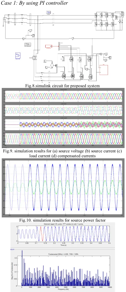
Case 1: By using PI controller
Fig.8.simulink circuit for proposed system
Fig.9. simulation results for (a) source voltage (b) source current (c) load current (d) compensated currents
Fig.10. simulation results for source power factor
Fig.12. simulation results for (a) source voltage (b) source current (c) load current (d) compensated currents
Fig.13. simulation results for source power factor
Fig.14. FFT analysis for source current by using fuzzy controller.
VII.CONCLUSION
This paper presented the control of grid interfacing inverter to improve the power quality at PCC for a
3-phase 4-wire DG System. Grid interfacing inverter can be effectively utilized for power conditioning without affecting its normal operation of power transfer. This inverter can be utilized to inject the power generated from RES to the grid and/or to operate as a shunt Active Power Filter (APF). This process eliminates the need for additional power conditioning equipment to improve of power at PCC. MATLAB/Simulink simulation and Fuzzy logic based results have validated this process and thus this inverter can be utilized as a multifunction device.
REFERENCES
[1] J. M. Guerrero, L. G. de Vicuna, J. Matas, M. Castilla, and J. Miret, “A wireless controller to enhance dynamic performance of parallel inverters in distributed generation systems,” IEEE Trans. Power Electron., vol. 19, no. 5, pp. 1205–1213, Sep. 2004.
[2] J. H. R. Enslin and P. J. M. Heskes, “Harmonic interaction between a large number of distributed power inverters and the distribution network,” IEEE Trans. Power Electron., vol. 19, no. 6, pp. 1586–1593, Nov. 2004.
[3] U. Borup, F. Blaabjerg, and P. N. Enjeti, “Sharing of nonlinear load in parallel-connected three-phase converters,” IEEE Trans. Ind. Appl., vol. 37, no. 6, pp. 1817–1823, Nov./Dec. 2001.
[4] P. Jintakosonwit, H. Fujita, H. Akagi, and S. Ogasawara, “Implementation and performance of cooperative control of shunt active filters for harmonic damping throughout a power distribution system,” IEEE Trans. Ind. Appl., vol. 39, no. 2, pp. 556– 564, Mar./Apr. 2003.
[5] J. P. Pinto, R. Pregitzer, L. F. C. Monteiro, and J. L. Afonso, “3-phase 4-wire shunt active power filter with renewable energy interface,” presented at the Conf. IEEE Rnewable Energy & Power Quality, Seville, Spain, 2007.
[6] F. Blaabjerg, R. Teodorescu, M. Liserre, and A. V. Timbus, “Overview of control and grid synchronization for distributed power generation systems,” IEEE Trans. Ind. Electron., vol. 53, no. 5, pp. 1398–1409, Oct. 2006.
[7] J. M. Carrasco, L. G. Franquelo, J. T. Bialasiewicz, E. Galván, R. C. P. Guisado, M. Á. M. Prats, J. I. León, and N. M. Alfonso, “Powerelectronic systems for the grid integration of renewable energy sources: A survey,” IEEE Trans. Ind. Electron., vol. 53, no. 4, pp.