Vol. 4, Issue 12, December 2015
Reduction of Current Harmonics with FLC
based CSC for Synchronous Drive
Jyothi.D, Prtima Gakhar, Ankita Srivastava
Assistant Professor, Dept. of Electrical & Electronics Engineering, New Horizon College of Engineering, Bangalore, Karnataka,India
Assistant Professor, Dept. of Electrical & Electronics Engineering, New Horizon College of Engineering, Bangalore, Karnataka,India
Assistant Professor, Dept. of Electrical & Electronics Engineering, New Horizon College of Engineering, Bangalore, Karnataka, India
ABSTRACT: This paper presents a performance of the canonical switching cell (CSC) converter fed brushless DC (BLDC) motor drive for power quality (PQ) improvement. The use of CSC not only controlled the DC link voltage but also make the inverter to operate at low frequency so that switching losses are minimized. Moreover the use of front end CSC improves the power factor at AC mains. The system needs only a single voltage sensor for the DC bus voltage sensing; hence the system cost is reduced. The performance was analyzed on the basis of PQ terms of the proposed system under steady state and dynamic conditions. The performance graph has been plotted for the total harmonic distortion (THD) and the power factor (PF). A front end Canonical switching cell converter operating in Discontinuous Inductor Current Mode (DICM) is proposed for PFC operation at AC mains. Fuzzy logic is introduced in order to suppress the chattering and enhancing the robustness of the PFC control system. The results show that the system gives a good PF and the supply current THD as per PQ standard IEC 61000-3-2 for wide range of the motor speed and the supply voltage. The performance has been evaluated using MatLab-Simulink.
KEYWORDS: Diode Bridge Rectifier (DBR), Canonical switching cell (CSC) converter, discontinuous inductor current mode (DICM), Power factor correction (PFC).
I.INTRODUCTION
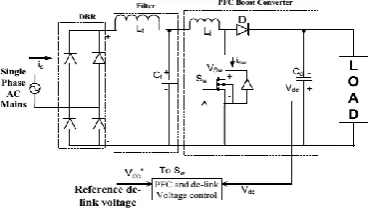
Improving power quality considerations require two factors: achieving high power factor and low harmonics. In fact, a low power factor reduces the power available from the utility grid, while a huge harmonic distortion of the line current causes EMI problems and cross-interferences, through the line impedance, between different systems connected to the same grid. From this point of view, the standard rectifier employing a diode bridge followed by a filter capacitor performs poor. Thus, technologies are being developed to interface systems that improve the power factor of standard electronic loads. Figure 1 shows the conventional system with PFC-boost converter. A front end power factor correction (PFC) is used after the diode bridge rectifier (DBR) for improving the quality of power factor at ac mains [1].
Many topologies of PFC have been reported in the literature surveys. A PFC boost converter has been the most popular configuration [15]. A constant dc-link voltage is maintained at the de-link capacitor for controlling the speed of the drive. Conventional scheme of PFC includes a current multiplier approach which includes voltage and current sensors [2]. The front end SEPIC and Cuk regulator using a variable voltage control have been proposed in [2] and [5], but at the cost of two current sensors. Bridgeless SEPIC regulator of PFC have been proposed in [12], but at the higher cost due to larger inductance. (DBR) for improving the quality of power factor at ac mains This project presents the improvement of power quality using fuzzy based canonical switching cell converter with voltage follower approach. Figure 1 shows the conventional system with PFC-boost converter. A front end power factor correction (PFC) is used after the diode bridge rectifier.
Fig.1 Conventional System with PFC-Boost Converter
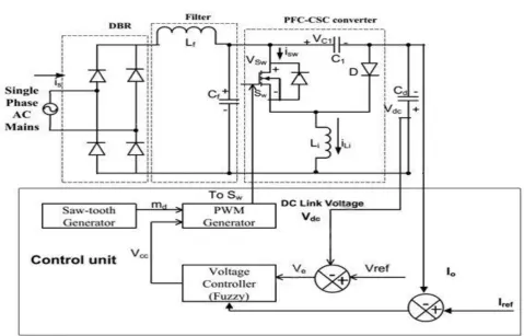
II. PROPOSED FUZZY BASED CANONICAL SWITCHING CELL CONVERTER
Vol. 4, Issue 12, December 2015
Fig. 2 Proposed Fuzzy Based Canonical Switching Cell Converter
III. OPERATING PRINCIPLE OF PFC-BASED CSC CONVERTER
The proposed PFC based CSC Converter operates in DICM. In DICM, the current in inductor Li becomes discontinuous in a switching period (Ts).
Mode I: Figure 3 shows the operation of Mode I operation of CSC converter. The switch Sw is turned ON, the energy from the supply and stored energy in the intermediate capacitor C1 are transferred to inductor Li. In this process, the voltage across the intermediate capacitor Vc1 reduces, while inductor current iLi and dc-link voltage Vdc are increased. The designed value of intermediate capacitor is large enough to hold enough energy such that the voltage across it does not become discontinuous.
Mode II: The switch is turned OFF in this mode of operation. The intermediate capacitor C1 is charged through the supply current while inductor Li starts discharging, hence voltage Vc1 starts increasing, while current iLi decreases in this mode of operation. Figure 4 shows the operation of Mode II operation of CSC converter. Moreover, the voltage across the dc-link capacitor Vdc continues to increase due to discharging of inductor Li.
Fig. 4 Mode II
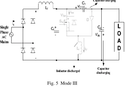
Mode III: This is the discontinuous conduction mode of operation as inductor Li is completely discharged and current iLi becomes zero. Figure 5 shows the operation of Mode III operation of CSC converter. The voltage across the intermediate capacitor C1 to increase, while dc-link capacitor supplies the required energy to the load, hence Vdc starts decreasing.
Fig. 5 Mode III
IV. CONTROL OF PFC-BASED CSC CONVERTER
The control of the proposed drive is classified into control of PFC converter and BLDCM.
A. Control of Front-End PFC Converter
The PFC-based CSC converter operating in DICM is controlled via a control of voltage follower. It generates PWM pulses for maintaining the necessary dc-link voltage at the input of VSI. A single-voltage sensor is used for the control of a PFC-based CSC converter operating in DICM.
A reference dc-link voltage is generated as
Vol. 4, Issue 12, December 2015
Now, the reference dc-link voltage (Vdc*) is compared with the sensed dc-link voltage (Vdc) to generate a voltage error
signal (Ve) at kth sampling instant as
(2) The output of voltage controller is compared with a high frequency saw-tooth signal (md ) to generate PWM pulses as
where Sw represents the switching signals given to the switch
(3)
B. Control of BLDCM: Electronic Commutation
An electronic commutation of the BLDCM includes proper switching of VSI in such a way that a symmetrical dc current is drawn from the dc-link capacitor for 1200 and placed symmetrically at the centre of back electro-motive force (EMF) of each phase. A Hall-Effect position sensor is used to sense the rotor position on a span of 600, which is required for the electronic commutation of BLDCM. The conduction states of two switches (S1 and S4) are shown in Fig3.6. A line current iab is drawn from the dc link capacitor in which magnitude depends on the applied dc-link voltage (Vdc), back-EMF’s (ean and ebn), resistances (Ra and Rb), and self and mutual inductance (La, Lb, and M) of the stator windings. Table I shows the different switching states of the VSI feeding a BLDCM based on the Hall-Effect position signals ( H1 – H3 ).
Table I
Switching states of VSI corresponding to hall-Effect rotor Position signals
Control of Front-End PFC Converter Conventionally, PI, PD and PID controller are most popular controllers and widely used in most power electronic closed loop appliances however there are many researchers reported successfully adopted Fuzzy Logic Controller (FLC) to become one of intelligent controllers to their appliances. A simple fuzzy logic control is built up by a group of rules based on the human knowledge of system behavior.
V.INTRODUCTIONTOFUZZYLOGICCONTROLLER
A new language was developed to describe the fuzzy properties of reality, which are very difficult and sometime even impossible to be described using conventional methods. Fuzzy set theory has been widely used in the control area with some application to dc-to-dc converter system. A simple fuzzy logic control is built up by a group of rules based on the human knowledge of system behavior. Matlab/Simulink simulation model is built to study the dynamic behavior of dc-to-dc converter and performance of proposed controllers. Furthermore, design of fuzzy logic controller can provide desirable both small signal and large signal dynamic performance at same time, which is not possible with linear control technique. Thus, fuzzy logic controller has been potential ability to improve the robustness of dc-to-dc converters. The basic scheme of a fuzzy logic controller is shown in Fig 5 and consists of four principal components such as: a fuzzy fication interface, which converts input data into suitable linguistic values; a knowledge base, which consists of a data base with the necessary linguistic definitions and the control rule set; a decision-making logic which, simulating a human decision process, infer the fuzzy control action from the knowledge of the control rules and linguistic variable definitions; a de-fuzzification interface which yields non fuzzy control action from an inferred fuzzy control action [10].
Fig.6. General structure of the fuzzy logic controller on closed-loop system
The fuzzy control systems are based on expert knowledge that converts the human linguistic concepts into an automatic control strategy without any complicated mathematical model [10]. Simulation is performed in buck converter to verify the proposed fuzzy logic controllers.
Fig.7. Block diagram of the Fuzzy Logic Controller (FLC) for dc-dc converters
A. Fuzzy Logic Membership Functions:
Vol. 4, Issue 12, December 2015
Fig. 8.The Membership Function plots of error
Fig.9. The Membership Function plots of change error
Fig.10. The Membership Function plots of duty ratio
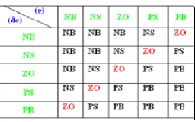
B. Fuzzy Logic Rules:
The objective of this dissertation is to control the output voltage of the boost converter. The error and change of error of the output voltage will be the inputs of fuzzy logic controller. These 2 inputs are divided into five groups; NB: Negative Big, NS: Negative Small, ZO: Zero Area, PS: Positive small and PB: Positive Big and its parameter [10]. These fuzzy control rules for error and change of error can be referred in the table that is shown in Table II as per below:
Table II
VI. SIMULATION OF PROPOSED SYSTEM
Fig.11.Simulink circuit for proposed BLDC drive system
Fig.12.Simulation result for source voltage, source current, dc link voltage, speed of motor, torque of motor and stator current
Vol. 4, Issue 12, December 2015
Fig.14.Source voltage, current, voltage stress and current stress of PFC converter
Fig.15.Simulation result for source voltage, current, dc link voltage, speed , torque and stator current of BLDC motor drive when dc link voltage changes from 100 to 150v
Fig.17. Simulation result for source voltage, current, dc link voltage, speed , torque and stator current of BLDC motor drive during variation supply voltage
Fig.18.THD for source current by using conventional controller
Fig.19.THD for source current by using conventional controller
VII. CONCLUSION
Vol. 4, Issue 12, December 2015
REFERENCES
[1]A PFC-Based BLDC Motor Drive Using a Canonical Switching Cell Converter Vashist Bist, Student Member, IEEE, and Bhim Singh, Fellow, IEEE TRANSACTIONS ON INDUSTRIAL INFORMATICS, VOL. 10, NO. 2, MAY 2014
[2] B. Singh, B. N. Singh, A. Chandra, K. Al-Haddad, A. Pandey, and D.P. Kothari, “A review of single-phase improved power quality ac– dc converters,” IEEE Trans. Ind. Electron.,vol.50,no. 5,pp.962– 981,Oct.2003.
[3] Bhim Singh and Sanjeev Singh,” A Voltage-Controlled PFC Cuk Converter-Based PMBLDCM Drive for Air-Conditioners” in Proc.IEEE Trans. Ind. Appl.,Vol. 48, NO. 2,March/April.2012.
[4] D. S. L. Simonetti, J. Sebastian, F. S. dos Reis, and J. Uceda, “Design criteria for SEPIC and CUK converters as power factor preregulators in discontinuous conduction mode,” in Proc. IEEE Int. Conf. Ind. Electron., Control, Instrum., Autom. (IECON'92), vol. 1, San Diego, CA, USA, 1992, pp. 283–288.
[5] P. Yohan babu, P.Surendra babu, Etal.,, “Power Factor Improvement With High Efficiency Converters”, IOSR Journal of Engineering,Vol. 2(5),May 2012.
[6] T. Gopalarathnam and H. A. Toliyat, “A new topology for Unipolar brushless DC motor drive with high power factor,” IEEE Trans. Power Elect., vol.18, no.6, pp. 1397-1404, Nov. 2003.
[7] P. Alaeinovin and J. Jatskevich, “Filtering of hall-sensor signals for improved operation of brushless dc motors,” IEEE Trans. Energy Convers.,vol. 27, no. 2, pp. 547–549, Jun. 2012.
[8] B. Williams, “Generation and Analysis of Canonical Switching Cell DC to DC Converters,” IEEE Trans. Ind. Electron., vol.61, no.1, pp.329-346, Jan. 2014.
[9] G.R.P.Lakshmi, G.R.Puttalakshmi, S.Paramasivam-Head (R & D), ESAB, Chennai , “Speed Control of Brushless Dc Motor Using Fuzzy Controller,” Indian journal of Applied research .,Vol.3,Issue : 11,Nov 2013.
[10] V. Bist and B. Singh, “An Adjustable Speed PFC Bridgeless BuckBoost Converter Fed BLDC Motor Drive,” IEEE Trans. Ind. Electron., vol.61, no.6, pp.2665-2677, June 2014.
[11] L. Huber, Y. Jang and M.M Jovanovic, “Performance Evaluation of Bridgeless PFC Boost Rectifiers,” IEEE Trans. Power Electron., vol.23,no.3, pp.1381-1390, May 2008.
[12] D. S. L. Simonetti, J. Sebastian and J. Uceda, “The discontinuous conduction mode Sepic and Cuk power actor preregulators: Analysis and design,” IEEE Trans. Ind. Elect., vol. 44, no. 5, pp. 630-637, Oct. 1997.
[13] A. A. Fardoun, E. H. Ismail, A. J. Sabzali, M. A. Al-Saffar, “New Efficient Bridgeless Cuk Rectifiers for PFC Applications,” IEEE Trans.Power Electron., vol.27, no.7, pp.3292-3301, July 2012.
[14] Dichendra Kumar Gonu and Etal., “An Electronic Controlled Adjustable Speed Drive of PMBLDC Motor Using a Single-Stage PFC Half-Bridge Converter,” International Journal of Innovative Research in Science, Engineering and Technology, Vol. 2, Issue 9, September 2013
[15] Bhim Singh, S.S. Murthy.,Etal., “Improved power quality converter fed permanent magnet AC motor for air-conditioning,”., Electric Power Systems Research, December, 2002.,Vol .3Issue : 11,Nov 2013.
[16] V. D. Rajaji, Dr. P. Siddaiah, “Power Factor Correction Using PFC Boost Converter,” International Journal of Engineering Research & Technology, ISSN: 2278-0181, Vol. 2 Issue 4, April – 2013.