Available Online atwww.ijcsmc.com
International Journal of Computer Science and Mobile Computing
A Monthly Journal of Computer Science and Information Technology
ISSN 2320–088X
IMPACT FACTOR: 5.258
IJCSMC, Vol. 5, Issue. 8, August 2016, pg.123 – 130
Modelling and Simulation of Grid Side
Control of DFIG Using Fuzzy and PI
Mallala Harshavardhan
1, K.Rajesh
2PG Student, Dept. Of EEE, Vignan‟s Lara Institute of Technology & Science, Guntur, India 1 Assistant Professor, Dept. Of EEE, Vignan‟s Lara Institute of Technology & Science, Guntur, India 2
Abstract: Now a days wind power energy is playing a major role in power industry. With the raise in application of the wind power variety of topologies are emerging into picture. Within the various types of adjustable speed fixed frequency topologies DFIG is most preferred type because of its efficiency as well as capability to allow wide range of speed variance at simplified converter size. Doubly Fed Induction Generator (DFIG) is actually a wound rotor induction generator which can be implemented to fed electrical power via both stator plus rotor circuit. Stator feeds power straight to grid that is unidirectional. Rotor circuit is linked to a bidirectional ac/dc/ac converter acquiring a common dc link bus. In rotor, power circulation is bidirectional i.e. based on the method of procedure the power flow is whether from rotor side to grid or it may be via grid side to rotor. The main performance of the grid voltage converter is to continue to keep the DC link voltage constant that eventually fed a constant amplitude ac voltage towards rotor side for maintaining the flux constant. With this paper a study and comparison of various control strategies PI, FUZZY of DFIG utilized in a wind power conversion process /generation systems is detailed. In the following paper these two control strategies of grid side is studied and the response regarding each strategy is detailed making use of MATLAB/SIMULINK.
Keywords: Grid Side Converter, DFIG, PI, FUZZY, DC-Link voltage
I. INTRODUCTION
Most Of The Countries In The World Are Now Concentrating On Renewable Energy Sources, In Particularly Wind Energy. Due to its very good characteristics, DFIG is becoming popular wind turbine system, especially for offshore wind farms, [1]-[2].
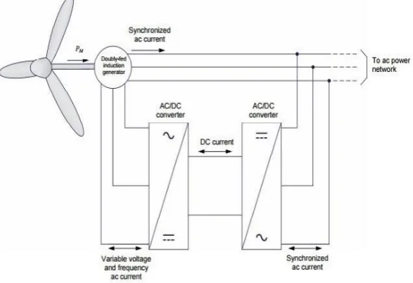
Doubly Fed Induction Generator (DFIG) is basically a wound rotor induction generator with back-to-back converters between the AC grid and the rotor windings Stator feeds power directly to grid which is unidirectional. Rotor circuit is connected to a bidirectional ac/dc/ac converter having a common dc link bus. Together these three components namely the RSC, the DC-link and the GSC form back-to-back converters. The DC-link thus provides the decoupling between the two AC sides, which are at different frequencies. The GSC controls the DC-link voltage.
A vector control scheme for the grid side converter (GSC) gives an independent control of slip active and reactive power exchanged between the grid and the GSC, in order to ensure sinusoidal supply currents and to maintain DC-link voltage constant.
II. MODELINGOFDFIG
The DFIG model adopted in this research paper is the dq0 stationary rotating frame. It is because the model simulation of Doubly Fed Induction Machine (DFIM) is quite suitable with this frame of reference during transients. The transient solution of the DFIM model is possible because of the transformation from abs to dq0 by which the differential equations with time-varying inductances is converted into differential equations with constant inductances, [3]-[4].
Figure 1 Block Diagram of DFIG
The stator circuit equations are given below.
(1)
(2)
Where and are q-axis and d-axis stator flux linkages, respectively.
Converting Eq. (1) and Eq. (2) to d-q frame the following equations can be written as:
Owing to the rotor circuit, if the rotor is blocked or not moving, i.e. , the machine equations can be written in similar way as stator equations:
All the parameters are referred to the primary circuit, which is a stator in this case. Let the rotor rotates at an angular speed , then the d-q axes fixed on the rotor fictitiously will move at a relative speed to the synchronously rotating frame, [5].
The d-q frame rotor equations can be written by replacing in place of as follows:
The flux linkage expressions in terms of current can be written from Fig.3.8 and Fig.3.9 as follows:
It can be connected to the torque as
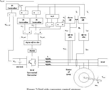
III.GRIDSIDECONVERTERCONTROL
The main aim of the GSC is to maintain the constant DC-link voltage across the common coupling between the back to back converters. To achieve this vector control scheme is used which gives the independent control of active and reactive power flowing between grid and grid side converter. The regulation of the PWM converter is based on the current flowing through it. The direct axis current is used to regulate the DC-link voltage and to regulate the reactive power quadrature axis current is used.
The basic of the vector control is d-q theory or reference frame theory which is used to overcome the problem of time varying parameters with the AC machines, [6].
Essentially by transforming the stator variables to a synchronously rotating reference frame fixed in the rotor. With such transformation (Park„s transformation) all the time varying inductances that occur due to an electric circuit in relative motion and electric circuit with varying magnetic reluctances can be eliminated.
Transformation of three phase stationary to two phase stationary axis is given by
[ ] [
] [ ] (16)
Transformation of two phase stationary axis to two phase synchronously rotating axis is given by
The GSC voltages in its d-q components are obtained by the typical configuration of control strategy is given by
Applying the Laplace transforms to the above two equations
Considering
The angular position of the supply voltage is calculated as
∫ (25)
Where and are the, β (stationary 2-axis) stator voltage components.
The control scheme thus utilizes current control loops for and with the demand being derived from the DC-link voltage error through a standard PI controller. The demand determines the displacement factor on the supply side of the inductor. The plant for the current control loops is given by:
Substituting (23),(24) in (21),(22) respectively, and being the reference for the voltages values and can be obtained by:
The value of and are considered to be the reference input values to the PWM converter by which level
Figure 2 Grid side converter control strategy
IV.PICONTROLLERBASEDDFIG
Proportional Integral controller based technique is the traditional method used to regulate the DC –link voltage. These control techniques are used to achieve better dynamic control of DFIG. This control technique having the advantages of [6]
1. Constant DC-link voltage in case of a wind park or wind turbine.
2. When wind speed is very high restricted generation of active power is allowed.
3. Maintenance cost is minimized and also exploration in case of wind park or wind turbine.
V. DESIGNOFFUZZYCONTROLLER
Proportional integral control technique is commonly using traditional control technique but the performance of the PI controller is mainly based on a suitable choice of the PI gains. Tuning of PI gains becomes the most difficult task. To overcome this problem a robust controller is needed. Fuzzy is one of these control technique which is robust about to many non linear procedures, [7].
Fuzzy controller uses a systematic method to control a nonlinear procedure based on human experience. This is defined as heuristic method this can enhance the operation of closed loop system. The operation of the fuzzy controller is based on its capability to simulate several role implications at the same time procedure, and it results the significantly comprehensive output.
A well designed fuzzy controller can provide enhanced operation in presence of variations in parameters, external perturbations, and load existence than conventional PI controllers. The design of fuzzy controller mainly consists of four building blocks: fuzzification block, fuzzy knowledge based block, fuzzy inference engine and defuzzification block. The conversion of the classical set to the fuzzy set is called the fuzzification. Triangular fuzzifier is used among different fuzzifiers such as triangular, trapezoidal, singleton and Gaussian. By assigning some membership function to each and every input with the help of the fuzzifier is convert input into fuzzy set, [8]-[9].
Table 1.The Fuzzy rule base e
NL NM NS ZE PS PM PL
NL NL NL NL NL NM NS NL
NM NL NL NL NM NS ZE NM
NS NL NL NM NS ZE PS NS
ZE NL NM NS ZE PS PM EZ
PS NM NS ZE PS PM PL PS
PM NS ZE PS PM PL PL PM
PL ZE PS PM PL PL PL PL
The fuzzy sets have been determined as: NL, negative large, NM, negative medium, NS, negative small and ZE, zero, PS, Positive small, PM, positive medium, PL, positive large, respectively
Figure 3Triangular membership functions for input, change in error and output fuzzy sets of the fuzzy controller.
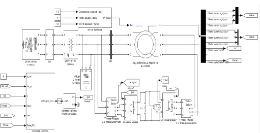
VI.SIMULATIONDIAGRAMS
A wind power generation system based on doubly fed induction generator (DFIG) connected to grid system with PI and Fuzzy control system is simulated using MATLAB\SIMULINK software. The frequency is set to 50Hz. At 0.01sec the reference DC Link voltage is 700V and from 0.4sec the DC Link voltage 1200V. The Figure 4 shows the simulation of DFIG in which stator is connected to the grid and rotor connected to the grid by the back to back PWM converters.
VII. SIMULATIONRESULTS
The GSC control strategy using PI and Fuzzy logic is implemented for DFIG using MATLAB/SIMULINK and results are presented in this section. The performance of the PI and Fuzzy logic controllers is analyzed by using FFT analysis. The main objective of the GSC is to main DC-Link voltage constant. At 0.01sec the reference DC Link voltage is 700V and from 0.4sec the DC Link voltage 1200V. The DC-link voltage using PI and Fuzzy logic controller are shown in figures.
Figure 5 DC-Link voltages across capacitor using PI controller
Figure 5 shows the DC-Link voltage using PI controller. In the waveform voltage matches to the reference voltage. Settling time is less than 0.1 sec. But analysing the waveform it contains more ripple content which disturbances the performance. From figure 6 DC-Link voltage using fuzzy controller is analysed. Fuzzy logic controllers enhance the performance and profile of the DC-Link voltage and also ripple content is reduced.
Figure 6 DC-Link voltage using Fuzzy controller
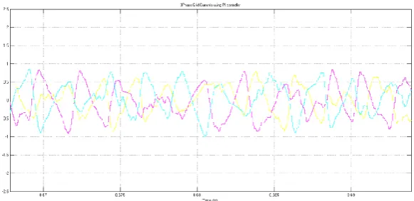
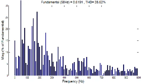
Figure 8 FFT Analysis of Grid currents using PI controller
Figure9 3Phase Grid currents using Fuzzy logic controller
Figure 10 FFT Analysis of Grid currents using Fuzzy controller
CONCLUSION
The fuzzy control applied to DFIG is researched, on the basis of which the simulation study is made on Grid side control of DFIG wind generation system. The comparative study is made between PI controller and fuzzy controller in DFIG wind power generation system. By using PI controller DC-Link voltage and grid currents of DFIG are analyzed. While fuzzy controller has strong robustness to control system whose parameters varied. The results show that fuzzy controller has better performance than PI controller in terms of THD value.
R
EFERENCES[1] J. F. Walker, N. Jenkins, “Wind Energy Technology”, John Wiley & Sons, Ltd, 1997. [2] T. Ackermann, "Wind Power in Power Systems", John Wiley & Sons, Ltd, England, 2005
[3] A. Tapia, G. Tapia, J. X. Ostolaza, J. R. Saenz, R. Criado, J. L. Berasategui, "Reactive power control of a wind farm made up with doubly fed induction generators”, (I) and (II), IEEE PortoPower Tech Conference, 2001.
[4] J. L. Rodríguez-Amenedo, S. Arnalte, J. C. Burgos, “Automatic generation control of a wind farm with variable speed wind turbines”, IEEE Transactions on Energy Conversion, vol. 17, no 2, pp. 279-284, 2002.
[5] Satish Choudhury, Kanungo Barada Mohanty, B.Chitti Babu, ―Performance Analysis of Doubly-Fed Induction Generator for Wind Energy Conversion System‖, Proc. PSU- UNS International Conference on Engineering and Technology (ICET-2011), Phuket, Thailand, pp.532-536, May 2011.
[7] Xu L, Wang Y. “Dynamic modeling and control of DFIG -based wind turbines under unbalanced network conditions” (J). IEEE Transactions on Power Systems, 22( I): 314-323. 2007.
[8] Hee-Sang Ko, Gi-Gab Yoon and Nam-Ho Kyung (2009) “Variable speed DFIG wind energy system for power generation and harmonic current mitigation” Renewable Energy 34 1545–155, 2009.
[9] Jingjing Zhao, Xin Li ,JutaoHao and Jiping Lu “Reactive power control of wind farm made up with doubly fed induction generators in distribution system” Electric Power Systems Research 80 698–706 , 2010.
[10] S. Muller, M. Deicke and Rik W. De Doncker, “Doubly fed induction generator systems for wind turbines”, IEEE Industry Applications Magazine, Vol. 8, No.3, pp. 26-33, May/June 2002.
[11] G.B. Chung and J.H Choi, “Application of fuzzy PI control algorithm as stator power controller of double – fed induction machine in wind power generation systems,” J. Power Electron., vol 9, no. 5, pp. 677 – 685, Sep. 2009.
[12] Yazhou Lei; Mullane, A.; Lightbody, G.; Yacamini, R., "Modeling of the wind turbine with a doubly fed induction generator for grid integration studies," Energy Conversion, IEEE Transactions on, vol.21, no.1, pp.257 – 264, March 2006.
BIOGRAPHY
M.Harshavardhan received the B.Tech. degree in Electrical and Electronics Engineering from NRI Institute of Technology, perecharla, India, in 2013, and currently, pursuing M. Tech. Degree in Power Electronics and Electrical Drives from VLITS, Vadlamudi. His research interest includes Electrical drives, Solar Photovoltaic grid connection and renewable energy sources. [email protected]