Study of smart antenna wide band multi beam by
algorithm switch beam
Yuliarman Saragih
1, Ibrahim2, Agatha Elisabet3
Department of Electric Engineering, Engineering Faculty of Singaperbangsa Karawang of University, Jl. HS.Ronggo Waluyo, Puseurjaya, Kec. Telukjambe Timur., Kabupaten Karawang, Jawa Barat 41361, Indonesia
E-mail : 1 [email protected], 2 [email protected],
Abstract. The use of wideband antennas in radio frequency (RF) systems are intended to improve the efficiency of the system economically. So that problems arise due to differences in RF system frequency allocation in each country can be overcome. Other than that, the need for an antenna that can optimize the direction of the beam becomes one which became a consideration, for that to develop a smart antenna that is capable of producing the different beam. In various studies, wideband antennas have been built only able to work on a single beam. Meanwhile, the antenna has also been proven to be working in multi-beam but still works on a single frequency. The researcher intends to develop an antenna that can work as a smart antenna that applies multi-beam with switching algorithms by having a wide working frequency (wideband). Multi-beam with wideband can be produced by combining wideband antenna array with a Butler matrix that applies the switching beam algorithm with phase array technique so that it can be a smart antenna because the antenna can be adjusted of the beam as desired.
1. Introduction
In the current convergence era, customer premise eqiupments (CPEs) are needed that are able to work wideband, so that the various systems can be integrated. The use of wideband antennas on a radio frequency (RF) system is intended to improve the efficiency of the system economically. So the problems that arise due to differences in RF system frequency allocation in each country can be overcome. In addition, antenna needs that have the ability to optimize beam direction are one of the considerations, for which smart antennas are developed which are capable of producing different beams.
2. Objective and scope of study
Journal of Sustainable Engineering: Proceedings Series 1(2) 2019 doi:10.35793/joseps.v1i2.37
This paper and its contents may be used under the terms ofCreative Commons Attribution 4.0license. Any further
Objective and scope of study focus on a smart array that adjusts beam to the environment (needs), and is divided into two classifications, namely:
a. Phased array or multibeam antenna Phase Array or multibeam antenna consists of several fix beams that have a certain direction and can be selected whichever will be activated
b. Adaptive antenna array Adaptive antenna array is an antenna array that can receive signals simultaneously to be combined which can maximize the value of the signal to interference and noise ratio (SINR). This means that the antenna main lobe is always in the main beam. It will be more clearly (shown figure 1).
Figure 1Smart Antenna Definitions
There are two classifications in general, including Switched beam antenna systems and adaptive antenna arrays such as:
a. Switched beam antenna system Switched beam antenna system consists of several fix beams that have certain mainlobe in each direction. This antenna system detects signal strength from all beams and then selects one direction beam that has the highest signal strength.
b. Adaptive antenna array Adaptive antenna array is the most advanced antenna, where the antenna uses severalvariations of the adaptive algorithm to get the highest SINR with the lowest interference.
Figure 2
Switched beam antenna system and adaptive antenna array
3. Literature review
Various studies have been conducted to design wideband antennas, as in the study [6] Konda, R.B. Pushpanjali, G.M. Mulgi, S.N. Satnoor, S.K. Hunagund, P.V. "Microstrip array antenna for wideband operation". International Conference on Advances in Microwave Theory and Applications.pp: 511-513. 2008. It is proposed to use the wideband array technique with the method of mutual coupling. The designed antenna must also answer the need for increased capacity with a wider coverage. Therefore a smart antenna was developed as proposed [8] Bellofiore, S. Foutz, J. Balanis, C.A. Spanias, A. "Smart antennas for wireless communications" Antennas and Propagation Society International Symposium. Vol.4. PP: 26-29. 2001. The main key to smart antenna is the direction of the beamwidth, for conventional beam direction, a mechanical motor can be adjusted using an algorithm such as R. 9 Mailloux, Phased Array Antenna Handbook, 2nd ed. Norwood, MA: Artech House, 2005. While at this time it is known that more phase arrays and butler matrices are used. Base on [10] Hubregt J. Visser, Array and Phased Array Antenna Basics, John Wiley & Sons Ltd.2005. Because the change in the input signal phase can change the beamwidth of the antenna. Some of antenna designs that useof beam switching techniques have been carried out in the journal [14] by Jae Hee Kim, Wee Sang Park. "Sectoral Conical Beam Former for a 2 x 2 IEEE Antennas Array and Wireless Propagation Letters, Vol: 8, pp (s): 712 - 715. 2009. Where in the journal use a 4 x 4 butler matrix as a feeder on the antenna array which is capable of producing phase array antennas with a variety of different beams. In the journal [6] wideband antennas have been proven that can only work on a single beam. So far and or, until now there has been no research on smart antennas that are able to apply multibeam with switching algorithms and have a wide working frequency (wideband). The results obtained are then expected to be able to add knowledge, especially in the field of smart antennas.
4. Methodology
The method used to produce a smart antenna is divided into two, the adaptive algorithm method and the beamforming method. Adaptive algorithm method is a method that is able to produce an adaptive algorithm so that the signal received by the antenna has a high power with low interference. Meanwhile, the beamforming method is a method used to make multiple radiation patterns (multiple) from the antenna array by adding a phase change construction to the antenna array.
The factor array equation (AF) in the array antenna satisfies equation 1.1, namely:
' ˆ ( ) 1 1 ( , ) mn mn N M j r mn n m r AF
I
e
Where :From equation 1.1, it can be seen that:
β
= propagation constanta,I
nm = Magnitude.α
= phase.Although AF is not a true radiation pattern, AF plays an important role in the form of
a radiation pattern. So that indirectly the radiation pattern of dabat changes with
changing phase (α), and this is in accordance with equation 1.1. From this analysis it
was found the results of the antenna beam changes by changing the value of α. This
change in α value can occur if we add a matrix butler to the antenna.
5. Experimental works
5.1 Focus on Achievement
The focus of the problems raised in this antenna research have not been produced antennas that are capable of working at wide frequencies with diverse radiation (beam) patterns.
5.2. Research Purposes
Seeing the focus of the problem raised, the purpose of this study is to produce smart antennas that are capable of applying multibeam with a switching algorithm by having a wideband. 5.3. Ultimate Renewal (Propose)
The author proposes the main renewal of combining wideband antenna with butler matrix which applies the swiching beam algorithm so that it can be a smart antenna because it can adjust the beam as desired with a wide working frequency (wideband).
5.4. Research Hypothesis (Propose)
The author has proven by simulation using ADS, and produces an antenna that is capable of multi beam but still works on a single frequency. Then proceed with a second simulation that is capable of producing antennas that work on dual-frequency and multibeam. For this reason, the authors propose a hypothesis in the form of: Multibeam with a wideband working frequency can be produced by combining a wideband antenna with a butler matrix that applies the swiching-beam algorithm with phase array techniques so that it can be a smart antenna because it can adjust the beam as desired. The research position of the author with the various references available is more complete in Table 5.1:
Table 1 Preliminary Test Results
No. Ref. Single Patch Antenna Array Single Feed Multi Feed Phase Array Dual Band Multi Band Multi Beam 1 [1] yes - yes - - - yes - 2 [2] yes - yes - - - yes - 3 [3] yes - yes - - - yes - 4 [4] yes - yes - - - yes - 5 [5] yes - yes - - - yes -
6 [6] - yes yes - - - yes -
7 [7] - yes yes - - - yes -
8 [13] - yes - yes yes - - yes
9 [14] - yes - yes yes - - yes 10 [15] - yes - yes yes - - yes 11 [16] yes - - yes - - - yes 12 [17] yes - - yes - - - yes
13 [18] yes - - yes - yes - yes
14 Reaearch
Position - yes - yes yes - Yes Yes
In Table 1, it can be seen that there has never been a research (going there) multibeam
wideband antenna. While the focus and explanation of the research is seen in the next
section
5.5. Analysis of the Switching Beam Algorithm approach
In this subab is explained the switching beam algorithm. The author makes the area
based on the antenna's working direction and the power received, where the minimum
power is -96dBm and if it is smaller, it is considered an interferer shown figure 3.
As shown figure 3, A from Beam 1 will run to beam 2.
Figure 3Algoritma Switching Beam
The following below is the algorithm shown figure 4
Figure 4 Direction of Beam Algorithm
5.6
Antenna Design Algorithm
Antenna design as shown figure 5:
Figure 5Antenna Design Structure
5.7. Geometric Form
Geometrically of designed, the antenna to be built as shown figure 6.
Figure 6 The shape of the antenna geometry designed
5.8. PRERESULT Designing
The design consists of 2 Main Parts namely Butler Matrix and Antenna Array, this circuit which is simulated using Advance Design System (ADS) Software:
5.8.1. Microstrip antenna
In the first setup, the design of a single-patch microstrip antenna was carried out. In designing this single patch antenna is shown figure 6. When integrated all the components of the butler matrix, a layout image will appear as in Figure 7. That is a 4 X 4 butler matrix with input ports and 4 output ports. Complete Image of Butler Matrix shown figure 7. The simulation results are shown figure 8.
Figure 7 Real of Butler Matrix
Figure 8 Result of Phase Power Simulation from Butler Matrikx
When integrated with the antenna, the Butler Matrix and Antenna Array images are shown figure 9.
Figure 9 Butler Matrix Simulation with Antenna Array
A. Simulation results if supplied in Port 1 B. Simulation result if supplied in Port 2.
Figure 10Supply Results Port 1 Figure 11 Supply Result Port 2
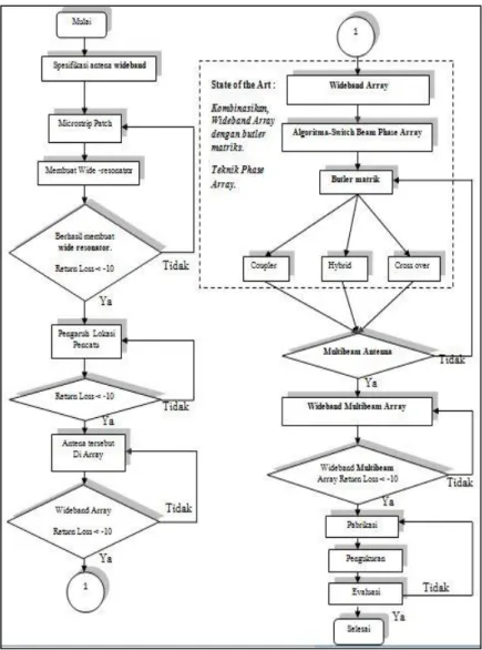
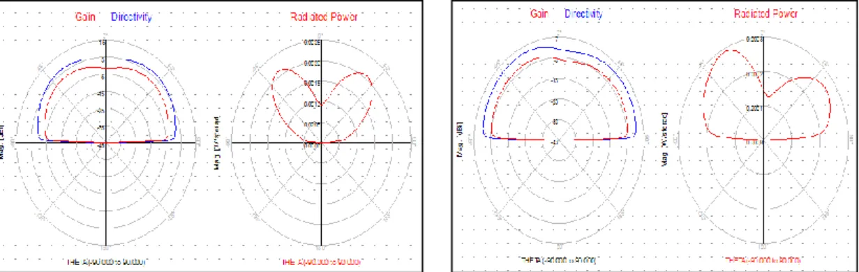
In Figure 10 Shown of the results of the supply on port 1. Where is the direction of the beam directed to 0 degree. In Figure 11 Shown the results of the supply on port 1. Where is the direction of the beam directed at 15 degree.
C. Simulation Results if supplied in Port 3
Figure 12 Supply Results Port 3
In figure 12 shown results of the supply on port 3. Where are the direction of the beam directed to -15 degrees.By the results of the temporary simulation Antenna has been produced that is able to work as multi beam by using the butler matrix. Further research focuses on producing antennas and matrix butlers capable of working on wideband, not just single bands. 5.9. PRERESULT Design 2
The design consists of 2 Main Parts namely Butler Matrix and Array Antenna, this circuit which is simulated using Advance Design System (ADS) Software:
5.9.1. Dual-Band Microstrip Antenna
In the first design, a single-patch microstrip antenna was designed to produce Dual-band. In designing this single patch antenna is shown figure 13.
Figure 13. Antenna Single-Patch Microstrip Dual-band
While the simulation results are shown figure 5.12. Where is the antenna works at frequencies of 2.205 GHz and 2.65 GHz. The antenna can work on dual-frequency, for the next stage of research, which is to make the antenna work wideband. (This is being done).
Figure 14S11 results from a Dual-Band Microstrip Single-Patch Antenna
When integrated with the antenna, the Butler Matrix and Antenna Array images are shown figure 15.
Figure 15Butler matrix simulated using of Antenna Array
A. Simulation Results if supplied in Port 1 B. Simulation Results if supplied in Port 2.
Figure 16Supply Results Port 1 Figure 17Supply Results Port 2
In figure 16 shows the results of the supply on port 1. Where is the direction of the beam that directed at -40 degrees and 40 degrees.Figure 17 shown of the results of the supply on port-2. Where is the direction of the beam that directed at -25 degrees and 25 degrees.
C. Simulation Results if supplied in Port 3 D. Simulation Results if supplied in Port 4
Figure 18Supply Results Port 3 Figure 19Supply Results Port 4
Figure 18 has shown the results of the supply on port 3. Where is the direction of beam that to directed at -15 degrees. Base on the simulation results, Antennas are able to work with dual-band multi beam by using the butler matrix. Subsequent research focuses on producing antennas and butler matrices that are capable of working on wideband, not just single bands or dual bands.
6. CONCLUSION
The use of wideband and multibeam antennas will be a future requirement. In various studies wideband antennas have been produced which are only capable of working on a single beam. Meanwhile, it has also been proven that antennas are expected to work multi beam but are still working on a single frequency. The researcher intends to develop the research. The results of the antenna studied will be able to work as smart antennas capable of applying multibeam with a switching algorithm by having a wideband working frequency of shown figure 20. Multibeam with a wideband working frequency can be produced by combining a wideband antenna with a butler matrix that applies the swiching-beam algorithm with phase array techniques so that it can be a smart antenna of shown figure 21 because it can adjust the beam as desired.
Figure 20Final Result of Smart Antenna Figure 21 Final Prototype of Smart Antenna
7. References
[1] Ya-Chung Yu and Jenn-Hwan Tarng, “A Novel Modified Wideband Planar Inverted-F Antenna” IEEE Antennas And Wireless Propagation Letters, vol.8, pp 189-192. April.2009
[2] Keon-Myung Lee, Young-Je Sung, Jung-Woo Baik, Young-Sik Kim, “A triangular microstrip patch antenna for multi-band applications” Microwave Conference, 2008. APMC 2008. Asia-Pacific. pp 1 – 4. 2008
[3] Romeu, J. Soler, J “Generalized Sierpinski fractal wideband antenna” IEEE Transactions on Antennas and Propagation. vol. 49 pp. 1237 – 1239. 2001
[4] Manoj, J. Rohith, K.R. Binu, P. Mohanan. “Compact planar wideband antenna” Antennas and Propagation Society International Symposium. vol. 1B . pp : 471 – 474. 2005 [5] Kin-Lu Wong. Gwo-Yun Lee. Tzung-Wern Chiou. “A low-profile planar monopole
antenna for wideband operation of mobile handsets” IEEE Transactions on Antennas and Propagation. vol. 51 pp 121 – 125. 2003
[6] Konda, R.B. Pushpanjali, G.M. Mulgi, S.N. Satnoor, S.K. Hunagund, P.V. “Microstrip array antenna for wideband operation”. International Conference on Advances in Microwave Theory and Applications. pp :511-513. 2008
[7] Lima, A.G.M. de Menezes, L.R.A.X. “A wideband fractal antenna array to software defined radio” International Conference on Microwave and Optoelectronics. pp ; 256-258. 2005
[8] Bellofiore, S. Foutz, J. Balanis, C.A. Spanias, A. “Smart antennas for wireless communications”. Antennas and Propagation Society International Symposium. Vol. 4. Pp : 26-29. 2001
[9] R J Mailloux, Phased Array Antenna Handbook, 2nd ed. Norwood, MA: Artech House, 2005
[10] Hubregt J. Visser, Array and Phased Array Antenna Basics. John Wiley & Sons Ltd. 2005
[11] Donghee Shim, Seungwon Choi. “Should the smart antenna be a tracking beam array or switching beam array?” Vehicular Technology Conference. pp: 494 - 498 vol.1.1998 [12] Chia-Chan Chang; Ruey-Hsuan Lee; Ting-Yen Shih. “Design of a Beam
Switching/Steering Butler Matrix for Phased Array System” IEEE Transactions on Antennas and Propagation. Volume: 58 , Issue: 2. Page(s): 367 - 374. 2010
[13] Ming-Iu Lai, Tjung-Yu Wu, Jung-Chin Hsieh, Chun-Hsiung Wang, Shyh-Kang Jeng. “A miniature, planar, and switched-beam smart antenna employing a four- element slot antenna array for Digital Home applications” IEEE Antennas and Propagation Society International Symposium. Page(s): 3376 - 3379 . 2007
[14] Kornek, D. Orlob, C. Rolfes, I “A Sierpinski shaped patch antenna for beam switching” IEEE Antennas and Propagation Society International Symposium. Page(s): 1 – 4. 2009
[15] Sooksumrarn, P. Krairiksh, M. ” A Dual-Band Dual-Feed Switched-Beam Single Patch Antenna”. Asia-Pacific Microwave Conference APMC. Pp:1-4.2007.