Selection of our books indexed in the Book Citation Index in Web of Science™ Core Collection (BKCI)
Interested in publishing with us?
Contact [email protected]
Numbers displayed above are based on latest data collected.For more information visit www.intechopen.com Open access books available
Countries delivered to Contributors from top 500 universities
International authors and editors
Our authors are among the
most cited scientists
Downloads
We are IntechOpen,
the world’s leading publisher of
Open Access books
Built by scientists, for scientists
12.2%
116,000
120M
TOP 1%
154
Online Mapping-Based Navigation System for Wheeled
Mobile Robot in Road Following and Roundabout
Mohammed A. H. Ali and Musa Mailah
Additional information is available at the end of the chapterAbstract
A road mapping and feature extraction for mobile robot navigation in road roundabout and road following environments is presented in this chapter. In this work, the online mapping of mobile robot employing the utilization of sensor fusion technique is used to extract the road characteristics that will be used with path planning algorithm to enable the robot to move from a certain start position to predetermined goal, such as road curbs, road borders, and roundabout. The sensor fusion is performed using many sensors, namely, laser range finder, camera, and odometry, which are combined on a new wheeled mobile robot prototype to determine the best optimum path of the robot and localize it within its environments. The local maps are developed using an image’s preprocessing and processing algorithms and an artificial threshold of LRF signal processing to recog-nize the road environment parameters such as road curbs, width, and roundabout. The path planning in the road environments is accomplished using a novel approach so called Laser Simulator to find the trajectory in the local maps developed by sensor fusion. Results show the capability of the wheeled mobile robot to effectively recognize the road environments, build a local mapping, and find the path in both road following and roundabout.
Keywords:LRF, vision system, odometry, laser simulator, road roundabout, road following, 2D map, local map
1. Introduction
Autonomous navigation can be defined as the ability of the mobile robot to determine its position within the reference frame environment using suitable sensors, plan its path mission through the terrain from the start toward the goal position using high planner techniques and
© 2018 The Author(s). Licensee IntechOpen. This chapter is distributed under the terms of the Creative Commons Attribution License (http://creativecommons.org/licenses/by/3.0), which permits unrestricted use, distribution, and reproduction in any medium, provided the original work is properly cited.
perform the path using actuators, all with a high degree of autonomy. In other words, the robot during navigation must be able to answer the following questions [1]:
• Where have I been? It is solved using cognitive maps. • Where am I? It is determined by the localization algorithm. • Where am I going? It is done by path planning.
• How can I go there? It is performed by motion control system.
Autonomous navigation comprises many tasks between the sensing and actuating processes that can be further divided into two approaches: behavior-based navigation and model-based navi-gation. The behavior-based navigation depends on the interaction of some asynchronous sets of behaviors of the robot and the environment such as: build maps, explore, avoid obstacles, and follow right/left and goal seeking, which are fused together to generate suitable actions for the actuators. The model-based navigation includes four subtasks that are performed synchronously step by step: perception, localization, path planning, and motion control. This is the common navigation systems that have been used and found in the literature.
The model-based navigation will be explained in details, since it is implemented in the proposed navigation system. In the perception task of this navigation model, the sensors are used to acquire and produce enormous information and good observation for the environments, where the robot navigates. There is a range of sensors that can be chosen for the autonomous navigation depending on the task of mobile robot, which generally can be classified into two groups: absolute position measurements and relative position measurements [2]. The European robotics platform (EUROP) marks the perception process in the robotics system as the main problem which needs further research solutions [1].
The localization process can be perceived as the answer to the question: where am I? In order to enable the robot to find its location within the environments, two types of information are needed. First, a-priori information is given to the robot from maps or cause-effect relationships in an initialization phase. Second, the robot acquires information about the environment through observation by sensors. Sensor fusion techniques are always used to combine the initial information and position measurements of sensors to estimate the location of the robot instantly [1].
In the path planning process, the collision-free path between start and target positions is determined continuously. There are two types of path planning: (a) global planning or delib-erative technique and (b) local path planning or sensor-based planning. In the former, the surrounding terrain of the mobile robot is known totally, and then the collision-free path is determined offline, while in the latter, the surrounding terrain of the mobile robot is partially or totally unknown, and the robot uses the sensor data for planning the path online in the environments [1]. The path planning consists of three main steps, namely, the environment’s modeling, determination of the collision-free trajectory from the initial to target positions, and searching continuously for the goal [1].
In motion control, the mobile robot should apply a steering strategy that attempts to prevent slippage and reduce position errors. The control algorithm has to guarantee a zero steady-state
orientation or position error. The kinematic and dynamic analysis of the mobile robot is used to find the parameters of the controllers for continuously avoiding the obstacles and moving toward the target position through the predefined path [1]. The autonomous navigation system can be classified according to the environmental features as follows:
i. Structured environments: it is usually found in indoor applications, where the environ-ments are totally known.
ii. Semi-structured environments: the environments are partially known.
iii. Unstructured environments: outdoor applications are almost unstructured, where the environments are totally unknown.
There are many factors that can make outdoor autonomous navigation very complex in comparison to the indoor navigation:
i. The borders of surrounding terrain in the indoor application are clear and distinct. However, in contrary to that, they are mostly“faded”in outdoor setting.
ii. The robot algorithm should be able to discover and deal with many things that are not in the initial planning.
iii. The locomotion of robot will be different depending on the terrain roughness.
iv. Outdoor autonomous navigation should have adequate robustness and reliable enough because the robot typically works and meddles with people and encounters unexpected moving obstacles.
v. Weather changes can affect the mobile robot sensor measurement, electronic devices, and actuators. For example, the inhomogeneous of the light will affect the camera when capturing the image of the scene, the sunray affects the laser measurement, and ultrasonic measurement becomes unavailable.
Although the outdoor navigation in urban area is a topic involving a wide range and level of difficulties, it is attractive and forms a challenge to the researchers who are motivated to discover solution(s) to the problems via their proposed developed technique. Until today, there is as yet a robot or vehicle, which is able to drive fully autonomously on the roads of urban buildings, taking into account a high level of robust interaction with its environments [3, 4]. This vehicle is expected to operate in a dangerous situation, since it always passes through crowded area, must follow printed or signal traffic lights and more often than not, it is in touch with the people.
Most navigation systems on the roads are performed using two or more sensors to obtain the parameters of the surrounding environment, taking into consideration various situations and conditions. Sensor fusion technique is the common method that has been used in navigation of mobile robot in road environments. In this model, the methods for extracting the features of roads can be done with reference to either behavior-based navigation or model-based naviga-tion as described in the following paragraphs.
Global positioning system (GPS) is used as the main sensor and combined with odometry and LRF for trajectory tracking, obstacle avoiding and localization in curbed roads [5] or navigating
mobile robot between urban buildings [6]. GPS can be combined with LRF and dead reckoning for navigating vehicles in roads using beacons and landmarks [7], combined with camera vision for localizing mobile robot in color marked roads [8], combined with 3D laser scanner for building compact maps to be used in a miscellaneous navigation applications of mobile robot [9], combined with IMU, camera vision, and sonar altimeter for navigating unmanned helicopter through urban building [10] or combined with LRF and inertial sensors for leading mobile robot ATRV-JR in paved and rugged terrain [11, 12]. GPS can be combined with INS and odometry sensor for helping GPS to increase its positioning accuracy of vehicles [13]. GPS is combined with odometry and GIS (geographical information system) for road matching-based vehicle naviga-tion [14]. GPS can also be combined with LIDAR (light detecnaviga-tion and ranging) and INS for leading wheelchair in urban building by 3D map-based navigation [15]. GPS is combined with a video camera and INS for navigating the vehicles by lane detection of roads [16]. GPS is combined with INS for increasing position estimation of vehicles [17]. GPS is combined with INS and odometry for localizing mobile robot in urban buildings [18]. Camera video with odometry is used for navigating land vehicle, road following by lane signs and obstacles avoiding [19]. Omni-directional infrared vision system can be used for localizing patrol mobile robot in an electrical station environment [20]. 3D map building and urban scenes are used in mobile robot navigation by fusing stereo vision and LRF [21].
LRF can be combined with cameras and odometry for online modeling of road boundary navigation [6], for enhancing position accuracy during mobile robot navigation [22] or for correcting trajectory navigation of mobile robot [23]. Also, it can be combined with compass and odometry for building map-based mobile robot navigation [1]. It can be combined with color CCD camera for modeling roads and driving mobile robot in paved and unpaved road [24], for crossing roads through landmark detection [25], for obstacle detecting and avoiding [26] or for road recognition process [27]. It can be combined with sonar and camera vision for navigating mobile robot when crossing roads [1]. 3D LRF is combined with two color camera, INS, and odometry for cross-country navigation of ADAM mobile robot through natural terrain [1]. It can be combined with IMU, CCD camera, and odometry for guiding tractor vehicle in Citrus Grove [1]. It can be combined with camera, LRF, sonar, and compass for building 3D map of an urban environment [1].
Priori map can be used for navigation by mapping precisely environment landmarks [1]. Dead reckoning is used for estimating position accurately by feature detection in mobile robot [1]. A hybrid methodology between the teleoperating and autonomous navigation system has been applied in a curbed road environment as explained in [5]. A combination of differential global positioning system (DGPS) and odometry with extended Kalman filter is used to localize the
mobile robot in a road environment. LRF is used for obstacle avoidance by finding the suitable path to pass through the road curbs and to estimate the position of the road curbs during trajectory tracking. The main setback in this work is that the robot cannot work autonomously in road environments.
Jose et al. [7] presented a robust outdoor navigation system using LRF, and dead reckoning is proposed for navigating vehicles using beacons and landmarks on the roads. The system is studied considering several cylindrical or V-shaped objects (beacons) that can be detected
using LRF in a road environment. The information filter (derived fromKalmanfilter) is used to gather data from sensors and build map and determine the localization of robot. The results show that the accuracy of the online mapping is very close to DGPS, which has accuracy equal to 1 cm. Donghoon et al. [8] proposed a navigation system method based on fusing two localization systems is proposed. The first one uses a camera vision system with particle filter, while the second uses two GPS withKalmanfilter. The printed marks on the road like arrows, lines, and cross are effectively detected through the camera system. By processing the camera’s data using the hyperbola-pair lane detection, that is,Delaunaytriangulation method for point extraction and mapping based on sky view of points, the robot is able to determine the current position within its environment. To eliminate the camera drawback like lens distortion and inaccuracy in the long run, GPS system data are used to complement and validate the camera’s data. The errors between the predefined map and real-time measurements are found to be 0.78 m inxdirection and 0.43 m inydirection.
Cristina et al. [9] suggested a compact 3D map building for a miscellaneous navigation applica-tion of mobile robot in real time performed through the use of the GPS and 3D laser scanner. A 3D laser scanner senses the environment surface with sufficient accuracy to obtain a map, which is processed to get a qualitative description of the traversable environment cell. The 3D local map is built using 2DVoronoidiagram model, while the third dimension is determined through the data from laser scanner for the terrain reversibility. The previous map is gathered with the GPS information to build a global map. This system is able to detect the slopes of navigated surfaces usingBrezets algorithm and the roughness of the terrain using normal vector deviation for the whole region. Although the proposed algorithm is very complicated, the result shows that it is able to extract an area as big as 4020 m in an outdoor environment for 0.89 s.
2. Platform overview
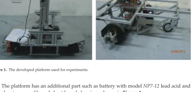
A new platform for an autonomous wheeled mobile robot navigation system has been designed and developed in our labs. It is comprised of the following parts as shown in Figure 1:
• Two motors, type: DC-brush with power120 Wand model DKM.
• One spherical Castor wheel.
• 4 m range LRF; modelHOKUYO URG-04LX-UG01.
• High resolution WiFi camera, modelJVC-GC-XA1B.
• Two optical rotary odometry; model,B106.
• Motors drivers, typesSmartDrive 40.
• Five cards for the interface free-based controllers system (IFC): interface power,
abbrevi-ated asIFC-IP00;interface computer, abbreviated asIFC-IC00; interface brushless, abbre-viated asIFC-BL02; and interface brush motors, abbreviated asIFCBH02.
• The platform has an additional part such as battery with modelNP7-12lead acid and the
aluminum profile and sheet-based chassis as shown inFigure 1.
3. Sensor modeling and feature extraction
The data coming from each sensor in the platform were prepared in such a way that it enables for the extraction of the road features autonomously while navigating on the road. It is described in the following section.
3.1. Camera
JVC-GC-XA1Bcamera is utilized to figure out the environments in front of the robot with good resolution (760320) and speed equal to 30 frame/s. The sequences of pictures are extracted
from the live video using image processing tool boxes in MATLAB. An algorithm has been developed that can take the image sequences from the video and apply multiple operations to get a local map from the image and perform further calculation for road following and roundabout detection. In general, the image sequences processing algorithm consists of three main parts:
i. Preprocessing of the image for depth processing.
ii. Processing of the image and development of the environment local map.
iii. Post processing algorithms to perform the following subtasks:
• Roundabout detection based on LS approach. • Road following in the roads without curbs.
The first and second steps will be explained here, while the third one will be explained in next section.
(i) Preprocessing of the image for depth processing.
A preprocessing algorithm is utilized to capture the environments of the road from the live video and prepare it in an appropriate form to be processed in the next processes. The main operations that have been used at this step can be briefly described as follows:
• Constructing the video input object: the video input object represents the connection
between MATLAB and a particular image acquisition device. vid = videoinput(‘winvideo’,3);
• Preview of the WiFi video: it creates a video preview window that displays live video data
for video input object. The window also displays the timestamp and video resolution of each frame and the current status of video input object.
preview (vid);
• Setting the brightness of live video
The brightness of image’s sequences is adjusted, since the aperture of camera is not automatic. Following command is used:
set (vid.source,‘Brightness’, 35);
• Start acquiring frames
This function helps to reserve the image device for the exclusive use in this program and locks the configuration to others applications. Thus, certain properties become read only while running.
Start(vid);
• Acquiring the image frames to MATLAB workspace
It returns the data, which contains the number of frames specified in the (Frames per Trigger) property of the video input object.
data = getdata(vid);
• Crop image
It allows for cutting the interesting regions in the images. In the proposed algorithm, the bottom half of the image is cropped, since it contains the nearest area of the road to the robot; also to save time needed for calculation in comparison with whole image.
GH = imcrop(data, [1 u1 io(2) io(1)]);
• Convert from RGB into grayscale
The purpose is to make image useful for the edge detection and removing the noise operations. IS = rgb2gray(GH);
• Remove image acquisition object from memory
It is used to free memory at the end of an image acquisition session and start a new frame acquisition.
delete(vid).
(ii) Processing of the image and development of the environments local map.
It includes some operations that allow to extract the edges of the road and roundabout from the images with capability to remove the noises and perform filtrations.
The following operations are applied for edge detection and noise filtering:
1. 2D Gaussian filters: It is used for smoothing the detection of the edge. The point-spread
function (PSF) for 2D continuous spaceGaussianis given by:
g xð ;yÞ ¼ 1 2πσ2 :e x x0 ð Þ2 2σ2 þ y y0 ð Þ2 2σ2 (1)
σis the standard deviation of theGaussiandistribution.
The followingGaussianfilter was applied to the image in MATLAB:
PSF = fspecial(‘gaussian’, 3, 3).
2. Multidimensional images (imfilter):It allows the user to filter one array with another array
according to the specified options. In the proposed image processing, a symmetric option is used to filter the image by theGaussianfilter as follows:
I = imfilter(IS,PSF,‘symmetric’,‘conv’).
ISis the gray value image of the scene, andconvindicates the linear convolution operation of the image in which each output pixel is the weighted sum of neighboring input pixels.
3. Canny,Prewitt,andSobelfilters for edge detection: these filters were used to find the edges
of curbed road in the image. They are derivative-based operations for edge detection:
Canny filter: It finds the edges by looking for local maxima of the gradient of the image matrix. It passes through the following steps: smoothing the image by blurring the operation in order to prepare for removing the noise; finding the gradients of the edges, where the large magnitude gradients of the image should be marked; nonmaximum suppression operation which allow only the local maxima to be marked as edges; double thresholding applied to the potential edges; and edge tracking by hysteresis, where the final edges are determined by removing all edges that are not connected to certain strong edges (large magnitudes). This filter is implemented with threshold coming fromimfilteras follows:
BW = edge(I,‘canny’, (graythresh(I)* .1)).
It finds the edges using thePrewittapproximation of the derivative. Each component of the filter takes the derivative in one direction and smoothies in the orthogonal direction using auniformfilter. This filter is implemented with threshold coming fromimfilteras follows:
BW = edge(I,‘prewitt’, (graythresh(I)* .1)).
Sobelgradient filter:
It finds the edges using the Sobel approximation of the derivative. Each filter takes the derivative in one direction and smoothies in the orthogonal direction using a triangular filter. This filter is implemented with the threshold coming fromimfilteras follows:
BW = edge(I,‘sobel’, (graythresh(I)* .1). 4. Morphological operations
The morphological methodology is applied to improve the shape of the lines representing the road curb, which are extracted from edges in the images using the above-mentioned filters. Morphology technique includes a various set of image processing enhancing operations that process the images based on shapes. Morphological operations implement a structuring element to the input image and then carry out the output images with a similar size. The morphological operation compares the current pixel in the output image with the input one and its neighbors to calculate the value of each output image pixels. This is done by selecting a certain shape and size of the neighbors that are sensitive to the input image’s shapes. Two operations are used to perform the morphological method:
Morphological structuring element (strel): it is used to define the areas that will be applied using morphological operations. Straight lines with 0 and 90 are the shapes used for the images which actually represent the road curbs.
se90 = strel(‘line’,3,90).
se0 = strel(‘line’,3,0).
Dilation of image (imdilate): dilation and erosion are two common operations in morphol-ogy. With dilation operation, the pixels in the image have to be summed to the object boundaries. The numbers of the added pixels are depended on the element size and its structure that is utilized to process the input images. In dilation process, the status of the pixels in the output images is figured out by implementing a certain rule and equations to the corresponding input pixels and all its neighbors. In the developed algorithm, the
imdilateis used with a range that comes from thestreloperation as follows:
BW1 = imdilate(BWC, [se90 se0]).
BWCis the binary image coming from the edges filters. 5. 2D order-statistic filtering (ordfil2)
It is also called Min/Max of theMedianfilter. It uses a more general approach for filtration, which allows for specifying and choosing the rank order of the filter as:
f2 = ordfilt2(x,5, [1 1 1;1 1 1;1 1 1]).
Where, the second parameter specifies the rank order chosen, and the third parameter specify the mask with the neighbors specified by the nonzero elements in it.
6. Removing of small objects from binary image (bwareaopen)
This function is helpful to remove all connected components (objects) that have less than a certain threshold numbers of pixels from the binary image. The connectivity between the pixels can be defined at any direction of image; in MATLAB, it can be defined by default to 4-connected neighborhood or 8-connected neighborhood for the images. In the proposed algorithm, it is adjusted as follows:
BW2 = bwareaopen(BW1,1200).
7. Filling of image regions and hole operation (imfill)
Due to the object in images are not clear, especially at the borders, this function is used to fill the image region that represents an object. This tool is very useful in the proposed algorithm to detect the roundabout intersection. One can describe the region filling oper-ation as follows:
Xf ¼ Xf 1⊕B
∩AC f ¼1,2,3,:: (2)
Xfis any point inside the interested boundary, B is the symmetric structuring element,∩is
the intersection area between A and B, and AC is the complement of set A. The above-mentioned equation is performed in MATLAB by the following command:
P = imfill(BW2,‘holes’).
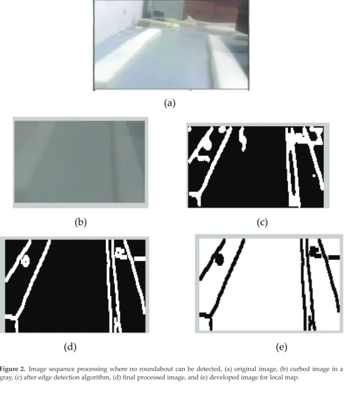
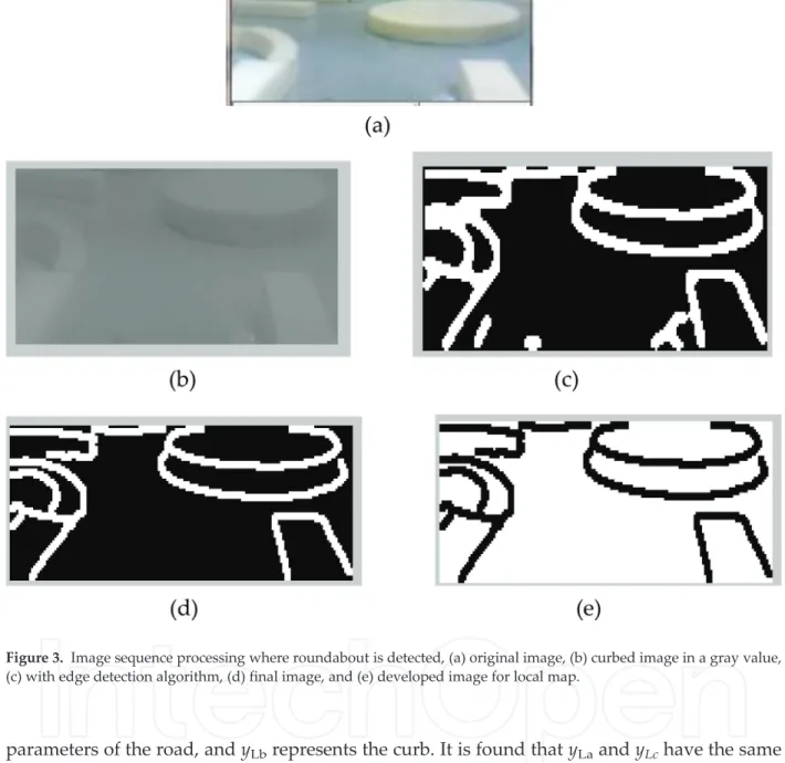
The developed image sequences after processing looked like the one shown inFigures 2
and 3, which are used later on for Laser Simulator-based roundabout detection. Also,
Figures 8–11 portrayed in Section 4 show the capability of the algorithm to develop the
local map in the indoor and outdoor road environments.
3.2. Laser range finder
LRF measurements are used to localize the robot in environments and for building 2D local map. As previously mentioned, this device can scan an area with 240 at 100 ms/scan. The
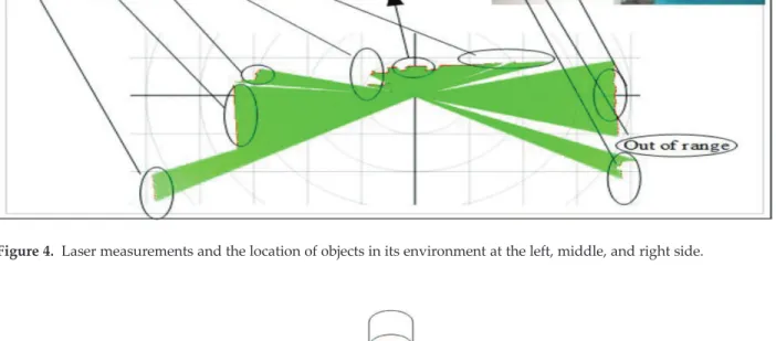
surrounding environments in the LRF measurements look like the one shown inFigure 4. Two coordinate systems are used to characterize the measurements of LRF as depicted in
Figure 5, which are: LRF measuring coordinate and LRF environment coordinate systems. Since the LRF measurements are scanned starting from the origin point, the calculation is done based on the right triangle as depicted inFigure 5.
If the laser measurement of components inyLdirection is compared at points a, b, and c, one
yLc ¼Lc, xLc ¼0
yLa¼Lasin β¼Lc, xLc ¼Lacos β yLb¼Lbsin β, xLb ¼Lbcos β
(3)
La,Lb, andLcare the length of laser measurements at point a, b, and c, respectively, as shown in Figure 5. βis the angle between the measurement point and the platform coordinate system which can be calculated from the scan area angle Lθ = (0
–240). yLa and yLc represent the
Figure 2. Image sequence processing where no roundabout can be detected, (a) original image, (b) curbed image in a gray, (c) after edge detection algorithm, (d) final processed image, and (e) developed image for local map.
parameters of the road, andyLbrepresents the curb. It is found thatyLaandyLchave the same
length inydirection; however, the length ofyLbis different and can be written as follows:
yLb ¼yLc ZRb
sinð Þr )yLc yLb ¼ ZRb
sinð Þr (4)
ZRb=hc,hcis idetified as the road curbed height which is known as a threshold in the program.
ris defined as the LRF rays and the floor. For obstacle detection, two successive scan measure-ments (iandii) have to be compared with each other inyLdirection in the location betweene anddas illustrated inFigure 5to find the obstacles ahead of the robot as shown in Eqs. (5)–(7): Figure 3. Image sequence processing where roundabout is detected, (a) original image, (b) curbed image in a gray value, (c) with edge detection algorithm, (d) final image, and (e) developed image for local map.
yc yd ¼ ZRd
sinð Þr and xd ¼-Ldcos β
(5)
yc ye¼ ZRe
sinð Þr and xe¼-Lecos β
, (6)
The width of the obstacle can be calculated as:
Wob¼xe xd (7)
Figure 4. Laser measurements and the location of objects in its environment at the left, middle, and right side.
From previous calculation, one can define the parameters that will be used later for road discovering by LRF as shown inFigure 5as:
• Road fluctuations (height of objects with reference to the laser device) as follows:
rfn ¼rncos β
(8) • Road width (side distance with reference to the laser device) as follows:
rwn ¼rnsin β (9)
rnis the dimension of LRF signals forn-th LRF measurements. • Curb threshold:rf0 inβ=0
is used as reference and the other fluctuation measurements (rfn) on the left and right side in the same scan are compared with this base line. If the deviation between the reference point and other measurement values exceeds the predefined thresholdth, this point will be considered as a road curb. Otherwise, it will be considered as a road. This operation is repeated with all measurements as follows:
rfn rf0≥ th (10)
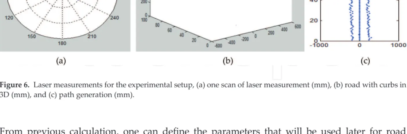
The LRF driver for reading the data from USB connection in real-time is developed in MATLAB. It includes some functions to identify, configure and get data from the sensors as further detailed out in Appendix B. The algorithm for detecting the curbs of road based on the previous mentioned Eqs. (3)–(10) is developed and implemented in the road environments as shown inFigure 6. The LRF is the main sensor for the calculation of the robot path within the environments, which produces the results through using the LRF to generate the equations for path planning as shown in Sections 4.1 and 4.2.
3.3. Odometry
Two rotary encoders (B106) were used to estimate the position of robot, which are connected through dual brush card pins (IFC-BH02) to the two differential wheels. The full rotation of Figure 6. Laser measurements for the experimental setup, (a) one scan of laser measurement (mm), (b) road with curbs in 3D (mm), and (c) path generation (mm).
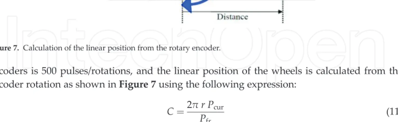
encoders is 500 pulses/rotations, and the linear position of the wheels is calculated from the encoder rotation as shown inFigure 7using the following expression:
C¼2
πr Pcur
Pfr (11)
Cis the accumulative path of robot,ris the radius of wheel,Pcuris the number of pulses in the current position, andPfris the number of pulses for one full rotation of the encoder.
Two encoders were used in the proposed system, and the accumulative path will be calculated as an average value of both encoders as follows:
Cav ¼
C1þC2
2 (12)
4. Navigation system results and discussion
The proposed WMR is able to navigate autonomously on the road following and negotiates effectively the curvature of a standard roundabout. The robot is able to find the path starting from the predefined start pose until it reaches the pregoal position using the LS approach for the local map that was identified by the robot sensors such as camera, the LRF, and odometry measurements. Normally, the start and goal positions are determined using the DGPS system, and the robot uses this information to detect the direction of the roundabout exit. Since the proposed robot is navigating in a relatively small area (about 10–30 m), it is not useful to use GPS. Instead one can simply inform the robot about the roundabout exit direction, goal position before it starts to move. The goal position can be determined as how much distance the robot should travel after passing through the roundabout, for example, the goal is located at eastern part of the exit of the roundabout (i.e., 270
) with a distance equals to 20 m. The path that the robot will follow in the environment can be adjusted in the program of the navigation system as in middle, left or right. It is desired that the robot should navigate in the middle of the road for all the experiments. The velocity of the robot during navigation is adjusted in the range of 7–10 cm/s.
During navigation on the road, our Laser Simulator approach is used to detect the roundabout when it is present in the local map identified by the camera [27–29]. The sensor fusion including LRF and encoders is used to estimate the position of robot within the environments. Figure 7. Calculation of the linear position from the rotary encoder.
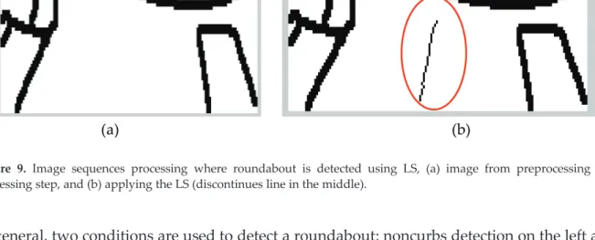
In general, two conditions are used to detect a roundabout; noncurbs detection on the left and right and discovering ellipse in the image as shown inFigures 8and9.
4.1. Road following
In the road following area, the camera, encoders, and laser are combined together to find the collision-free path. The camera is used for roundabout detection when it figures out using Laser Simulator. LRF is utilized for detecting the road curbs and localizing the robot in the environ-ment. The encoder’s measurements are used for estimating the current position of robot within environments. The generation of robot path is described in the following paragraphs.
4.2. Roundabout navigation results
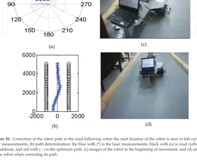
The results show the capability of the roundabout path planning algorithm to find the right trajectory with a small deviation in comparison to the optimum path as shown inFigure 10. Figure 8. Image sequences processing where no roundabout can be detected using LS, (a) image from preprocessing and processing step, and (b) applying the LS (continues line in the middle).
Figure 9. Image sequences processing where roundabout is detected using LS, (a) image from preprocessing and processing step, and (b) applying the LS (discontinues line in the middle).
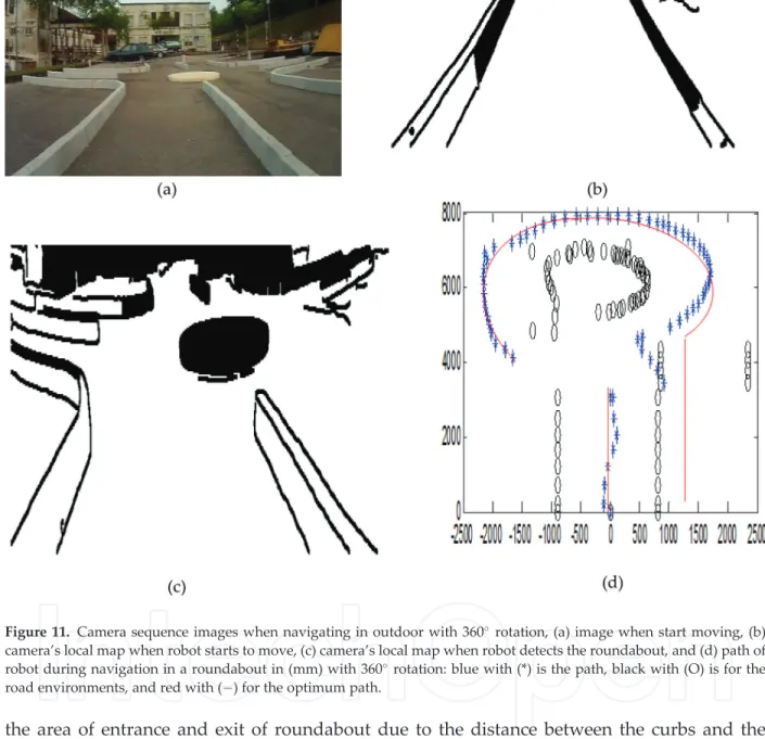
Figure 11shows how the camera, encoders, and laser range finder are used for path planning and execution from start to goal position. It also shows the local map built from camera sequence frames, where the developed view presents the curbs of the road environment of road in images. The camera’s local map is determined for each image in the sequences of video frames as shown in Figure 11(b) and (c), and the LS is applied to find the roundabout. Figure 11(c)shows the last image, where the roundabout is detected.
By applying the algorithm of cameras, laser range finder, and odometry described in Section 3, one can determine the path of robot as inFigure 11(d). It is noticed that the part of roundabout in the entrance and exit areas is not occurred in the roundabout environment, due to that the laser still does not reach that area, but it is calculated based on a mixed algorithm of camera and laser range finder. The road following curbs are shown inFigure 11(d), where the entrance to the roundabout is located on the left side, and the exit is located on the right. The path of the robot looked smooth especially with the indoor environments in comparison with the opti-mum path (continuous red line); however, there is a deviation in the outdoor measurements in Figure 10. Correction of the robot path in the road following when the start location of the robot is near to left curb, (a) laser measurements, (b) path determination: the blue with (*) is the laser measurements, black with (o) is road curbs and roundabout, and red with ( ) is the optimum path, (c) images of the robot in the beginning of movement, and (d) images of the robot when correcting its path.
the area of entrance and exit of roundabout due to the distance between the curbs and the roundabout center.
5. Conclusion
A practical implementation of the WMR online path navigation using laser simulator (LS) and sensor fusion in the road environments is presented in this thesis. The mobile robot is sup-posed to navigate on the roads in real time and reach the predetermined goal while Figure 11. Camera sequence images when navigating in outdoor with 360rotation, (a) image when start moving, (b)
camera’s local map when robot starts to move, (c) camera’s local map when robot detects the roundabout, and (d) path of robot during navigation in a roundabout in (mm) with 360rotation: blue with (*) is the path, black with (O) is for the
discovering and detecting the roundabout. A complete modeling and path determination of the roundabout intersection environments for autonomous mobile robot navigation is derived and presented in this chapter. The LS approach was used for road roundabout environment detection; whereas, the sensor fusion involves the laser range finder (LRF), and odometry was used to generate the path of the robot and localize it within its terrain. The local maps were built using both the camera and LRF to estimate the road border parameters such as road width, curbs, and roundabout in 2D. The algorithm of the path generation is fully derived within the local maps and subsequently implemented in two ways; first, considering the direct use of the sensor fusion data for path planning without applying localization and control algorithms and second, taking into account a complete model-based navigation including localization, path planning, and control schemes.
Author details
Mohammed A. H. Ali1* and Musa Mailah2
*Address all correspondence to: [email protected]
1 Faculty of Manufacturing Engineering, Universiti Malaysia Pahang, Pekan, Malaysia 2 Faculty of Mechanical Engineering, Universiti Teknologi Malaysia, Johor Bahru, Malaysia
References
[1] Ali MAH. Autonomous mobile robot navigation and control in the road following and roundabout environments incorporating laser range finder and vision system [PhD thesis]. UTM; 2014
[2] Ali MA, Mailah M, Yussof WA, Hamedon ZB, Yussof ZB, Majeed AP. Sensors fusion based online mapping and features extraction of mobile robot in the road following and round-about. IOP Conference Series: Materials Science and Engineering. 2016;114(2016):1-12 [3] Miguel A. VIRTUOUS: Vision-based road transport-system for unmanned operation on
urban-like scenarios. IEEE Transactions on Intelligent Transportation Systems. 2004;5(1): 69-83
[4] Matsushita Y, Miura J. On-line road boundary modeling with multiple sensory features, flexible road model and particle filter. Robotics and Autonomous Systems. 2011;59(1):274-284 [5] Seung H, Chi W, Sung C, Minyong P. Outdoor navigation of a mobile robot using differential GPS and curb detection. In: Proceedings of IEEE International Conference on Robotics and Automation; April 10–14. Roma, Italy: IEEE; 2007. pp. 3414-3419
[6] Kazunori O, Takashi T, Bunji S, Shoichi M, Shin Y. Outdoor navigation of a mobile robot between buildings based on DGPS and Odometry data fusion. In: Proceedings of IEEE
International Conference on Robotics and Automation; September 14–19. Taipei, Taiwan:
IEEE; 2003. pp. 1978-1984
[7] Jose G, Eduardo N, Stephan B. Autonomous navigation and map building using laser range sensors in outdoor applications. Journal of Robotic Systems. 2000;17(10):565-583 [8] Donghoon L, Sukyung S, Kwangwoong Y, Jonghwan P, Hogil L. Sensor fusion
localiza-tion system for outdoor mobile robot. In: ICROS-SICE Internalocaliza-tional Joint Conference; August 18–21, 2009. Fukuoka, Japan: SICE; 2009. pp. 1384-1387
[9] Cristina C, Dolores B, Luis M. Compact modeling technique for outdoor navigation. IEEE
Transactions on Systems, Man, and Cybernetics—Part A: Systems and Humans. 2008;
38(1):9-24
[10] Florian A, Franz A, Sven L, Lukas G, Joerg D. An unmanned helicopter for autonomous
flights in urban terrain. In: German Workshop on Robotics; June 9–10. Braunschweig,
Germany: Aerospace Center (DLR). pp. 1-11
[11] Panzieri S, Pascucci F, Ulivi G. An outdoor navigation system using GPS and inertial platform. In: Proceedings of IEEE/ASME International Conference on Advanced Intelli-gent Mechatronics: IEEE/ASME; 2001. pp. 1346-1351
[12] Thrapp R, Westbrook C, Subramanian D. Robust localization algorithms for an autono-mous campus tour guide. In: Proceedings of IEEE International Conference on Robotics and Automation. May 21–26, 2001. Seoul, Korea: IEEE; 2001. pp. 2065-2071
[13] Kazuyuki K, Cheok K, Kajiro W, Fumio M. Accurate differential global positioning system via fuzzy logic Kalman filter sensor fusion technique. IEEE Transactions on Industrial Electronics. 1998;45(3):510-528
[14] Cherif S, El-Najjar M, François C. Multi-sensor fusion method using dynamic Bayesian network for precise vehicle localization and road matching. In: Proceedings of 19th IEEE International Conference on Tools with Artificial Intelligence. October 29–31, 2007. Patras,
Greece: IEEE; 2007. pp. 146-151
[15] Chao G, Michael S, John R. Towards autonomous wheelchair systems in urban environ-ments. In: Howard A et al., editors. Field and Service Robotics. Vol. 7. Heidelberg-Berlin: Springer-Verlag; 2010. pp. 13-23
[16] Goldbeck J, Huertgen B, Ernsta S, Kelch L. Lane following combining vision and DGPS. Journal of Image and Vision Computing. 2000;18:425-433
[17] Nebot E, Sukkarieh S, Hugh D. Inertial navigation aided with GPS information. In: IEEE
Conference on Mechatronics and Machine Vision in Practice. September 23–25, 1997.
Toowoomba, Australia: IEEE; 1997. pp. 169-174
[18] Eric N, Jacques G, Tarbouchi M, Umar I, Aboelmagd, N. Enhanced mobile robot outdoor localization using INS/GPS integration. In: International Conference on Computer Engi-neering and Systems ICCES 2009. December 14–16, 2009. Cairo, Egypt: IEEE Xplore; 2009.
[19] Campbel N, Pout M, Priestly M, Dagless E, Thomas BT. Autonomous road vehicle navi-gation. Engineering Applications of Artificial Intelligence. 1994;7(2):177-190
[20] Jing-Chuan W, Shiyu H, Zhang X, Weidong C. Mobile robot localization in outdoor environments based on infrared vision. In: International Conference on Intelligent
Com-puting for Sustainable Energy and Environment LSMS/ ICSEE 2010. September 17–20,
2010. Wuxi, China: Springer-Verlag; 2010. pp. 33-41
[21] Locchi L, Kanolige K. Visually realistic mapping of a planar environment with stereo. In: Proceedings of Seventh International Symposium on Experimental Robotics (ISER). December 10–13, 2000. Honolulu, Hawaii: Springer; 2000. pp. 521-532
[22] Castellanos J, Martfinez M, Neira J, Tadus D. Simultaneous map building and localization for mobile robot: A multi-sensor fusion approach. In: Proceedings of IEEE International Conference on Robotics and Automation. May 16–20, 1998. Leuven, Belgium: IEEE; 1998. pp. 1244-1249
[23] Leonimer F, Jose F. Trajectory planning for non-holonomic mobile robot using extended Kalman filter. Mathematical Problems in Engineering. 2010;2010:979205, 22 pp
[24] Hong T, Christopher R, Tommy C, Michael S. Road detection and tracking for autono-mous mobile robots. In: Proceedings of the SPIE 16th Annual International Symposium on Aerospace/Defense, Sensing, Simulation and controls. April 1–5. Orlando, FL: SPIE; 2002. pp. 1-8
[25] Aneesh C, Yuta S. Road-crossing landmarks detection by outdoor mobile robots. Journal of Robotics and Mechatronics. 2010;22(6):708-717
[26] Labayrade R, Royere C, Gruyer D, Aubert D. Cooperative fusion for multi-obstacles detec-tion with use of stereovision and laser scanner. Autonomous Robots. 2005;19(2):117-140
[27] Ali M, Mailah M, Tang HH. A novel approach for visibility search graph based path planning. In: 13th Int. Conf. Robot., Control Manuf. Syst.; Kuala-Lumpur, Malaysia, April 2–4, 2013. pp. 44-49
[28] Ali M, Mailah M, Tang HH. Implementation of laser simulator search graph for detection and path planning in roundabout environments. WSEAS Transactions on Signal Processing. 2014;10(2014):118-126
[29] Ali MAH, Yusoff WABW, Hamedon ZB, Yusssof ZBM, Mailah M. Global mobile robot path planning using laser simulator. In: 2nd IEEE International on Robotics and Manufacturing Automation (ROMA); Ipoh: Malaysia; 2016