Available online throug
ISSN 2229 – 5046
MIXED CONVECTION FLOW IN A VERTICAL CHANNEL FILLED WITH POROUS
MEDIUM WITH BOUNDARY CONDITIONS OF THIRD KIND WITH HEAT
SOURCE/SINK-BRINKMAN MODEL
J. C. Umavathi* & Jaweriya Sultana
Professor in the Department of Mathematics, Gulbarga University, Gulbarga-585 106, Karnataka, India
(Received on: 03-12-12; Revised & Accepted on: 15-01-13)
ABSTRACT
T
he effect of mixed convection in a vertical channel with porous medium is analysed in the present study with heat source or sink using Brinkman model. The plate exchanges heat with external fluid. Both equal and of different reference temperature of the external fluid is considered. The governing equations are solved numerically by using Runge-Kutta fourth order shooting method and analytically by using pertubation method. The effect of various parameters involved in the problem are illustrated graphically. The analytical and numerical solutions agree very well for small values of pertubation parameter. In the absence of porous parameter and heat source or sink the result agree with that of Zanchini [1].Keywords: Mixed convection; porous medium; Runge-Kutta method; perturbation parameter; Heat source; Heat sink.
1. INTRODUCTION
Forced and mixed convection in porous channels have been the focus of a variety of numerical studies and modeling efforts. Free and mixed convection on vertical surfaces under various thermal boundary conditions and external flow conditions remain problems of focus both experimentally and analytically. The literature on heat and mass transfer in porous media continues to expand, and several studies of a very fundamental nature capture the breadth of recent activity are published recently e.g. Nield and Bejan [2], Vafai [3], Bejan et al. [4], and Pop and Ingham [5], is motivated by numerous applications of this class of phenomena in the modern technologies. The large number of applications, such as, oil extraction, fluid flow in geothermal reservoirs, solid matrix heat exchangers, iron blast furnaces, energy efficient drying processes, ground water hydrology, solidification of casting etc. Lauriat and Prasad [6] investigated the free convection in a vertical porous layer and in a vertical enclosure filled with a porous medium. Hadim and Chen [7] carried out a numerical study of buoyancy-aided mixed convection in an isothermally heated vertical channel filled with a fluid saturated porous medium.
Recently, Ali [8] analyzed the effect of lateral mass flux on the natural convection boundary layer induced by a heated vertical plate embedded in a saturated porous medium with an exponential decaying heat generation. Ishak et al. [9] presented the problem of mixed convection boundary layer flow over a vertical surface embedded in a thermally stratified porous medium assuming that the external velocity and surface temperature with an exponential decaying heat generation. The study of heat generation in moving fluids is important in view of several physical problems such as those concerned with dissociating fluids. Possible heat generation effects may alter the temperature distribution and, therefore, the particle deposition rate. This may occur in such applications related to electronic chips and semi conductor wafers, nuclear reactor cores, fire and combustion modeling. In fact, the literature is replete with examples dealing with the heat transfer in laminar flow of viscous fluids.
Effect of the heat generation or absorption and thermophoresis on a hydromagnetic flow with heat and mass transfer over a flat plate was investigated by Chamkha and Issa [10]. Also the effects of the conjugate conduction-natural convection heat transfer along a thin vertical plate with non-uniform heat generation have been studied by Mendez and Trevino [11]. Recently Molla et al. [12] have investigated the natural convection flow with heat generation/absorption along a uniform heated vertical wavy surface. The convection in enclosures has become increasingly important in engineering applications. In particular, as high power electronic packaging and component density continue to increase substantially with the fast growth of electronic technology, effective cooling of electronic equipment has become warranted.
Corresponding author: J. C. Umavathi*
© 2013, IJMA. All Rights Reserved 295 The application of natural convection cooling for electronic equipment ranges from individual transistors to mainframe computers and from energy supplies to telephone switch boards. Recent technological implications have given rise to increased interest in combined free and forced convection flow in vertical channels in which the objective is to secure a quantitative understanding of a configuration having current engineering applications (Al-Hadharami et al., [13]). Parang and Keyhani [14] studied the fully developed buoyancy-assisted mixed convection in a vertical annulus by using Brinkman-extended Darcy model. Their results indicated that the Brinkman term could be neglected for lower Darcy number. Muralidar [15] performed a numerical calculation for buoyancy-assisted mixed convection in a vertical annulus by using the Darcy model. The results show that the Nusselt number increases with the Rayleigh number and/or Peclet number. Umavathi et al. [16-19] studied mixed convection in a vertical and horizontal porous channel.
In the past, the laminar forced convection heat transfer in the thermal entrance region of a rectangular channel has been analyzed either for the temperature boundary condition of the first kind, characterized by prescribed wall temperature (Wibulswas [20], Lyczkowski et al., [21] and Javeri, [22]) or for the boundary condition of the second kind, expressed by the prescribed wall heat flux (Hicken, [23] and Sparrow and Siegel, [24]). A more realistic condition in many applications, however, will be temperature boundary condition of third kind: the local wall heat flux is a linear function of the local wall temperature. Heat transfer in laminar region of a flat channel for the temperature boundary condition of third kind was explored by Javeri [25]. Javeri [26] investigated the influence of the temperature boundary condition of the third kind on the laminar heat transfer in the thermal entrance region of a rectangular channel. Later Zanchini [1] analyzed the effect of viscous dissipation on mixed convection in a vertical channel with boundary conditions of third kind. Kumari and Nath [27] analyzed the effect of localized cooling/heating and injection/suction on mixed convection flow on a thin vertical cylinder. Mahanti and Gaur [28] investigated the effects of the viscosity and thermal conductivity on steady free-convection flow of a viscous incompressible fluid along an isothermal vertical plate in the presence of heat sink. Umavathi and Prathap [29] found the exact solutions for the mixed convection flow of micro-polar fluid in a vertical channel with symmetric and asymmetric conditions in the presence of source or sink. Prathap Kumar et al [30] studied mixed convection magneto hydrodynamic and viscous fluid in a vertical channel.
Accordingly, the aim of the present paper is to explore the velocity and temperature fields in a vertical channel embedded with porous medium using boundary conditions of the third kind. Both equal and different reference temperatures of the external fluid as well as both equal and unequal Biot numbers are considered. In the absence of porous medium and heat source/sink the solutions obtained in this paper coincide with those of the Zanchini [1].
2. PROBLEM FORMULATION
Consider the steady and laminar flow of a Newtonian fluid in the fully developed region of a parallel-plate vertical channel filled with a porous material. The porous medium is isotropic and homogeneous. The X-axis lies on the axial plane of the channel, and its direction is opposite to the gravitational field. The Y-axis is orthogonal to the walls. The channel occupies the region of space−L/ 2≤ ≤Y L/ 2. The thermal conductivity, the thermal diffusivity, the dynamic viscosity and the thermal expansion coefficient of the fluid are considered constant. As customary, the Boussineq approximation and the equation of state will be adopted.
0[1 t(T T0)]
ρ ρ= −β − (1)
Moreover, it will be assumed that the only nonzero component of the velocity field U is the X-component of theU .
Thus, since
∇
.
U
=0, one has so that U depends only on Y.0 U X
∂ =
∂ (2)
The momentum balance equation along X and Y yields (Vafai and Tien, [31]). 2
0 2
0 1
( ) 0
t
P d U U
g T T
X dY k
ν
β ν
ρ ∂
− − + − =
∂ (3)
0 P
Y
∂ =
∂ (4)
whereP= +p ρ0gX. Since, on account of equation (4) P depends only onX, and hence equation (3) can be rewritten as 2
0 2
0 1
t t t
dP d U U
T T
g dX g dY k g
ν ν
β ρ β β
From equation (5), one obtains 2 2 0 1 t
T d P
X β ρg dX
∂ =
∂ (6)
3
3
t t
T d U dU
Y g dY k g dY
ν ν
β β
∂ = − +
∂ (7)
2 4 2
2 4 2
t t
T d U d U
g k g
Y dY dY
ν ν
β β
∂
= − +
∂ (8)
Both the walls of the channel will be assumed to have a negligible thickness and to exchange heat by convection with an external fluid. In particular, at Y = −L/ 2 the external convection coefficient will be considered as uniform with the value
1
h and the fluid in the region Y < −L/ 2 will be assumed to have a uniform reference temperature T1. At Y =L/ 2 the external convection coefficient will be considered as uniform with the value h2 and the fluid in the region Y >L/ 2 will be supposed to have a uniform reference temperatureT2 ≥T1. Therefore, the boundary conditions on the temperature field can be expressed as
1 1 / 2
[ ( , / 2)]
Y L T
K h T T X L
Y =−
∂
− = − −
∂ (9)
2 2
/ 2
[ ( , / 2) ]
Y L T
K h T X L T
Y =
∂
− = −
∂ (10)
On account of equation (7), equations (9) and (10) can be rewritten as 3 1 1 3 / 2 1
[ ( , / 2)]
t
Y L
gh
d U dU
T T X L
k dY K
dY
β ν
=−
− = − − (11)
3 2 2 3 / 2 1
[ ( , / 2) ]
t
Y L
gh
d U dU
T X L T
k dY K
dY
β ν
=
− = − (12)
It is easily verified that equations (11) and (12) imply that ∂T/∂X is zero both at Y= −L/ 2 and atY =L/ 2. Since equation (6) ensures that∂T/∂X does not depend on ,Y one is led to the conclusion that ∂T/∂X is zero everywhere. Therefore, the temperature Tdepends only onY, i.e. T=T Y( ). Thus, on account of equation (6), there exists a constant
Asuch as dP
A
dX = (13)
For the problem under investigation, the energy balance equation in the presence of viscous dissipation and heat source/sink can be written as (Aziz and Na, [32])
2 2 2 2 2 2 0 1
p t t t p
Q
T dU dP d U
U U
C dY K g dX g k g K C
Y dY
ν ν ν ν
α β ρ β β α
∂ = − − + −
∂ (14)
Equations (8) and (14) yield a differential equation forU , namely 2
4 2 2
2
4 2 2
0
1 1
t t t
p t t t
g g Qg
d U d U d U d P d U
U U
C dY k kK K g dX g k g
dY dY dY
β β µ β ν ν
α ν ν β ρ β β
= + + ± − +
(15)
The boundary conditions onUare
( / 2) ( / 2) 0
© 2013, IJMA. All Rights Reserved 297 Together with equations (11) and (12), which on account of equation (5), can be rewritten as
3 2
1
1 1 1
0 1 3 2 / 2 1 ( ) t Y L gh
h h U Ah
d U dU d U
T T
k dY K Kk K K
dY dY
β µ ν
=−
− − − = − − − (17)
3 2
2
2 2 2
2 0 3 2 / 2 1 ( ) t Y L gh
h h U Ah
d U dU d U
T T
k dY K Kk K K
dY dY
β
µ ν
=
− + + = − − (18)
Equations (15)-(18) determine the velocity distribution. They can be written in a dimensionless form by means of the following dimensionless parameters:
0
U u
U
= , T T0
T
θ= − ∆ , Y y D = , 3 2 t g TD Gr β ν ∆
= ,Re U D0
ν = , 2 0 U Br K T µ =
∆ , Pr ν α
= , Re Gr
λ= ,RT T2 T1 T − = ∆ , 1 1 h D Bi K = , 2 2 h D Bi K
= , 1 2
1 2 2 1 2 2
Bi Bi S
Bi Bi Bi Bi
=
+ + ,
2 QD
K
φ= , D
k
σ = . (19)
In equation (19), D=2L is the hydraulic diameter, while the reference velocity U0and the reference temperatureT0are given by 2 0 48 AD U µ
= − ; 1 2
0 2 1
1 2
1 1
( )
2 T T
T S T T
Bi Bi
+
= + − −
(20)
The reference temperature ∆T is given either by
2 1
T T T
∆ = − if T1<T2 (21)
or by 2 2 p T C D ν
∆ = if T1 =T2 (22)
Therefore, as in Barletta [33], the value of the dimensionless parameter RTcan be either 0 or 1. More precisely, RTequals 1
for asymmetric fluid temperatures, T1<T2, and equals 0 for symmetric fluid temperatures, T1 =T2. The dimensionless mean velocity u and the dimensionless bulk temperature θb are given
1 / 4
1 / 4 2
u udy
−
=
∫
(23)1 / 4
1 / 4 2
b u dy
u θ θ − =
∫
(24)On account of equation (13), for upward flowA<0, so that U0, Reand λ are positive and for downward flowA>0, while U0,Reand λare negative. By employing the dimensionless quantities defined in equation (19), equations (15)-(18) can be rewritten as
(
)
(
)
2
4 2
2 2 2 2
4 2 48
d u d u d u
Br u u
dy
dy λ σ σ φ dy φ σ
= + + − (25)
( 1 / 4) (1 / 4) 0
u− =u = (26)
2 2 3
2
2 3 1 / 4
1 1 1
1 4 48 1 2 T y R S
d u du d u
u
Bi dy Bi Bi
dy dy λ σ σ =− + − + = − + +
2 2 3 2
2 3 1 / 4
2 2 2
1 4 48 1 2 T y R S
d u du d u
u
Bi dy Bi Bi
dy dy λ σ σ = − + − = − − +
(28)
Similarly, equations (14) and (19) yield 2
2 2
2 2 2
2 48 2
d du d u
Br u u
dy
dy dy
φ
θ σ σ
λ = − + + − (29)
while from equations (5) and (19) one obtains 2
2 2 1
48 d u u
dy
θ σ
λ
= − + −
(30)
where the plus sign relate to heat absorption and minus sign relates to heat generation.
A Nusselt number can be defined at each boundary, as follows:
1
/ 2 1
[ ( / 2) ( / 2)] (1 )
T T Y L
dT Nu
R T L T L R T dY =−
=
− − + − ∆
2
/ 2 1
[ ( / 2) ( / 2)] (1 )
T T Y L
dT Nu
R T L T L R T dY =
=
− − + − ∆ (31)
The Nusselt numbers Nu1andNu2 can be employed to evaluate the heat fluxes at the walls. In fact, the heat flux per unit
area is given by
1 ( / )Y L/ 2
q = −K dT dY =− at the left wall, and by 2
/ 2
( / )Y L
q = −K dT dY = at the right wall. Let us first assumeRT =1. Then, from equation (31) one obtains
1
1 [ ( / 2) ( / 2)]
KNu
q T L T L
D
= − − − ;q2 KNu2[ ( / 2)T L T( L/ 2)]
D
= − − − (32)
The heat flux densitiesq1 and q2can also be expressed as
1 1[ ( / 2) 1]
q = −h T −L −T ; q2 = −h T2[ 2 −T L( / 2)] (33)
Equations (32) and (33) yield
(
)
1 22 1
1 2
[ ( / 2)T L T( L/ 2)] T T 1 K Nu Nu
D h h
− − = − + +
(34)
Let us now assumeRT =0. Equations (31) yields
1 1
KNu
q T
D
= − ∆ and 2
2
KNu
q T
D
= − ∆ (35)
where ∆T is the reference temperature difference defined by equation (22). By employing equation (19), equation (31) can be written as
1
1 / 4 1
[ (1 / 4) ( 1 / 4) (1 )]
T T y
d Nu
R R dy
θ
θ θ =−
=
− − + − ; 2
1 / 4 1
[ (1 / 4) ( 1 / 4) (1 )]
T T y
d Nu
R R dy
θ
θ θ =
=
− − + − (36)
3. SOLUTIONS
i). Separated effects of buoyancy forces and viscous dissipation
© 2013, IJMA. All Rights Reserved 299 Equation (36). As a consequence; the dimensionless temperature field is independent of the dimensionless velocity fieldu. Moreover, equations (31)-(34) can be easily solved and yield
( )
( )
( )
( )
21 2 3 4 48
u=C Sinh σy +C Cosh σy +C Sinh φy +C Cosh φy + σ (37) for the case of heat absorption and
( )
( )
( )
( )
21 2 3 4 48
u=C Cosh σy +C Sinh σy +C Cos φy +C Sin φy + σ (38) for the case of heat generation respectively.
WithBi1 =Bi2 =Bi equations (37) and (38) can be rewritten as
u=C Sinh1
( )
σy +C Cosh2( )
σy +C Sinh3( )
φy +48σ2 (39) for the case of heat absorption andu=C Cosh1
( )
σy +C Sinh2( )
σy +C Sin4( )
φy +48σ2 (40) for the case of heat generation, respectively.In the limitBi→ +∞, one obtains the special case in which the boundaries of the channel are kept at the temperatures T1
andT2, respectively. In this limit, equation (19) yieldsS→1, so that equations (37) and (38) reduces to
( )
( )
( )
21 2 3 48
u=C Sinh σy +C Cosh σy +C Sinh φy + σ (41) for the case of heat absorption and
( )
( )
( )
21 2 4 48
u=C Cosh σy +C Sinh σy +C Sin φy + σ (42) for the case of heat generation, respectively.
By substituting equations (37) and (38) in equations (23) and (24), one obtains
(
)
(
)
(
)
(
)
(
)
(
)
(
2)
(
(
)
(
)
)
4
4 1 4 1 4 4 48 1 4 4
u= C φ Sinh φ − σ Cosh φ Tanh σ + σ − φ Tanh σ
{
}
2
1 2 3 4 5
6
2( )
b
b b b b b
b
φ σ θ
λ
− − + + + +
= (43)
for the case of heat absorption and
(
)
(
)
(
) (
)
(
)
(
2)
1 3
4 4 4 4 4 8
u = C σ Sinh σ + C φ Sin φ + σ
(
)
(
)
(
)
(
)
(
)
2 2
1 2 3 4
5
2( ) 1
b
b b b b
b
φ σ σ φ σ φ θ
λ
− + + + +
= (44)
for the case of heat generation, respectively.
Moreover, equations (30), (37) and (38) yield
(
2)
(
( )
( )
)
3 4
C Sinh y C Cosh y
φ σ
θ φ φ
λ
−
= − + (45)
for the case of heat absorption and
(
2)
(
( )
( )
)
3 4
C Cos y C Sin y
φ σ
θ φ φ
λ
+
= + (46)
In the absence of heat absorption/generation and porous parameter, equations (30), (36) and (37) reduces to
1 2
2SR yT ; Nu Nu 2RT
θ = = = (47)
which are the same solutions obtained by Zanchini [1].
Plots of uversus yevaluated through equation (37), are reported in figure 1 for λ=0,λ=1000, heat absorption co-efficientφ and Bi1 =Bi2 =10 for different values of porous parameter. Let us now consider the case of negligible
buoyancy forces with a relevant viscous dissipation, which corresponds toλ=Gr/ Re=0. Since a purely forced
convection occurs in this case, the solution for velocity becomes
( )
(
)
2 48 1 4 Cosh y u Cosh σ σ σ = − (48)
Indeed, both for symmetric and for asymmetric fluid temperatures, equation (48) is the solution of equations (25)-(30) whenλ =0. Equations (9), (10) and (19) yield the boundary conditions onθ, i.e,
1
1 1 / 4
4
1 ( 1 / 4)
2 T y SR d Bi dy Bi θ θ =− = + + − 2 2 1 / 4
4
1 (1 / 4)
2 T y SR d Bi dy Bi θ θ = = + −
(49)
On the account of equations (29), (48) and (49), the temperature can be expressed as
(
)
( )
5 ( ) 6 ( ) 1 2 2 3
C Sinh y C Cosh y f Cosh y f Cosh y f
θ= φ + φ + σ + σ + (50)
for the case of heat absorption and
(
)
( )
5 ( ) 6 ( ) 1 2 2 3
C Sin y C Cos y f Cosh y f Cosh y f
θ= φ + φ + σ + σ + (51)
for the case of heat generation, respectively.
Equations (31), (50) and (51) yield respectively as
(
)
(
)
(
)
(
)
(
)
(
)
5 6 1 2
1
5
4 4 2 2 4
2 4 1
T T
C Cosh C Sinh f Sinh f Sinh
Nu
R C Sinh R
φ φ φ φ σ σ σ σ
φ λ − − − = + −
(
)
(
)
(
)
(
)
(
)
(
)
5 6 1 2
2
5
4 4 2 2 4
2 4 1
T T
C Cosh C Sinh f Sinh f Sinh
Nu
R C Sinh R
φ φ φ φ σ σ σ σ
φ λ
+ + +
=
+ − (52)
for the case of heat absorption and
(
)
(
)
(
)
(
)
(
)
(
)
5 6 1 2
1
5
4 4 2 2 4
2 4 1
T T
C Cos C Sin f Sinh f Sinh
Nu
R C Sin R
φ φ φ φ σ σ σ σ
φ λ + − − = + −
(
)
(
)
(
)
(
)
(
)
(
)
5 6 1 2
2
5
4 4 2 2 4
2 4 1
T T
C Cos C Sin f Sinh f Sinh
Nu
R C Sin R
φ φ φ φ σ σ σ σ
φ λ
− + +
=
+ − (53)
for the case of heat generation, respectively.
© 2013, IJMA. All Rights Reserved 301
ii). Combined effects of buoyancy forces and viscous dissipation
In this section, both buoyancy forces and viscous dissipation are considered as non-negligible. First, equations (31)-(36) are solved by a perturbation series method. Then, the dimensionless temperature field is determined by means of equation (36). Let us consider the dimensionless parameter
Re Pr p gD Br C β
ε λ= = (54)
which is independent of the reference temperature difference∆T . The solutions of equation (31)-(36) can be expressed by the perturbation expansion
( )
20( ) 1( ) 2( ) . . .
u y =u y +εu y +ε u y + (55)
To obtain the solutions of equations (25)-(28) with the form (55), one first substitutes equation (55) in equations (25)-(28) and collects terms having like power ofε. Then, one equates the coefficient of
ε
to zero (Aziz and Na, [32]). Thus, one obtains a sequence of boundary value problems which can be solved in succession and can yield the unknown functionsun( )y .The boundary value problem for n=0 and n=1 are
(
)
(
)
4 2
2 2
0 0
0
4 2 48
d u d u
u
dy = σ φ dy φ −σ (56)
0( 1 / 4) 0(1 / 4) 0
u − =u = (57)
2 2 3
2
0 0 0
0
2 3
1 1 1 / 4 1
1 4
48 1
2 T
y
d u du d u R S
u
Bi dy Bi Bi
dy dy λ σ σ =− + − + = − + +
(58)
2 2 3
2
0 0 0
0
2 3
2 2 1 / 4 2
1 4
48 1
2 T
y
d u du d u R S
u
Bi dy Bi Bi
dy dy λ σ σ = − + − = − − +
(59)
(
)
2
4 2
2 2 2 2
0
1 1
0 1
4 2
du
d u d u
u u
dy
dy σ σ φ dy φσ
= + + ±
(60)
1( 1 / 4) 1(1 / 4) 0
u − =u = (61)
2 3 2
2
1 1 1
0
2 3
1 1 1 / 4
1
0 y
d u d u du
u
Bi Bi dy
dy dy
σ σ
=−
− + + = (62)
2 3 2
2
1 1 1
1
2 3
2 2 1 / 4
1
0 y
d u d u du
u
Bi Bi dy
dy dy
σ σ
=
+ − − = (63)
where plus sign relates to heat absorption and minus sign relates to heat generation.
The solutions of equations (56)-(63) are given by
( )
( )
( )
( )
20 1 2 3 4 48
u =C Sinh σy +C Cosh σy +C Sinh φy +C Cosh φy + σ (64)
( )
( )
( )
( )
(
)
(
)
(
)
(
)
(
(
)
)
(
(
)
)
(
(
)
)
(
(
)
)
( )
( )
( )
( )
1 5 6 7 8 5 6 7
8 9 10 11 12
13 14 15 16 17
2 2 2
2
u C Sinh y C Cosh y C Sinh y C Cosh y l Cosh y l Cosh y l Sinh y
l Sinh y l Cosh y l Cosh y l Sinh y l Sinh y
l yCosh y l ySinh y l yCosh y l ySinh y l
σ σ φ φ σ φ σ
φ σ φ σ φ σ φ σ φ
σ σ φ φ
= + + + + + + +
+ + + − + + + − +
+ + + +
for the case of heat absorption and
0 1 2 3 4 2
48
( ) ( ) ( ) ( )
u C Coshσy C Sinhσy C Cos φy C Sin φy
σ
= + + + + (66)
( )
( )
1 7 8
u =C Cosh
σ
y +C Sinhσ
y +C Cos9( )
φy +C Sin10( )
φy +l Cos1( )
φy +l Cos2(
2 φy)
+l Sinh3
(
2σy)
+l Sin4(
2 φy)
+l Cosh5( )
σy +l Sinh6 (σy Sin)( )
φy +l Cosh7( )
σy Sin( )
φy+l Sinh8 (σy Cos)
( )
φy +l ySinh9( )
σy +l yCosh10( )
σy +l ySin11 ( φy)+l yCos12( )
φy +l13 (67)for the case of heat generation, respectively.
The right-hand side of equations (64) and (66) coincides with that of equations (37) and (38) respectively and gives the dimensionless velocity for the case ofBr=0.
The dimensionless temperature θ can be written in the form
( )
( )
(
)
(
(
2)
)
2
27 26
3 7 4 8 2
( )
(C C Sinh) y (C C Cosh) y l σ l
φ σ
θ ε φ ε φ
λ λ φ σ
− −
= − + + + −
− (68)
for the case of heat absorption and
(
)
(
(
)
( )
(
)
( )
)
(
2)
3 9 4 10 14
1
C C Cos y C C Sin y l
θ φ σ ε φ ε φ
λ
= + + + + + (69)
for the case of heat generation, respectively.
Using the equations (68) and (69) yields the following expressions of Nu1andNu2 as
(
)
(
(
)
(
)
(
)
(
)
)
(
)
(
)
(
)
(
)
2
3 7 4 8 29
1
2
3 7 32 31
4 4
2 4 (1 )
T T
C C Cosh C C Sinh l
Nu
R C C Sinh l l R
φ σ φ ε φ ε φ φ φ ε
φ σ ε φ λ
− + − + + = − + + − + −
(
)
(
(
)
(
)
(
)
(
)
)
(
)
(
)
(
(
)
(
)
)
(
)
23 7 4 8 29
2
2 2
3 7 32 31
4 4
2 4 2 4 (1 )
T T
C C Cosh C C Sinh l
Nu
R C Sinh C Sinh l l R
φ σ φ ε φ ε φ φ φ ε
φ σ φ ε φ σ φ λ
− + + + +
=
− + − + − + −
(70)
for the case of heat absorption and
(
)
(
(
)
(
)
(
)
(
)
)
(
)
(
)
(
)
(
)
(
)
2
3 9 4 10
1
2
4 10
4 4 1
2 4 1 (1 )
T T
C C Sin C C Cos AN
Nu
R C C Sin AD R
φ σ φ ε φ ε φ ε
φ σ ε φ λ
− + + + + + = − + + + + −
(
)
(
(
)
(
)
(
)
(
)
)
(
)
(
)
(
)
(
)
(
)
23 9 4 10
2
2
4 10
4 4 1
2 4 1 (1 )
T T
C C Sin C C Cos AN
Nu
R C C Sin AD R
φ σ φ ε φ ε φ ε
φ σ ε φ λ
− + + − + +
=
− + + + + −
(71)
for the case of heat generation, respectively.
Equations (23), (55) and (64), (65), (68) yield the expression of the mean dimensionless velocity for the case of heat absorption as
(
)
(
(
)
)
(
)
(
)
(
)
(
(
)
(
)
)
4 6 8 4
2
4 ( 4) 4 ( 4) 4
48 1 4 4 1
u C C C Sinh C Cosh Tanh
Tanh ub
φ ε φ σ φ σ
σ σ σ ε
= + + −
© 2013, IJMA. All Rights Reserved 303 Similarly equations (23), (55) and (66), (67), (69) yield the expression of the mean dimensionless velocity for the case of heat generation as
(
)
2(
)
1 7 3 9
4( ) ( 4) (48 ) 4( ) ( 4) 1
u = C +εC σ Sinh σ + σ + C +εC φ Sin φ +εub (73)
4. NUMERICAL SOLUTION
The analytical solutions obtained in the preceding section include only two terms of the series, which is not applicable for large values of λi.e., for large values of buoyancy force. In many practical problems the values of λare usually large. Therefore a numerical scheme is used to solve non-linear boundary value problem using Runge-Kutta shooting method. The analytical solutions and numerical solutions are found and it is observed that this agreement is good enough to justify the validity of the numerical scheme for small values of the perturbation parameter.
5. RESULTS AND DISCUSSION
The problem of mixed convection flow and heat transfer in a vertical channel filled with porous medium with boundary conditions of third kind is investigated. The analytical solutions are found using regular perturbation method with product
of mixed convection parameterλ(Gr/ Re)and Brinkman number(Br)as the perturbation parameter. The analytical
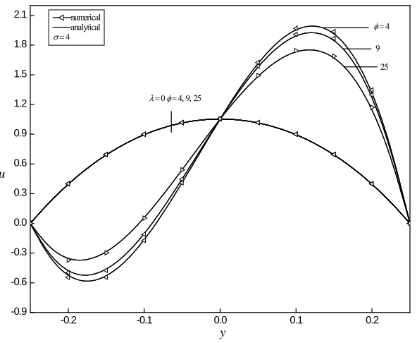
solutions are valid only for small values of the perturbation parameter. The restriction on the perturbation parameterεto be small is relaxed by finding the solutions of governing equations numerically using Runge-Kutta shooting method. The flow is also analyzed depending on the thermal characteristics of the parameters such as heat source/sink. Results are depicted graphically in figures 1-8 for heat sink and in figure 9 for heat source. In the absence of viscous dissipation, for equal Biot number there is a flow reversal near the cold wall for large values of mixed convection parameterλ (λ =1000)as seen in figure 1. In the absence of both viscous dissipation and mixed convection parameter, there is no effect of heat sink on the velocity (figure 1). As the heat sink parameter increases velocity decreases which is also observed from figure 1.
In the absence of mixed convection parameterλand viscous dissipation, the temperature field is linear indicating that the heat transfer is purely by conduction as can be seen in figure 2. The temperature field increases with an increase in
Brinkman number for all values of heat sink parameterφ. The temperature decreases substantially as heat sink
parameterφincreases in the presence of viscous dissipation as observed in figure 2 for equal Biot number. Similar results are also observed for unequal Biot number and hence not depicted graphically.
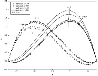
Figures 3a and 3b shows the variations of velocity and temperature fields for different values of perturbation parameterε for downward (ε <0) and upward (ε >0)flows. For upward flow velocity and temperature are increasing function ofε. The effect of εon velocity field is stronger while that on the temperature field is weaker. For downward flow velocity field is a decreasing function ofεwhere as the temperature field is an increasing function ofε. It is also seen from figure 3a that flow reversal occurs at both the left (ε>0) and (ε<0) right walls. This is because the perturbation parameterεimplies the enhancement of viscous dissipation which results in higher values of temperature which intern enhances the buoyancy force. Therefore increase in buoyancy force increases the fluid flow forλ >0and decreases the fluid flow forλ <0. Figures 1-3 also prove the good agreement between numerical and analytical solutions for small perturbation parameterεand the difference increases as εincreases.
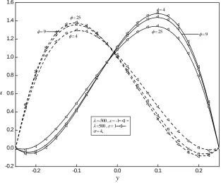
The effect of heat absorption coefficientφ is to decrease the velocity field near the hot wall for upward flow (λ >0) where as it increases the velocity field near the hot wall for downward flow (λ <0) as seen in figure 4a. Similar effect is there on the temperature field as seen in figure 4b.
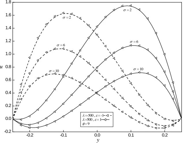
The effect of porous parameter on the flow is shown in figure 5. As the porous parameterσ increases the velocity decreases
for both upward and downward flow as seen in figure 5a. The effect of porous parameterσ is to reduce the temperature
field but the effect is almost invariant as seen in figure 5b.
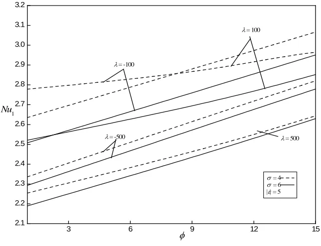
The Nusselt numberNu1is an increasing function of|ε|, while Nusselt numberNu2is an decreasing function of|ε|for fixed parameters φ and σ which are the similar results obtained by Zanchini [1] and hence not shown graphically. The
Nusselt number at the cold wall is an increasing function of heat absorption coefficientφfor upward and downward flow
at the hot wall as seen in figure 6b. However the magnitude of the Nusselt number at the hot wall is less for smaller values of mixed convection parameterλ.
The effect of mixed convection parameterλ for various values of |ε|is similar to the results obtained by Zanchini [1] and hence not presented. As the heat absorption coefficientφincreases, the average velocity decreases for upward flow where as increases for downward flow as seen in figure 7.
The effect of perturbation parameter εon the flow field for unequal Biot number for fixed values of heat absorption
coefficient φ and porous parameterσis again the similar results obtained by Zanchini [1]. That is as ε increases both velocity and temperature increases but the effect of εon temperature is more operative at the cold wall. For symmetric wall heating conditions, the heat absorption coefficient φ and porous parameterσ reduced the velocity and temperature fields for upward flow as seen in figures 8a and 8b respectively. Reversal effect is noticed on the flow field for downward flow (figures 8a and 8b) for equal Biot number. Similar results are obtained for the effects of φ, σ and ε for unequal Biot numbers.
The effect of heat generation coefficient φon the flow field is qualitatively same as that in case of heat absorption however we discuss the results where there are deviations from heat absorption. The effect of heat generation coefficient φis to
increase the velocity and temperature field asφ increases for upward flow at both the walls, where as velocity and
temperature decreases at both the walls for downward flow as seen in figures 9a and 9b respectively. The flow reversal is observed at the left wall and at the right wall for upward flow which is the similar result obtained for heat absorption coefficientφ.
6. CONCLUSIONS
The effect of mixed convection parameter, porous parameter and heat source/sink on fully developed mixed convection in a
vertical channel has been studied with boundary condition of third kind. Both the cases of asymmetric (RT =1) and
symmetric (RT =0) wall conditions with equal and different Biot number have been considered. The effect of heat sink is to reduce the flow field and heat source promotes the flow field. The effect of porous parameter reduces the flow field for both heat source and sink. The numerical and analytical solutions agree very well for small values of perturbation parameter. The results agree very well with that of Zanchini [1] in the absence of porous parameter and heat source/sink coefficient.
-0.2 -0.1 0.0 0.1 0.2
-0.9 -0.6 -0.3 0.0 0.3 0.6 0.9 1.2 1.5 1.8 2.1
y u
λ = 0φ = 4, 9, 25
9 25
φ = 4 numerical
analytical
σ = 4
© 2013, IJMA. All Rights Reserved 305
-0.2 -0.1 0.0 0.1 0.2
-0.6 -0.3 0.0 0.3 0.6 0.9 1.2 1.5
16 9
φ = 4
Br = 0, φ = 4,9,16
Br = 1
y
θ
numerical analytical
σ = 4
Fig. 2: Plots of θVs. yin the case RT =1, for some value of Br,λ=0andBi1 =Bi2 =10.
-0.2 -0.1 0.0 0.1 0.2
-0.3 0.0 0.3 0.6 0.9 1.2 1.5 1.8 2.1
numerical, λ =-500 numerical, λ =500 analytical, λ =-500 analytical, λ =500
φ = 9, σ =4
λ =-500
λ =500
ε = 6
0
-6
y u
-1
1
ε = 0
-0.2 -0.1 0.0 0.1 0.2 -0.4
-0.3 -0.2 -0.1 0.0 0.1 0.2 0.3 0.4
y
ε = 6
0 ε = -6
θ
ε = 1, -1, 0 numerical, λ =-500
numerical, λ =500 analytical, λ =-500 analytical, λ =500
φ = 9, σ =4
Fig. 3(b): Plots of θVs. yin the case RT =1, for some value ofλ ε =, 0andBi1 =Bi2 =10.
-0.2 -0.1 0.0 0.1 0.2
-0.2 0.0 0.2 0.4 0.6 0.8 1.0 1.2 1.4 1.6
φ = 9
λ =-500 , ε = -1 λ =500 , ε = 1 σ = 4,
φ = 4 φ = 25
φ = 25 φ = 9 φ = 4
y u
© 2013, IJMA. All Rights Reserved 307
-0.2 -0.1 0.0 0.1 0.2
-0.4 -0.2 0.0 0.2 0.4
φ = 9
λ =-500 , ε = -1
λ =500 , ε = 1
σ = 4
φ = 4
φ = 25
y
θ
Fig. 4(b): Plots of θVs. yin the case RT =1, for some value ofλ ε =, 0andBi1 =Bi2 =10.
-0.2 -0.1 0.0 0.1 0.2
-0.2 0.0 0.2 0.4 0.6 0.8 1.0 1.2 1.4 1.6 1.8
σ = 6
σ = 10
σ = 2
σ = 6
λ =-500 , ε = -1
λ =500 , ε = 1
φ = 9
σ = 2
σ = 10
y u
-0.2 -0.1 0.0 0.1 0.2 -0.4
-0.2 0.0 0.2 0.4
λ =-500 , ε = -1
λ =500 , ε = 1
φ = 9
σ = 2, 6, 10
y
θ
Fig. 5(b): Plots of θVs. yin the case RT =1, for some value of λ ε =, 0andBi1 =Bi2 =10.
3 6 9 12 15
2.1 2.2 2.3 2.4 2.5 2.6 2.7 2.8 2.9 3.0 3.1 3.2
Nu1
φ
λ = 500
λ = -100
λ = 100
λ = -500
σ = 4
σ = 6
|ε| = 5
© 2013, IJMA. All Rights Reserved 309
3 6 9 12 15
0.8 1.0 1.2 1.4 1.6 1.8 2.0 2.2 2.4 2.6
Nu2
φ
λ = 500
λ = -100
λ = 100
λ = -500
σ = 4
σ = 6
|ε | = 5
Fig. 6(b): Plots of Nu2Vs. φin the case RT =1, for some value of λandBi1 =Bi2 =10.
3 6 9 12 15
0.3 0.4 0.5 0.6 0.7 0.8 0.9 1.0 1.1
λ = 100
λ = 500
λ = -100
λ = -500
u
φ
λ = 500
λ = -100
λ = 100
λ = -500
σ = 4
σ = 6
|ε | = 5
-0.2 -0.1 0.0 0.1 0.2 0.0
0.1 0.2 0.3 0.4 0.5 0.6 0.7 0.8 0.9 1.0 1.1 1.2 1.3 1.4 1.5 1.6
u
y
ε = -4, σ = 6
ε = 4, σ = 2
φ = 9
φ = 25
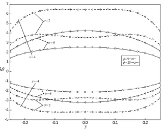
Fig. 8(a): Plots of u Vs. yin the case RT =0, for some value of λandBi1=Bi2 =10.
-0.2 -0.1 0.0 0.1 0.2
-5 -4 -3 -2 -1 0 1 2 3 4 5 6 7
σ = 6
σ = 6
σ = 2
σ = 2
λθ
y
ε = -4
ε = 4 φ
= 9
φ = 25
© 2013, IJMA. All Rights Reserved 311
-0.2 -0.1 0.0 0.1 0.2
-0.5 0.0 0.5 1.0 1.5 2.0 2.5
φ = 16
φ = 16
φ = 9
φ = 4
u
y
φ = 4
φ = 9
λ =-500 , ε = -1
λ =500 , ε = 1
σ = 4
Fig. 9(a): Plots of u vs.yin the case of ,for some values of λand Bi1=Bi1 =10.
-0.2 -0.1 0.0 0.1 0.2
-0.5 -0.4 -0.3 -0.2 -0.1 0.0 0.1 0.2 0.3 0.4 0.5
φ = 16
φ = 9
φ = 4 θ
y
λ =-500 , ε = -1
λ =500 , ε = 1
σ = 4
Table1 (a). Velocity for different values of ε and RT =1,Bi1=Bi2 =10,λ =| 500 |, M =4,φ=9
y ε = −7 ε =0 ε =7
Analytical Numerical Analytical Numerical Analytical Numerical
-0.25 0.000000 0.000000 0.000000 0.000000 0.000000 0.000000
-0.2 0.720528 0.750370 -0.049284 -0.049259 0.049315 0.122398
-0.15 1.058924 1.110638 0.109423 0.109456 0.292143 0.426375
-0.1 1.119512 1.185404 0.393593 0.393623 0.643000 0.824353
-0.05 0.987947 1.061000 0.731178 0.731199 1.026612 1.239359
0.0 0.737931 0.811743 1.055837 1.055845 1.373743 1.600883
0.05 0.435744 0.504411 1.302470 1.302464 1.616993 1.840432
0.1 0.144185 0.202267 1.402846 1.402828 1.686180 1.886589
0.15 -0.073297 -0.030681 1.281102 1.281079 1.503280 1.659753
0.2 -0.147882 -0.124898 0.848901 0.848882 0.977274 1.067185
0.25 0.000000 0.000001 0.000000 0.000000 0.000000 0.000000
Table1 (b). Temperature for different values of ε and RT =1,Bi1=Bi2 =10,λ =| 500 |, M =4,φ=9
y ε = −7 ε =0 ε =7
Anaytical Numerical Anaytical Numerical Anaytical Numerical
-0.25 -0.314290 -0.320101 -0.339598 -0.339597 -0.329839 -0.322000
-0.2 -0.230811 -0.238342 -0.262923 -0.262923 -0.248243 -0.236372
-0.15 -0.158931 -0.166802 -0.192175 -0.192175 -0.172401 -0.156851
-0.1 -0.092767 -0.100498 -0.125760 -0.125760 -0.101223 -0.082803
-0.05 -0.029885 -0.037335 -0.062179 -0.062179 -0.033838 -0.013409
0.0 0.030884 0.023806 0.000000 -0.000000 0.030884 0.052626
0.05 0.090520 0.083972 0.062179 0.062179 0.094474 0.117068
0.1 0.150297 0.144529 0.125760 0.125760 0.158753 0.181878
0.15 0.211950 0.207256 0.192175 0.192175 0.225419 0.248566
0.2 0.277603 0.274201 0.262923 0.262923 0.295036 0.316782
0.25 0.349356 0.347207 0.339598 0.339597 0.364905 0.381522
NOMENCLATURE
A constant
1
Bi Biot number,
(
h D1)
K2
Bi Biot number,
(
h D2)
KBr Brinkman number,
(
2)
(
)
0
U K T
µ ∆
P
C specific heat at constant pressure
D hydraulic diameter, 2L
g acceleration due to gravity
Gr Grashof number,
(
3)
2gβ∆TD ν
1
h , h2 external heat transfer coefficients
K thermal conductivity
k permeability of porous media
L channel width
1, 2
Nu Nu Nusselt numbers
p non-dimensional pressure gradient
P difference between the pressure and the
hydrostatic pressure,p+ρ0gX
Pr Prandtl number,
(
µCP)
KRe Reynolds number,
(
U D0)
νT
R temperature difference ratio
Q rate of internal heat
absorption/generation
T temperature
1, 2
T T reference temperatures of the external
fluid
0
T reference temperature
u dimensionless velocity in the X- direction
u mean value of u
0
U reference velocity
U velocity component in the X-direction
x dimensionless stream wise coordinate
X stream wise coordinate
y dimensionless transverse coordinate
Y transverse coordinate
GREEK SYMBOLS
© 2013, IJMA. All Rights Reserved 313
β thermal expansion coefficient
ε dimensionless parameter,λBr
φ dimensionless parameter of the heat
absorption/generation,
(
QD2)
KT
∆ reference temperature difference
θ dimensionless temperature,
(
T−T0)
∆Tb
θ dimensionless bulk temperature
µ viscosity
ν kinematics viscosity,
µ ρ
0λ dimensionless parameter, Gr Re
ρ mass density,
0
ρ value of the mass density whenT =T0
σ porous parameter D k
7. REFERENCES
[1] Zanchini, E., Effect of viscous dissipation on mixed convection in a vertical channel with boundary conditions of the third kind, Int. J.Heat and Mass Transfer, vol. 41, pp. 3949-3959, 1998.
[2] Nield, D.A., Bejan, A., Convection in porous media, Springer, (third ed), Berlin 2006.
[3] Vafai, K., Hand book of Porous Media. Taylor and Francis, (Second ed), New York 2005.
[4] Bejan, A., Dincer, I., Lorente, S., Miguel, A. F., A. J. I. Reis., Porous and Complex Flow, Structures in Modern
Technologies, Springer, Berlin 2004.
[5] Pop, I., Ingham, D.B., Convective Heat Transfer, A Mathematical and Computational Modeling of Viscous Fluids and
Porous Medi,. Pergamon, Oxford, 2001.
[6] Lauriat, G., Prasad, V., Non-Darcian effects on natural convection in a vertical porous enclosure, Int. J. Heat Mass Transfer, vol. 32, pp. 2135-2148, 1989.
[7] Hadim, H.A., Chen, G., Numerical study of non-Darcy mixed convection in a vertical porous channel. J Thermophys.
Vol. 8 pp. 371–373, 1993.
[8] Ali, M.E., The effect of lateral mass flux on the natural convection boundary layers induced by a heated vertical plate embedded in a saturated porous medium with internal heat generation. Int J Therm Sci vol. 46 pp. 157–163, 2007.
[9] Ishak, A., Nazar, I., Pop, R., Mixed convection boundary layer flow over a vertical surface embedded in a thermally
stratified porous medium. Phys Lett A vol. 372 pp.2355–2358, 2008.
[10]Chamkha, A. J., Camille Issa., Effects of heat generation/absorption and the thermophoresis on hydromagnetic flow with heat and mass transfer over a flat plate, Int. J. Numerical Methods for Heat and Fluid flow, vol. 10 (4), pp.432- 448, 2000.
[11]Mendez, F., Trevino, C., The conjugate conduction-natural convection heat transfer along a thin vertical plate with non-uniform internal heat generation, Int. J. Heat Mass Transfer, Vol. 43, pp. 2739-2748, 2000.
[12]Molla, M. M., Hossain, M. A., Yao, L. S., Natural convection flow along a vertical wavy surface with heat
generation/absorption, Int. J. Thermal Science, vol.43, pp. 57-163, 2004.
[13]Al-Hadhrami, A.K., Elliott, L., Ingham, D. B., Combined free and forced convection in vertical channels of porous
media, Transp. Porous Media, vol. 49, pp. 265-289, 2002 doi: 10.1023/A: 1016290505000.
[14]Prang, M., Keyhani, M., Boundary effects in laminar mixed convection flow through an annular porous medium,
ASME J. Heat Transfer, vol. 32, pp.1039-1041, 1987.
[15]Muralidhar, M., Mixed convection flow in a saturated porous annulus, Int. J. Heat Mass Transfer, vol. 32, pp. 881-888, 1989. doi: 10. 1016/0017-9310(89)90237-8.
[16]Umavathi, J. C., Malashetty, M.S., Oberbeck convection flow of couple stress fluid in a vertical porous stratum, Int. J. Nonlinear Mechanics, vol. 34, pp.1037-1045, 1999.
[17]Umavathi J. C., Palaniappan, D., Oscillatory flow of unsteady Oberberck convection in an infinite vertical porous
stratum, AMSE, vol. 69, No.2, 35-60, 2000.
[18]Umavathi, J. C., Mallikarjun B Patil., Pop, I., On laminar mixed convection flow in a vertical porous stratum with
symmetric wall heating conditions, IJTP vol. 8, pp.127-140, 2006.
[19]Umavathi, J.C., Liu, I-Chuang, Prathap Kumar, J., Shaik Meera, D., Unsteady flow and heat transfer of porous media
sandwiched between viscous fluids, Appl. Math. Mech, vol. 31, pp. 1497-1516, 2010.
[20]Wibulswas, P., Laminar flow heat transfer in non circular ducts, Ph.D. Thesis, London University, 1966. (As reported by Shah and London in 1971).
[21]Lyczkowski, R. W., Solbrig, C. W., Gidaspow, D., Forced convective heat transfer in rectangular ducts-general case of wall resistance and peripheral conduction, Institute of Gas Technology Tech. Info, Center File 3229, 3424S, State, Street, Chicago, I11.60616, 1969 (as reported by Shah and London in 1971).
[22]Javeri, V., Analysis of laminar thermal entrance region of elliptical and rectangular channels with Kantorowich
method. Warme-und Stoffuberragung, vol. 9, pp. 85-98 1976.
[23]Hicken, E., Das temperaturfeld in laminar durchstromten Kanalen mit echteckquerschnitt bei unterschiedlicher
Beheizung der Kanalwade, Warme-und Stoffubertragung, vol. 1, pp. 98-104, 1968.
[25]Javeri, V., Heat transfer in laminar entrance region of a flat channel for the temperature boundary condition of the third kind, Warme-und Stoffubertragung Thermo-and fluid dynamics vol. 10, pp.137-144, 1977.
[26]Javeri, V., Laminar heat transfer in a rectangular channel for the temperature boundary condition of the third kind, Int. J. Heat Mass Transfer, vol. 10, pp.1029-1034, 1978.
[27]Kumari, M., Nath, G., Mixed convection boundary layer flow over a thin vertical cylinder with localized
injection/suction and cooling/heating, Int. J. Heat and Mass Transfer, vol. 47, pp. 969-976, 2004.
[28]Mahanthi N.C., Gaur, P., Effect of varying and thermal conductivity on steady free convective flow and heat transfer along an isothermal vertical plate in the presence of heat sink, J. Applied Fluid Mechanics, vol. 2, No. 1, pp. 23-28, 2009.
[29]Umavathi, J.C., Prathap Kumar, J., Mixed convection flow of micropolar fluid in a vertical channel with symmetric
and asymmetric wall heating conditions, Int. J. Appl. Mech. Engg., vol. 16, pp. 141-159, 2011.
[30]Prathap Kumar, J., Umavathi, J.C., and Basavaraj, Biradar, M., Mixed convection of magentohydrodynamic and
viscous fluid in a vertical channel, International Journal of Non-Linear Mechanics, vol. 46, pp. 278-285, 2011.
[31]Vafai, K., Tien, C. L., Boundary and inertia effects on flow and heat transfer in porous media. Int. J. Heat mass Transf., vol. 24, 195-203, 1981.
[32]Aziz, A., Na, T.Y., Perturbation Methods in Heat Transfer., New York, Hemisphere, 1st ed., 1984.
[33]Barletta, A., Laminar mixed convection with viscous dissipation in a vertical channel, Int. J. Heat and Mass Transfer, vol. 41, pp. 3501-3513, 1998.


![Implementation of Efficient Neighbor Route Discovery Protocol [ENRDP] for Position Verification in MANET](data:image/gif;base64,R0lGODlhAQABAIAAAP///wAAACH5BAEAAAAALAAAAAABAAEAAAICRAEAOw==)