Design of Two-Channel Low-Delay FIR
Filter Banks Using Constrained
Optimization
Robert Bregovi´c and Tapio Saram¨aki
Signal Processing Laboratory, Tampere University of Technology, Tampere, Finland
This paper shows the efficiency of using constrained optimization for designing two-channel low-delay finite impulse response filter banks. The filter banks under consideration are quadrature mirror filter(QMF)banks
and perfect reconstruction(PR)biorthogonal filter banks.
The design problems for both types of banks are stated as constrained minimization problems in forms that enable us to minimize the maximum of the stopband energies of the analysis filter(s) subject to the given passband
and transition band constraints of the filter(s)as well as
subject to the given allowable reconstruction error for QMF banks or the PR property for biorthogonal filter banks. For solving the given optimization problems a modified Dutta-Vidyasagar optimization technique has been used. The efficiency of the proposed design methods is illustrated by means of some examples.
Keywords: FIR filter banks, low-delay, two-channel, optimization, QMF, biorthogonal
1. Introduction
During the last two decades, filter banks have found various applications in many different areas such as speech coding, scrambling, im-age compression, and transmission of signals through channels of different bandwidths 1]–
3]. The main idea of using filter banks is
the ability of the system to separate in the fre-quency domain the signal under consideration into two or more signals or to compose two or more different signals into a single signal. Due to the filtering operations that are performed on the signal passing through the filter bank, a delay between the output and the input sig-nals is introduced. In many applications, it is desirable to keep this delay as short as possi-ble. When using linear-phase finite impulse
re-sponse(FIR)filters in synthesizing filter banks,
good filter properties result in many cases in high filter orders and in an intolerably high de-lay. In these applications, low-delay FIR filter banks have to be used. These filter banks are characterized by the property that the orders of the nonlinear-phase building-block FIR filters can be increased to improve the filter properties without increasing the overall delay.
For constructing low-delay FIR filter banks, quadrature mirror filter(QMF)banks and
per-fect reconstruction(PR)filter banks have been
used. For the low-delay QMF banks 4]– 6], the
analysis filters are quadrature mirror filters and the PR property cannot be achieved, whereas for PR biorthogonal filter banks 6]– 9], these
filters are related through the PR property and have different characteristics.
For designing low-delay QMF banks two itera-tive approaches have been presented by Xu, Lu, and Antoniou in 4]and 5]. The main drawback
in these iterative algorithms is that the transition band ripple of the amplitude response is not au-tomatically controlled and it is not straightfor-ward to find proper values for the parameters used in the procedures to give a satisfactory filter performance in the transition band. The larger the difference between the filter order and the desired filter bank delay, the more difficult the problem is.
Low-delay PR biorthogonal filter banks have been first introduced by Nayebi, Smith, and Barnwell in 7]and 8]. The filter banks
342 Design of Two-Channel Low-Delay FIR Filter Banks Using Constrained Optimization
Fig. 1.Two-channel filter bank.
suboptimal, as has been shown in some later pa-pers. However, they have made several impor-tant observations concerning the properties of low-delay filter banks that apply to PR biorthog-onal filter banks as well as to QMF banks. First, it is not advisable to design filter banks with a very small delay compared to the filter orders, because after a certain filter order for the same overall delay, larger orders result only in a neg-ligible improvement in the performance of the filter bank. Second, additional constraints are usually necessary in the transition bands of the filters due to the possible artifacts occurring in these bands. Abdel-Rahem, El-Guibaly, and Antoniou presented in 9] two approaches for
designing low-delay biorthogonal filter banks based on the Lagrange-multiplier method. Fil-ter banks designed by their method have bet-ter properties than those designed by Nayebi, Smith, and Barnwell. The method has, like for QMF banks, again problems with the passband and transition band ripples.
This paper shows how the above-mentioned problems can be solved in designing two-channel low-delay FIR filter banks by using constrained optimization. For both QMF banks and PR biorthogonal filter banks, the overall synthesis problem is stated in the form to which the al-gorithm of Dutta and Vidyasagar 10] can be
applied. Several examples are included that il-lustrate the efficiency of the proposed synthe-sis scheme in improving the filter bank perfor-mance. More details on how to apply the Dutta-Vidyasagar algorithm to designing filter banks can be found in 11] and 12]. A
comprehen-sive review on two-channel FIR filter banks has been given in 6].
2. Two-channelfilter banks
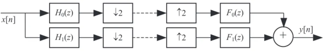
This section reviews some basic relations for two-channel filter banks. The block diagram for a two-channel filter bank is shown in Fig. 1 2].
It consists of an analysis filter bank followed by downsamplers, upsamplers, and a synthesis bank.
It is well known that the relation between the output and input of this system is expressible as
Y(z)=T(z)X(z)+A(z)X(;z) (1)
where the terms
T(z)=
1
2 H0(z)F0(z)+H1(z)F1(z)] (2a)
and
A(z)=
1
2 H0(;z)F0(z)+H1(;z)F1(z)](2b)
are the distortion transfer function and the alias-ing transfer function, respectively. The second term can be made zero by selecting the syn-thesis filters asF0(z) = 2H1(;z)andF1(z) =
;2H0(;z). In this case, the residual filter bank
distortion becomes
T(z)=H0(z)H1(;z);H1(z)H0(;z): (3)
To simplify the overall design problems to be described in the following sections, we use, in-stead ofH0(z)andH1(z), the following transfer
functions 6]:
G0(z)=
N0
X
n=0
g0 n]z ;n
H0(z)=
N0
X
n=0
h0 n]z ;n
(4a)
G1(z)=
N1
X
n=0
g1 n]z ;n
H1(;z)=
N1
X
n=0
(;1)
nh
1 n]z ;n
: (4b)
In the above, G0(z) and H0(z) are identical,
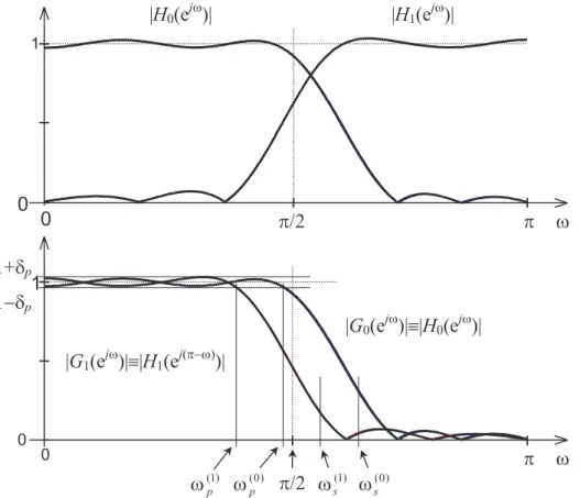
Fig. 2.Specifications forG0(z)andG1(z)as well as the relations betweenH0(z)andG0(z)andH1(z)andG1(z).
jG1(e
jω
)j=jH1(e
j(π;ω)
)so that the amplitude
response ofG1(z)is obtained from that ofH1(z)
by means of the substitutionπ ;ω ! ω and
vice versa. Fig. 2 exemplifies the above rela-tions in addition to showing the constraints for G0(z) andG1(z) that are used in the problems
to be stated in the following sections.
The main advantage of using the above trans-fer functionsG0(z)andG1(z), instead ofH0(z)
and H1(z), lies in the fact that they are both
lowpass filters. This makes their optimization more straightforward as they can be treated in the same way and the synthesis formulas can be expressed in a simplified manner.
3. Low-delay QMF banks
In this section, the definition of low-delay QMF banks is given, an appropriate design problem is stated, and an optimization procedure is sug-gested for solving this problem.
3.1. Definition of low-delay QMF banks
The low-delay QMF banks proposed by Xu, Lu, and Antoniou 4] are characterized by the
fol-lowing properties:
1. G1(z)=G0(z)= PN
0
n=0
g0 n]z ;n
, whereN0
is an odd integer.
2. jG0(e
jω
japproximates zero on ωs π](
stop-band)and unity on 0 ωp](passband).
3. T(z) = G0(z)]
2
+ G0(;z)]
2 approximates
the delayz;K withKis being an odd integer
satisfyingK <N0.
Because of Property 3, the impulse response of G0(z) cannot be symmetric so that all the
impulse-response values g0 n] for n = 0, 1,
:::,N0are unknowns. The reconstruction error
given by
jT(e
jω
);e ;jKω
j
=j G0(e
jω
)]
2
; G0(e
j(ω+π)
)]
2
;e ;jKω
344 Design of Two-Channel Low-Delay FIR Filter Banks Using Constrained Optimization
is desired to be made small in the overall base-band 0 π]. Due to the nonlinear-phase
charac-teristics, the performance ofG0(z)in the
pass-band and in the transition pass-band must also be controlled.
3.2. Design method for low-delay QMF banks
For given N0, ρs, ρp, δp, and δa as well as
K, the problem is to find the N0+1 unknown
impulse-response coefficientsg0 n]ofG0(z)= PN
0
n=0
g0 n]z ;n
to minimize
ε0 = Z π
ωs jG0(e
jω
)j
2dω
(6a)
subject to
max ω20ωp]
jjG0(e
jω
)j;1jδp
max ω2(ωpωs)
jG0(e
jω
)j;1δp
(6b)
and
max ω20π]
jT(e
jω
;e ;jKω
j= max ω20π]
jG0(e
jω
]
2
; G0(e
j(ω+π)
)]
2
;e ;jKω
jδa (6c)
where
ωp=(1;ρp)
π
2 and ωs =(1+ρs)
π 2:
Here the goal is to minimize the stopband en-ergy of the filter under consideration. The first condition of Eq.(6b)forces the maximum
pass-band deviation of the amplitude response from the unity to be less than or equal toδp, the
sec-ond csec-ondition of Eq.(6b)forces the transition
band maximum to be less than or equal to 1+δp,
and the third condition of Eq.(6c) guarantees
that the reconstruction error is smaller than or equal to δa. The above optimization problem
can be solved by properly applying the algo-rithm of Dutta and Vidyasagar 10](see, e. g.,
11]or 12]for details).
0 5 10 15 20
−0.5 0 0.5
Impulse response for E(z): K=7, N0+N1=22
0 5 10 15 20
−0.5 0
0.5 Impulse response for −E(−z)
0 5 10 15 20
0 0.5
1 Impulse response for T(z)=E(z)−E(−z)
n in samples
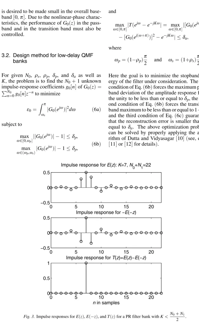
Fig. 3.Impulse responses forE(z),E(;z), andT(z)for a PR filter bank withK<
N0+N1
4. Low-delay PR biorthogonal filter banks
In this section, the definition of low-delay PR biorthogonal banks is given, an appropriate de-sign problem is stated, and an optimization pro-cedure is suggested for solving this problem.
4.1. Definition of low-delay PR biorthogo-nalfilter banks
For low-delay PR biorthogonal filter banksG0(z)
andG1(z), as given by Eqs.(4a)and(4b),
sat-isfy the following conditions:
1. The impulse responses of G0(z) and G1(z)
are not symmetric.
2. The impulse response ofE(z)=G0(z)G1(z)
= PN
0+N1
n=0
e n]z
;nsatisfies
e n]= (
1
2 for n=K
0 fornodd and n6=K (7)
whereKis an odd integer withK <
N0+N1
2 .
An example for an impulse response ofE(z)is
shown in Fig. 3. The second condition implies that the overall transfer function between the output and input isT(z)=E(z);E(;z)= z
;K
with K less than N0+N1
2 (compare Eqs. (3)
and (4) and see Fig. 3). The high number of
unknowns(altogetherN0+N1+2)and the PR
condition with the delay less than half the sum of the filter orders makes the synthesis of the overall system very nonlinear and complicated.
4.2. Design method for low-delay PR biorthogonalfilter bank
For given N0, N1, ρ(k)
p and ρ(k)
s for k = 0, 1,
andδpas well asK, the problem is to find the
adjustable coefficients of G0(z) and G1(z), as
given by Eqs.(4a)and(4b), to minimize
ε =max(ε0 ε1) (8a)
where
εk = Z π
ω(k) s
jGk(e
jω
)j
2dω for k
=0 1
(8b)
subject to max ω20ω
(k)
p ]
jjGk(e
jω
)j;1jδp fork =0 1
max ω2(ω
(k)
p ω
(k)
s )
jGk(e
jω
)j;1δpfork =0 1
(8c)
and
max ω20π]
jG0(e
jω
)G1(e
jω
)
;G0(e
j(ω+π)
)G1(e
j(ω+π)
)
;e ;jKω
j=0:
(8d)
Here, ω(k)
p =
(1;ρ (k)
p )π
2 and ω
(k)
s =
(1+ρ (k)
s )π
2 for k = 0, 1 are the passband and stopband
edges forG0(z)andG1(z)as shown in Fig. 2.
This problem is more complicated than the one stated in Section 3.2. Here the goal is to mini-mize the maximum of the stopband energies of the two filters under consideration. The condi-tion of Eq.(8d)guarantees that a PR filter bank
will be obtained. The above optimization prob-lem can also be solved by properly applying the algorithm of Dutta and Vidyasagar 10](see, e.
g., 11]or 12]for details).
5. Numerical examples
This section illustrates, by means of examples, some characteristics of two-channel low-delay QMF banks and low-delay PR biorthogonal fil-ter banks. In addition, the filfil-ter banks result-ing when applyresult-ing the proposed optimization scheme are compared to those obtained using other existing techniques.
Example 1. To show the flexibility of the pro-posed method, two low-delay QMF banks with N0 =31,K =15,ρp=ρs =0:19,δa =1:38
10;4, and different passband ripplesδ
p=0:087
and δp = 10
;4 have been designed. Fig. 4
shows the amplitude characteristics of the anal-ysis filters as well as the reconstruction errors for both filter banks. As expected, a smaller passband ripple results in a lower stopband at-tenuation. In both cases, the achieved passband ripple is very small. Only in the transition band, the amplitude characteristic exhibits the value of 1+δp. Moreover, the first filter bank has a
346 Design of Two-Channel Low-Delay FIR Filter Banks Using Constrained Optimization
0 0.1 0.2 0.3 0.4 0.5
−80
−60
−40
−20 0
Normalized frequency (ω/(2π))
Amplitude in dB
0 0.1 0.2 0.3 0.4 0.5
−2 0 2x 10
−4
Reconstruction
error
Fig. 4.Low-delay QMF banks withN0 =31 andK=15. The solid and dot-dashed lines show the amplitude
responses of analysis filters forδp=0:087 andδp=10
;4, respectively.
Example 2. It is desired to design a QMF
bank with K = 31, ρp = ρs = 0:172 (ωs =
0:586π),δa =3:2310
;3, andδ
p=1:610
;3.
Fig. 5 shows the amplitude characteristics of the analysis filters as well as the reconstruction er-rors for a low-delay QMF bank of orderN0 =63
designed using the proposed method and for a linear-phase QMF bank of orderN0 =31(
Ex-ample 1 in 6]). The low-delay filter bank
pro-vides significantly better stopband attenuations.
Example 3. A low-delay PR biorthogonal
fil-ter bank with N0 = N1 = 31, K = 15, δp =
3:810
;3, andρ (k)
p =ρ
(k)
s =0:2 fork=0 1 has
been designed. The requirements are the same as for the filter bank CLS32-15a in 9]. Fig. 6
shows the amplitude characteristics of the anal-ysis filters for both filter banks. Using the pro-posed method, filters with considerably better attenuations are obtained.
0 0.1 0.2 0.3 0.4 0.5
−80
−60
−40
−20 0
Normalized frequency (ω/(2π))
Amplitude in dB
0 0.1 0.2 0.3 0.4 0.5
−5 0 5x 10
−3
Reconstruction
error
Fig. 5. QMF banks forK=31. The solid and dot-dashed lines show the amplitude respones of analysis filters for the
0 0.1 0.2 0.3 0.4 0.5
−60
−40
−20 0
Normalized frequency (ω/(2π))
Amplitude in dB
Fig. 6.Low-delay PR biorthogonal filter bank withN0 =N1 =31 andK=15. The solid and dot-dashed lines show
the amplitude responses of analysis filters for the bank designed by the proposed method and the bank CLS32-15a
9], respectively.
0 0.1 0.2 0.3 0.4 0.5
−80
−60
−40
−20 0
Amplitude in dB
a)
0 0.1 0.2 0.3 0.4 0.5
−80
−60
−40
−20 0
Amplitude in dB
b)
0 0.1 0.2 0.3 0.4 0.5
−80
−60
−40
−20 0
Normalized frequency (ω/(2π))
Amplitude in dB
c)
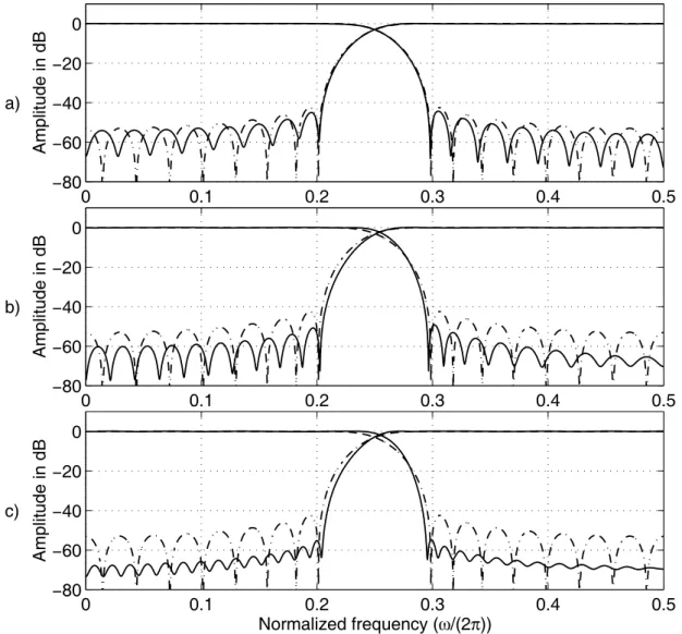
Fig. 7.Comparison forK=31 between low-delay PR biorthogonal filter banks with(a)N1=N0=33,(b) N1=N0=45,(c)N1=N0=63 and the linear-phase biorthogonal PR filter bank withN1=N0=31. The solid
348 Design of Two-Channel Low-Delay FIR Filter Banks Using Constrained Optimization
Example 4. It is desired to design low-delay PR biorthogonal filter banks forK = 31,δp=
0:01, andρ (k)
p =ρ
(k)
s =0:172 fork =0, 1. The
passband and stopband edges for both G0(z)
and G1(z) are thus located at ωp = 0:414π
and ωs = 0:586π respectively. Fig. 7
com-pares the optimized low-delay PR filter banks of orders N1 = N0 = 33, N1 = N0 = 45,
and N1 = N0 = 63, with a biorthogonal
fil-ter bank with linear-phase subfilfil-ters of orders N1 = N0 = 31. As can be expected, the
stop-band attenuations of the analysis filters in the low-delay filter banks increase as the filter or-ders are made higher.
References
1] H. S. MALVAR, Signal Processing with Lapped Transforms.Norwood: Artec House, 1992.
2] P. P. VAIDYANATHAN,Multirate Systems and Filter Banks. Englewood Cliffs, N. J.: Prentice Hall, 1993.
3] N. J. FLIEGE, Multirate Digital Signal Processing Period, Chicester: John Wiley and Sons, 1994.
4] H. XU, W.-S. LU ANDA. ANTONIOU, “An improved
method for the design of FIR quadrature mirror-image filter banks,”IEEE Trans. Signal Processing, vol. 46, pp. 1275–1281, May 1998.
5] W.-S. LU, H. XU ANDA. ANTONIOU, “A new method
for the design of FIR quadrature mirror-image Filter Banks,”IEEE Trans. Circuits Syst. II, vol. 45, pp. 922–926, July 1998.
6] R. BREGOVIC AND´ T. SARAMAKI¨ , “Two-channel FIR
filter banks — A tutorial review and new results,” inProc. Second Int. Workshop on Transforms and Filter Banks, Brandenburg, Germany, March 1999, TICSP #4, pp. 507–558.
7] K. NAYEBI, T. P. BARNWELLIIIANDM. J. T. SMITH,
“Time-domain filter bank analysis: A new design theory,”IEEE Trans. Signal Processing, vol. 40, pp. 1412–1429, June 1992.
8] K. NAYEBI, T. P. BARNWELLIIIANDM. J. T. SMITH,
“Low delay FIR filter banks: Design and evalua-tion,”IEEE Trans. Signal Processing, vol. 42, pp. 24–31, Jan. 1994.
9] E. ABDEL-RAHEEM, F. EL-GUIBALY ANDA. ANTO
-NIOU, “Design of low-delay two-channel FIR filter
banks using constrained optimization,”Signal Proc-sssing, vol. 48, pp. 183–192, Feb. 1996.
10] S. R. K. DUTTA AND M. VIDYASAGAR, “New
al-gorithms for constrained minimax optimization,”
Mathematical programming, vol. 13, pp. 140–155, 1977.
11] R. BREGOVIC AND´ T. SARAMAKI¨ , “A
general-purpose optimization technique for designing two-channel FIR filter banks,” inProc. European Signal Processing Conference, EUSIPCO-2000, Tampere, Finland, Sept. 2000, vol. I, pp. 369–372.
12] T. SARAMAKI¨ , “A generalized class of
cosine-modulated filter banks,” inProc. First Int. Workshop on Transforms and Filter Banks, Tampere, Finland, Feb. 1998, pp. 336–365.
Received:October, 2000 Accepted:November, 2000
Contact address: Robert Bregovi´c and Tapio Saram¨aki Signal Processing Laboratory Tampere University of Technology P. O. Box 553, FIN-33101 Tampere, Finland e-mail:[email protected]
ROBERTBREGOVIC´ was born in Varaˇzdin, Croatia, in 1970. He has received the degrees of Diploma Engineer and Master of Science in electrical engineering from Faculty of Electrical Engineering and Com-puting, University of Zagreb, Croatia, in 1994 and 1998, respectively. From 1994 to 1998 he worked as an assistant in the Department of Electronic Systems and Information Processing of the same Faculty. In 1999 he was a visiting researcher at the Tampere International Center for Signal Procesing. Since January 2000 he has been a researcher at the Signal Processing Laboratory of Tampere University of Technology working towards his doctoral degree.
His research interests include multirate signal processing, digital filter banks, optimization procedures for digital filter design and implemen-tation of algorithms on digital signal processors. Robert Bregovi´c is a member of IEEE Signal Processing Society and Croatian Society KoREMA.
TAPIOSARAMAKI¨ was born in Orivesi, Finland, on June 12, 1953. He has received the degrees of Diploma Engineer(with honors)and Doctor
of Technology(with honors)in electrical engineering from the
Tam-pere University of Technology, TamTam-pere, Finland, in 1978 and 1981, respectively.
Since 1977, he has held various research and teaching positions at Tam-pere University of Technology, where he is currently a Professor of Signal Processing and a Docent of Telecommunications. He is also a co-founder and a system-level designer of VLSI Solution Oy, Tampere, Finland, specializing in VLSI implementations of sigma-delta modu-lators and signal signal processing algorithms for various applications. Currently, Dr. Saram¨aki is an Associate Editor for IEEE Transactions on Circuits and Systems — II: Analog and Digital Signal Processing. In 1982, 1985, 1986, 1990, and 1998 he was a Visiting Research Fellow at the University of California at Santa Barbara.