DEVELOPMENT OF NOVEL POLYESTERS AS UNIQUE BIOMATERIALS
Sarah Mae Brosnan
A dissertation submitted to the faculty of the University of North Carolina at Chapel Hill in partial fulfillment of the requirements for the degree of Doctor of Philosophy in the
Department of Chemistry
Chapel Hill 2012
Approved by: Valerie S. Ashby Joseph M. DeSimone Sergei Sheiko
iii ABSTRACT
SARAH MAE BROSNAN: Development of Novel Polyesters as Unique Biomaterials (Under the direction of Valerie S. Ashby)
This thesis describes the development of unique biomaterials, particularly radiopaque and shape memory polyester materials. Specifically, the first developed examples of a functionalizable shape memory polymer, monodisperse shape memory polymer particles, and highly iodinated processable iodinated materials are discussed herein.
Materials with dynamically controllable surface chemistry and topography are highly desirable. Here, a functionalizable shape memory system has been designed that has uniquely remote-controllable functionality and geometry. This was accomplished by incorporating controlled amounts of an azide-containing monomer into a shape memory polymeric material. These materials are capable of physically changing their surface geometry over a range of length scales. Using copper assisted click chemistry, different surfaces are made. Materials with these combined features can change their presented geometry and functionality at tunable transition temperatures.
iv
v
vi
Acknowledgements
There are many people who were of great help to me over the course of my graduate career, and who certainly deserved to be acknowledged. First, I want to thank my advisor, Prof. Valerie S. Ashby, for allowing me to work in her group and for all her advice and support through the years (even through the dendrimer project!). I also very much need to thank all former and current members of the Ashby group, Jason Rochette, Duy Le, Hayden Black, Annie Jackson, and Sara Turner for their support and willingness for me to borrow their brains and glassware. I owe great thanks to Prof. Joe DeSimone and the members of his group (especially Chris Luft, Tim Merkle, Yapei Wang, and Mary Napier) for their time and knowledge. Also, a special thanks to Prof. Sergei Sheiko and Dr. Natalia Lebedeva for extremely valuable conversations for all my shape memory projects. I would like to thank Dr. Andrew Wang for introducing the need for new contrast agents to us—as the iodinated polyester project has been extremely exciting and fun to work on. I would like to thank Dr. Kyle Brennaman for help with the confocal Raman data. Additionally, I would like to thank Dr. Carrie Donley, of CHANL, for all her help with numerous projects and a lot her time working through problems related to said projects.
vii Table of Contents
List of Tables………..xi
List of Figures………xii
List of Abbreviations……….xvi
List of Symbols……….xviii
I. Introduction to Smart and Unique Biomaterials………...…....1
1.1 Shape Memory Materials……….….…..1
1.1.1 Shape Memory Materials for Biomedical Applications………....3
1.1.2 Shape Memory Biomaterials on the Micro- and Nanoscales………...4
1.1.3 Chemical Versatility with Shape Memory Materials………....…6
1.2 Review of Shape Shifting and Shape Memory Particles………...…7
1.2.1 Techniques to Make Polymeric Particles……….….7
1.2.2 Importance of Particle Size and Shape ………...9
1.2.3 Shape Shifting Particles……….….10
1.2.4 Shape Shifting Particles with Shape Memory Transitions………….…11
1.3 Review of CT Contrast Materials………...13
1.3.1 Small Molecule Contrast Agents………...13
1.3.2 Nanocarriers of Small Molecule Contrast Agents and Iodinated Nanoparticles ………..…..14
1.3.3. Metal-based Nanoparticle Contrast Agents………...17
1.4 References………..…...19
II Chemically and Physically Dynamic Surfaces………..…….…..24
2.1 Introduction………..….…24
2.2 Experimental Methods………...…..25
viii
2.2.2 Monomer and Polymer Characterization……….…….25
2.2.3. Film Characterization………...26
2.2.4 Monomer and Polymer Synthesis………...….….27
2.2.5 Functional Shape Memory Material Development………..28
2.2.6 Cytotoxicity………..….30
2.2.7 Degradation………..…...……30
2.3 Results and Discussion………..……31
2.3.1 Pre-Polymer Synthesis and Characterization………...31
2.3.2 Shape Memory Material Development and Characterization……...…33
2.3.3 Temperature Dependent Curing………...33
2.3.4 Macroscopic Shape Memory………...……..34
2.3.5 Micro- and Nanoscopic Shape Memory………..……35
2.3.6 Surface Functionalization and Analysis………...36
2.3.7 Static and Dynamic Contact Angle………...39
2.3.8 Dynamic Surface—Shape Memory after Primary Shape Functionalization………..41
2.3.9 Dynamic Surface—Shape Memory after Secondary Shape Functionalization………...…..43
2.3.10 Functionalization vs. Time vs. Shape………..……..44
2.3.10.1 Thick Films………...……..44
2.3.10.2 Thin Films………...……48
2.3.10.3 Confocal Raman………...…….51
2.3.11 Cytotoxicity………..…...54
2.3.12 Degradation………...….54
2.3.13 Microscopic Shape Memory Cycling………..55
ix
2.5 References………..….60
III Monodisperse Shape-Specific Shape Memory Polymeric Particles………...…..63
3.1 Introduction………..….63
3.2 Experimental………...…..64
3.2.1 Materials and Characterization………..…...64
3.2.2 Monomer and Polymer Characterization………...64
3.2.3. Film Characterization………...…..64
3.2.4 Cytotoxicity………..…….67
3.3 Results and Discussion………..……68
3.3.1 Thiol-ene Crosslinking………..…..68
3.3.2 Cytotoxicity………..…….70
3.3.3 Shape Memory Particle Synthesis………...….71
3.3.4 Various Shape Memory Particles………...73
3.3.5 Functionalization of Shape Memory Particles………..…..74
3.3.6 Porous Particles………...……77
3.4 Conclusion………...……...78
3.5 References………....80
IV Curable Iodinated Polyesters as Radiopaque Biomaterials………82
4.1 Introduction………....…..…….82
4.2 Experimental………...…..83
4.3 Results and Discussion………...……86
4.3.1 Monomer and Polymer Synthesis………...…..86
4.3.2 Cytotoxicity and Preliminary In Vivo Toxicity………...……90
4.3.3 Radiopacity………...……91
4.3.4 Degradation………...…92
x
4.3.6 Particle Synthesis………...….94
4.3.6.1 Scaling Up the Particle Synthesis………...……..97
4.3.6.2 Initial Purification Attempts………...…….99
4.4 Conclusion………....100
4.5 References………...102
V Conclusions and Future Work……….103
5.1 General Conclusions………..103
5.2 Future Work and Directions………..104
5.2.1 Shape Memory Surfaces……….104
5.2.2 Shape Memory Particles……….107
5.2.3 Radiopaque Polyester Materials………109
5.3 Reference………215
Appendix A: SUPPLEMENTAL MATERIALS FOR CHAPTER 2………112
Appendix B: SUPPLEMENTAL MATERIALS FOR CHAPTER 3………174
Appendix C: SUPPLEMENTAL MATERIALS FOR CHAPTER 4………..179
xi
Table 2.1: Properties of azide containing shape memory polymers………...…..33
Table 2.2: Properties of the azide containing SMP thermosets………...……34
Table 2.3: Temperature Dependant Curing ……….…...….35
Table 2.4: Functionalization vs. Time vs. Shape of Thick Films……….….…..…48
Table 3.1: Effect of Thiol-Ene Crosslinking………...…...69
Table 4.1: Properties of 2,2-bis(iodomethyl)-1,3-propanediol………...…….…….…87
Table 4.2: Iodinated Polymer Properties……….…...88
Table 4.3: Properties of the crosslinked polyesters ………..…...……..….89
xii
Figure 1.1: A cartoon demonstrating a shape memory cycle……….………3
Figure 1.2: Applications of SMP materials………...…….5
Figure 1.3: Shape memory on the micro- and nanoscales……….……6
Figure 1.4: Shape memory polymer system that contains a reactive functionality…….….7
Figure 1.5: The PRINTTM process and the various particle shape and sizes this process can yield………...9
Figure 1.6: Available shapes from Mitragotri's stretching method……….…...10
Figure 1.7: The effect of size and shape on particle uptake……….….11
Figure 1.8: Shape shifting PLGA particles………12
Figure 1.9: Shape shifting liquid crystalline particles...14
Figure 1.10: Structures of common contrast agents………...15
Figure 1.11: Micrographs of the resulting liposomes for use as both CT and MRI contrast agents………16
Figure 1.12: Structure of 2-methacryloyloxyethyl(2,3,5-triiodobenzoate), micrograph, and CT scan of particles………...17
Figure 1.13: Synthesis of the TaOx particles………19
Scheme 2.1: Synthesis of azide containing polyester……….32
Scheme 2.2: Endcapping of azide containing polyesters………...33
Scheme 2.3: Curing of azide containing polyester materials……….34
Figure 2.1: The macroscopic transition is a curly film………..……..36
Graph 2.1: A 3D SMP cycle performed using DMA………..…..36
Figure 2.2: Micro- and nanoscopic shape memory transitions………...37
Scheme 2.4: Surface modification of the azide containing shape memory crosslinked films………..…..38
Graph 2.2: XPS results for the blank, physisorbed, and clicked samples……….…...38
Graph 2.3: ATR-FTIR spectra of the flat blank and functionalized films……….…...39
xiii
with and without chemical functionality………..…....41
Graph 2.6: Dynamic contact angle data for the blank and functionalized films………41
Figure 2.3: Functionalized films through shape memory cycles……….…….42
Graph 2.7: Static contact angle through a shape memory cycle……….….…..43
Figure 2.4: Functionalization at the temporary shape……….……….44
Figure 2.5:Cartoon indicating where the functionalization is occurring……….……44
Graph 2.8: ATR-FTIR of the flat clicked substrates……….……….45
Graph 2.9: ATR-FTIR of the hexnut clicked substrates……….……...…...46
Graph 2.10: ATR-FTIR of the Cube clicked substrates……….…….……...…..46
Figure 2.6: Images of the thick films……….……….…..…..48
Figure 2.7: Images of thin films on PET………....…....48
Graph 2.11: ATR-FTIR results showing the decrease in the azide intensity of different shapes over time……….…...49
Graph 2.12: ATR-FTIR results showing the increase in the aromatic peak intensity of different shapes over time……….……....50
Graph 2.13: ATR-FTIR results showing the increase in the aromatic peak intensity of different shapes over time of the thick films…………...50
Figure 2.8: Clicking an alkyne functionalized Rhodamine B for 30 minutes…………...51
on a secondary shape Graph 2.14: Full Raman spectrums of blank and 6 hour flat films……….52
Graph 2.15: Region of interest for Raman depth experiments………...52
Graph 2.16: Results of depth scans of blank, 3 hour, and 6 hour functionalized samples………...….53
Graph 2.17: Cytotoxicity of blank, functionalized, non-patterned, and patterned surfaces………...…...54
Graph 2.18: Degradation study of shape memory materials (P77,23) with no features and embossed with 10 µm boomerangs shapes…………...…...55
Graph 2.19: Percent water uptake for P77:25 copolymer film (no features)………....………55
Figure 2.9: Microscope images of five shape memory cycles………...…....57
Graph 2.20: ATR-FTIR spectra of five shape memory cycles………...…....58
xiv
Scheme 3.1: Thiol-ene crosslinking of the shape memory particle material……….69
Graph 3.1: Comparing the stress vs. strain curves for the P19,81 to the PDMS mold material (Sylgard 186)………...….70
Graph 3.2: Cytotoxicity results showing little to no cytotoxicity with the thiol-ene crosslinked shape memory films………....70
Figure 3.1: Synthesis of the functionalizable shape memory polymer particles…………..71
Figure 3.2: Harvesting of the shape memory particles……….……..72
Figure 3.3: Shape memory particles……….……...72
Figure 3.4: Time lapse of the shape memory transition……….………..73
Figure 3.5: Shape memory particle cycles……….…..….74
Scheme 3.2: Functionalization of shape memory particles……….……...75
Figure 3.6: Shape memory particle filled PDMS……….…….75
Figure 3.7: Fluorescent microscope images show the clicked particles……….…..76
Graph 3.3: ATR-FTIR data illustrating that only the clicked materials contain a significant amount of dye on the surface……….….77
Figure 3.8: Shape memory polymer foams……….…..77
Figure 3.9: Porous particles made from shape memory polymers………...…....78
Scheme 4.1: Synthesis of 2,2-bis(iodomethyl)-1,3-propanediol……….87
Scheme 4.2: Synthesis of iodinated polymers with succinic, adipic, and sebacic acid………....88
Scheme 4.3: End-capping and curing of the iodinated polymers………...89
Graph 4.1: Cytotoxicity data for the monomers using HeLa cells……….90
Graph 4.2: Cytotoxicity of sebacic acid film………..91
Figure 4.1: X-ray projection images………...92
Graph 4.3: Degradation results of iodinated polyesters……….93
Graph 4.4: Water uptake results………..……..…93
Figure 4.2: Macroscopic shape memory cycle of an adipic acid based iodinated polyester………...……94
xv
Figure 4.4: The nano-precipitation scheme……….……..95 Figure 4.5: Scheme of the liposome/nano-precipitation method is shown on top…..…….96 Graph 4.5: Results of the liposomal/nano-precipitation method………....97 Graph 4.6: Testing the effect on particle solution volume on size and
distribution………..……98 Graph 4.7: Testing the effect on sonicator power on size and distribution……..………….98 Graph 4.8: Testing the effect on sonication time on size and distribution...99 Graph 4.9: Testing the effect on duty cycle on size and distribution...99 Graph 4.10: The effect of ultracentrifugation on adipic acid based
polymer particles………..………100 Figure 5.1: Examples of potential functionalizable shape memory polymers………….….105
List of Abbreviations
xvi CIN Contrast Induced Nephrotoxicity
CT Computed Tomography DEAP 2,2-diethoxyacetophenone DMF Dimethylformamide
DSC Differential scanning calorimetry FDA Food and Drug Administration Et2O Diethyl ether
GPC Gel permeation chromatography IR Infrared
LC Liquid crystalline
LCST Lower Critical Solution Temperature MeOH Methanol
ML Mass loss
MW Molecular weight MR Magnetic Resonance
NMR Nuclear magnetic resonance PBS Phosphate buffered saline PDI Polydispersity index PEG Polyethylene glycol
PET Polyethylene terephthalate PLA Poly(lactic acid)
PMMA Poly(methyl methacrylate)
PRINTTM Particle replication in non-wetting templates PVOH Polyvinyl alcohol
xvii
Sc(OTf)3 Scandium trifluoromethanesulfonate SEM Scanning electron microscopy
SMP Shape memory polymer SnOct Tin (II) ethylhexanoate
TEM Transmission electron microscopy TGA Thermogravimetric analysis THF Tetrahydrofuran
UV Ultraviolet WU Water uptake
XPS X-ray Photoelectron Spectrometer
xviii Rf Strain fixity
Rr Strain recovery
εu Temporary relaxed strain
εm Maximum deformation strain
εp Residual strain after recovery
εmax Maximum deformation Ttrans Transition temperature Tm Melting temperature Tg Glass transition temperature Mn Number average molecular weight Mw Weight average molecular weight
E Young’s modulus
δ NMR shift
λ Wavelength
∆H Enthalpy
Chapter I
INTRODUCTION TO SMART AND UNIQUE BIOMATERIALS
1.1 Shape Memory Materials
Shape memory materials are a class of smart materials that have become
particularly interesting as biomaterials over the last half century. These materials are
uniquely able to change from an initial shape to a temporary shape by the application of an
external stimulus and mechanical force, and they can return to their original shape solely by
reapplication of the stimulus. Shape memory materials first appeared in the 1930s as shape
memory alloys (SMAs) such as copper or nickel-titanium alloys (Nitinol), and today they are
used in applications such as dental braces and vascular stents.1 These materials have
exceptional mechanical properties, but they come at high cost and low deformation (< 8%),
and they are not biodegradable. In the 1980s, shape memory polymers (SMPs) made their
appearance and have been used in applications including smart clothing, self-tying sutures,
heat-shrinkable tubes, biomedical devices, and switches.2
Shape memory polymers can vary greatly in activation stimulus, mechanical
properties, and chemical structure. Common stimuli for SMPs include temperature (melting,
glass, and liquid crystalline transitions), light (UV), magnetic field, electric potential, and
pH.2-4 Due to the ease of synthesis and ultimate reliability of the final material, SMPs with
temperature-based transitions, in particular melting or glass, are by far the most commonly
reported. These materials are generally first crosslinked, either chemically or physically, into
2
slippage or flow. For example, a semicrystalline shape memory thermoset that has a
melting-based transition temperature is shown in Figure 1.1. The polymer film in its original
shape has been chemically crosslinked and is below its transition temperature, such that it
contains crystalline domains. The film can be deformed into its temporary shape by heating
the film above its transition temperature (Ttrans), thereby melting the crystalline domains, then
applying mechanical force and fixing the shape by cooling below the transition temperature.
By mechanically deforming and fixing the film into the temporary shape, the polymer chains
are forced to adopt a new configuration that is more entropically strained. This strain is then
released upon reheating above Ttrans in the form of recovery stress, such that its original
shape is recovered.5 This shape memory effect is typically quantified by the strain fixity,
Rf(%) = εu/εm·100 (where εu = strain after unloading and εm = temporal strain after
deformation), and strain recovery, Rr(%) = (εu – εp)/ (εm – εp) (where εp = permanent strain
after heat-induced recovery and εm = temporal strain achieved by deformation).2 Significant
research has been devoted to maximizing these two values for SMPs.
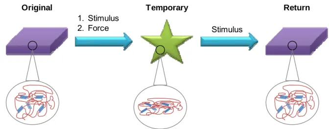
Figure 1.1: A cartoon demonstrating a shape memory cycle. A stimulus and force are applied to the original shape, and it is then fixed in its temporary shape. The material will remain in that temporary shape until the stimulus is reapplied, at which point it returns to its original shape. The insets show the semi-crystalline network during the shape memory cycle.
1.1.1 Shape Memory Materials for Biomedical Applications 1. Stimulus
2. Force Stimulus
3
The mechanical properties of SMPs vary based on the type of material and the
desired application. Because this thesis is focused on the development of biomaterials, this
review will be on materials for biological applications. There have been many reports of
using shape memory polymers for biological applications because of the plethora of
materials that are biocompatible and have good shape memory properties. Polymer
materials for biological applications should ideally be biocompatible, biodegradable, and
have similar mechanical properties to the surrounding tissue.
SMPs for biological applications are typically polyesters (e.g., poly(ε-caprolactone),
poly(alkyl adipates), polylactides, etc.) because of their general non-toxic and
biodegradability properties.5-10 Some interesting proposed applications include self-tying
sutures, stents, artificial muscles, and biosensors.5,6 Lendlein and Langer showed that SMPs
could be used for biodegradable self-tying sutures made from oligo(ε-caprolactone) and
2,2(4),4-trimethylhexanediisocyanate thermoplastics. These sutures are an alternative for
doctors who have to tie sutures internally (Figure 1.2A).9 Another interesting use of shape
memory polymers for biomedical applications was investigated by Gall and coworkers, who
designed an epoxy-based shape memory neural probe (Figure 1.2B). Here, the idea was to
initiate the shape transition after the probe was inserted into undamaged tissue (damaged
tissue reduces the effectiveness of the probe). Serrano et al. synthesized citric acid based
shape memory thermosets that had transition temperatures near body temperature and
tunable degradation rates and that could be used as drug delivery vehicles (for hydrophobic
4
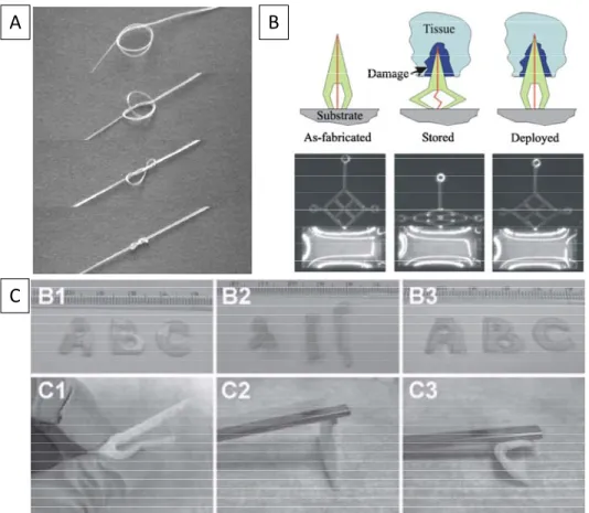
Figure 1.2:Applications of SMP materials. Image A shows a self-tying suture going from its temporary shape to its original shape; Image B shows a neural probe (rough 1 mm in size) going through its shape memory cycle and its potential to push itself beyond the damaged tissue; Image C shows the shape memory ability of a citric-acid-based polyester SMP.
1.1.2 Shape Memory Biomaterials on the Micro- and Nanoscales
The vast majority of the literature on shape memory materials utilizes materials on
the macroscopic level (> 1 mm actuations). However, there are several reports that
demonstrate the micro- and nanoscopic shape memory ability of common SMPs.12-22 Using
a poly(ethylene)-based SMP, Bae et al. were able to make materials with very small pitch
sizes using a two-step shape memory technique.18 They accomplished this by first stretching
the SMP film (above 90 °C) and then imprinting 400 nm lines (above 115 °C) to give the
temporary shape; then, when the material was heated to 90 °C, the film contracted, yielding
lines with a smaller pitch (Figure 1.3A). There have also been a few examples of
microscopic shape memory materials that show potential as dynamic cellular substrates.19-21
A
B
5
Our group, along with the Mather and Aoyagi groups, has demonstrated this potential using
poly(ε-caprolactone) with human mesenchymal stem cells19, a glassy SMP from the NOA-63
formulation (a polyurethane) with C3H/10T1/2 mouse embryonic fibroblasts20, and multi-arm
copolymers of poly(ε-caprolactone) with NIH 3T3 fibroblasts21. All three reports show that,
during the transition from a lined temporary shape to a flat original shape, cells transition
from an aligned to a random formation. Figure 1.3B shows an example from the Aoyagi
group.
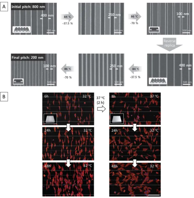
Figure 1.3: Shape memory on the micro- and nanoscales. (A) A two-way step polymer going from its first temporary shape (lines with a pitch of 800 nm and stretched bulk film) to
A
6
its second temporary shape with lines now pitched to 200 nm (no longer stretched).18 (B)
Cells that are cultured on shape memory substrates, showing that cell interact dynamically with the dynamic substrate.21
1.1.3 Chemical Versatility with Shape Memory Materials
The literature on SMPs contains extensive studies on the effects of various copolymers and
additives, but only a few reports have discussed chemical functionality in relation to
SMPs.22,23.Safranski and Gall examined the effects that the chemical structure and crosslink
density of various types of methacrylate side groups have on thermal, mechanical, and
shape memory properties.22 Xu and Song showed that the incorporation of an azide
functionality into polyhedral oligomeric silsesquioxane and polylactic acid networks allowed
for biofunctionalization of their materials (Figure 1.4).23 The authors did not discuss the
extent of functionalization or how the polymer properties were affected beyond the retention
of the mechanical properties, lowering of the Tg, slowing of the shape transition, and
fluorescence of the film (upon chemical attachment of a fluorescently labeled
alkyne-functionalized Arg-Gly-Asp-Ser). Due to its random incorporation into the network, the
amount of azide in the system could not be well controlled, and its inclusion was limited to
small amounts (without continued loss of thermal and mechanical properties).
7
Figure 1.4: Shape memory polymer system that contains a reactive functionality. (A) Scheme showing the addition of a small molecule azide and then functionalization. (B) The fluorescence of the film implies that there is some functionalization of the film.
1.2 Review of Shape Shifting and Shape Memory Particles 1.2.1 Techniques to Make Polymeric Particles
Much effort has been invested in the development of methods to produce particles of
various sizes and shapes from a wide range of materials.25-32 Common techniques such as
emulsion, precipitation, and soft lithography have produced a large library of polymeric
particles with different sizes, shapes, and compositions. Because the literature on
fabrication techniques is so vast, the focus will be on techniques relevant to this thesis,
developed in the DeSimone and Mitragotri groups.
Particle Replication in Nonwetting Templates (PRINTTM) is an extremely powerful
particle synthesis method to create monodisperse particles, developed by DeSimone and
coworkers.33-37 PRINTTM works by utilizing a photo-curable low-surface-energy fluoropolymer
to make nonwetting molds from silicon masters (which can vary widely in size and shape).
Using this low surface energy mold prevents the material (polymer, protein, etc.) from
staying on the surface between the particles. However, at the same time, the particle
material remains in the particle wells due to capillary action. The particles are then
harvested from the mold by using a “sticky” harvesting layer (such as a thin film of poly(vinyl
alcohol) on PET) to remove the particles from the mold (Figure 1.5A). This unique approach
has led to a variety of shapes (hexnuts, cubes, arrows, filaments, boomerangs, etc.) on
varied length scales (10 nm to 200 µm) (Figure 1.5B). This group has also performed some
interesting work using stretched PDMS masters to created stretched PRINTTM molds and
8
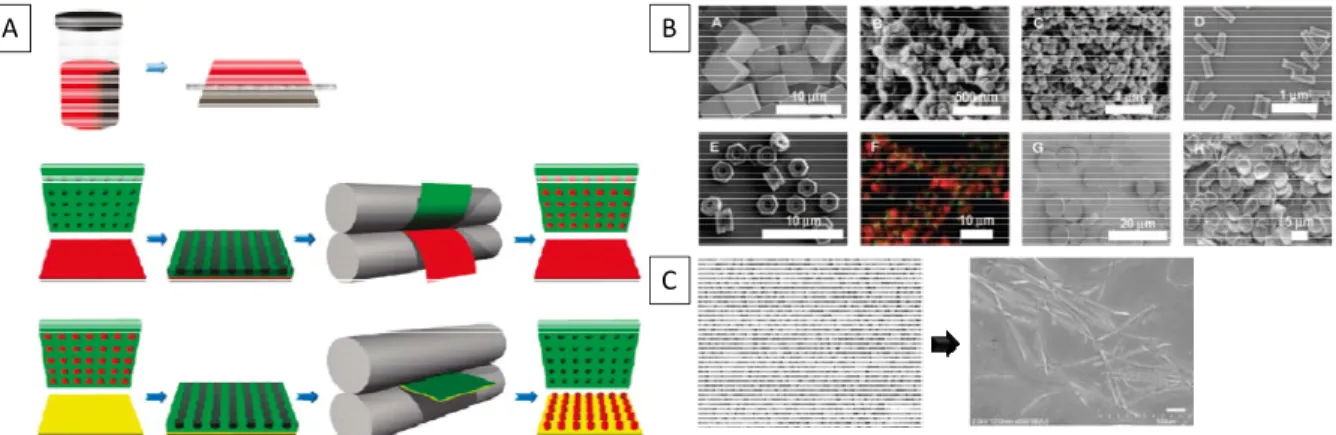
Figure 1.5: The PRINTTM process and the various particle shape and sizes this process can yield. (A) A thin film material (in solution or in a liquid phase, red) is first made. The PRINTTM film (green) is then applied to this film and run through a laminator to place the
material in the wells and remove excess material. The particles are then retrieved using a harvesting layer (yellow). (B) Shows particles of varying size, shape, and composition. (C) The left panel shows particles from the original mold and the resulting particles if the mold is initially stretched (4 times at 70% elongation each time).
The Mitragotri group has also developed an interesting method to produce particles
of different shapes.38 Here, particles are dispersed in a stretchable poly(vinyl alcohol) matrix,
exposed to heat and/or solvent, and then stretched in different directions to yield unique
shapes and sizes (Figure 1.6). While particles of various sizes and shapes were achieved,
this technique is not universal. Because this technique relies on the starting materials to
already be in particle form, some of the more unique shapes are limited to certain materials,
and the heavy use of solvents and heat are required to remove the particles from the matrix.
Regardless, this group has shown that, using this technique, they can easily study the effect
of particle shape in regards to biological applications.
A B
9
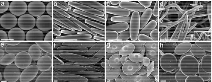
Figure 1.6: The above SEMs show the variety of available shape from Mitragotri's stretching method.
1.2.2 Importance of Particle Size and Shape
Size, shape, and surface chemistry are of critical importance for determining the
ultimate biodistribution, delivery, and bioactivity of particles.25-32 Over the past decade, there
have been many reports that exemplify this importance. For example, DeSimone and
coworkers examined poly(ethylene glycol) hydrogel particles of different sizes, shapes, and
surface chemistries produced by PRINTTM to illustrate how these properties affect cell
uptake.1 They found that HeLa cells were able to internalize particles as large as 3 µm, but
particles that were smaller (hundreds of nanometers) and had higher aspect ratios
(cylindrical) were much more readily internalized. The importance of aspect ratio was shown
in a report by Geng et al., in which the uptake and circulation time of spherical particles and
filaments were compared.31 They found, extraordinarily, that the flexible filament particles
were able to remain in circulation for up to a week (compared to a maximum of a day for
spherical particles), were less likely to be taken up by cells under flow, and—because of the
extended circulation time (preliminary results)—they were better able to reduce tumor size
over the course of a week (compared to free drug or spherical particles). Using their unique
method to make particles, Mitragotri et al. studied the ability of polystyrene particles to
10
particle dictates not only cellular response but how a cell initially encounters the particle—
there is a different cellular response if a cell contacts pointed end of a rice-shaped particle or
the long flat side initially (Figure 1.7).
Figure 1.7:The effect of size and shape on particle uptake. Top image shows the effect that different sized PRINTTM particles have on internalization; bottom image shows the effect
of particle shape (and initial contact) has on phagocytosis.
1.2.3 Shape Shifting Particles
There are clear advantages to a particle system that is capable of changing shape at
a particular time. To that end, there are several reports of shape shifting (not shape
memory) particles. Stimuli that induce shape changes include light41, pH42-44, DNA45, surface
tension and viscosity46, and swelling47. It is important to define the difference between shape
memory and shape shifting. Shape memory implies that there is control of the original and
temporary shapes, and the original shape is returned upon reapplication of the stimulus.
Shape shifting particles are much more confined in utility, in that one shape is always
beyond the control of the researcher, and either the temporary or the return must usually be
a sphere.
For example, Shi et al. were able to make shape shifting reversible nanoparticles
(spheres) by partially crosslinking and un-crosslinking a poly(3,4-dihydroxycinnamic acid-co -4-hydroxycinnamic acid) based system.41 They were able to increase and decrease the size
of their particles repetitively by ~200 nm by the shrinkage or extension of the particle matrix
1
11
(after irradiation by UV) when the cinnamic acid units cyclized or decyclized. Kozlovskaya et
al. made microsized hollow hydrogel shells that bulged somewhat reversibly by changing
from acidic to basic pH. The most interesting example is that of the shape shifting particles
developed by the Mitragotri group.46,47 Here, stretched polylactide-based particles would
become spherical when exposed to a stimulus (temperature, pH, or solvent) due to the
surface tension and viscosity of the stimulated material. They showed that this shape shift
altered how cells interacted with the particle: the particle would not be internalized until it
shape shifted into a sphere (Figure 1.8). The Mitragotri group also took advantage of
crosslinked particles, making “reversible” binary particles that change from one shape to
another by swelling and deswelling in favorable and non-favorable solvents. The above are
examples of shape shifting particles—not shape memory particles. To our knowledge, to
date, there are no reports of a true shape memory particle system.
Figure 1.8: Shape shifting PLGA particles going from rice shaped particles to spherical particles as they are exposed to increased temperature (A).46 The effect of this shape shift is
shown in (B), where the particle will not be internalized until a spherical morphology is achieved.47
1.2.4 Shape Shifting Particles with Shape Memory Transitions
While shape shifting particles are interesting, and there are no reported examples of
shape memory polymer particles that have defined original and temporary shapes, it is
A
12
worth identifying materials that could be considered shape memory particles—or rather use
transitions that could be called shape memory.48-50 Liquid crystalline shape memory
materials are, in ways, more akin to shape memory alloys than traditional shape memory
polymers because they go through a crystalline phase change. In the case of micro- and
nanoscale particles, this change results in micro- or nanoscopic sized changes in particle
size and shape. Yang et al. reported main-chain liquid crystalline polymer nanoparticles that
had a reversible shape memory transition from ellipsoidal shape (nematic stage) to a
spherical shape (isotropic).48 These materials are unique because the spherical shape is the
equilibrium state only when the material is in an isotropic stage (Figure 1.9A). Ohm et al.
utilized aluminum oxide porous membranes to make liquid crystalline actuators with rod
lengths of approximately 20 µm. This liquid crystalline pre-polymer (a calamitic three-core
mesogen with laterally fixed acrylate groups) was placed in an aluminum oxide template and
co-cured with hexanediol diacrylate.49 When rods were removed from the template they
would reversibly contract in size as they went from nematic to isotropic phases (Figure
1.9B). Haseloh et al. used a slightly modified crosslinked polyesters (made from diethyl
malonate derivatives and bis(hydroxyosyhexyl) bisphenyl derivatives) to make
shape-shifting particles that went from a spherical shape to irregular shapes as they were heated
from a the smectic A to isotropic phase (Figure 1.9C).50 Unlike previous examples, this
transformation was irreversible. Overall, while there are many examples of shape shifting
particles, and even some cases for which this shape shifting is reversible, there remains no
13
Figure 1.9: Shape shifting liquid crystalline particles. (A) The particles were heated to 101 °C (to their isotopic phase) and either flash cool with liquid nitrogen (left) or slowly cooled to room temperature (right).48 (B) Liquid crystalline actuator rods at room temperature
(i), heated to their isotropic stage (ii), and then cooled back to their nematic stage (iii).49 (C)
Crosslinked liquid crystalline elastomers that when heated (right) go from a spherical shape(left) to irregular shapes irreversibly (adapted from reference 50).
1.3 Review of CT Contrast Materials 1.3.1 Small Molecule Contrast Agents
Computed tomography (CT) has become an essential tool for everyday diagnosis of
numerous diseases and conditions. CT utilizes X-rays to visualize cross-sections of a patient, producing either a 2D or 3D image that shows variation in the density of the
surrounding tissue. The created image is an important diagnostic tool for discovering
anomalies, such as soft tissue tumors51 or atherosclerotic plaque.52 The quality of the
developed image is dependent on the electron density of the surrounding material. While the
difference in the density of muscle tissue versus bone is significant, the same cannot be
said of softer tissues (such as veins and arteries).53 To improve the visibility of soft tissue,
contrast agents, which contain atoms with high electron densities such as barium and
iodine, are often utilized.The most commonly used contrast agents are iodinated liquids that A
B
14
are administered intravenously shortly before an examination. These liquids can be
monomers (Ultravist®), dimers (VisipaqueTM), ionic (Renografin®), and nonionic
(OmnipaqueTM) (Figure 1.10).54
Figure 1.10: Structures of common contrast agents (left to right), Ultravist®, OmnipaqueTM, and VisipaqueTM.
These contrast agents are highly effective in increasing the contrast of softer tissues
around the patient’s body with few side effects in healthy patients; however, patients with
decreased kidney capabilities such as the elderly, patients with chronic with kidney disease,
and diabetics are at risk for contrast induced nephrotoxicity (CIN), which further reduces
renal function.55-57 Additionally, liquid commercial contrast agents lack specificity and exhibit
rapid extravasation from blood and lymphatic vessels (typical distribution half-life of
approximately 3 to 10 minutes).53,58 With a rapidly aging population, the need to develop
contrast agents that are safe for patients with decreased renal function has become
increasingly important.57
1.3.2 Nanocarriers of Small Molecule Contrast Agents and Iodinated Nanoparticles To circumvent issues commonly associated with commercial contrast agents, much
research has been conducted to develop novel contrast systems such as nanoscopic
carriers of small molecule contrast agents and novel polymeric structures containing
iodobenzenes. Nanosized particles have been shown to have increased circulation times in
comparison to iodinated liquids, and they are removed typically by the liver rather than the
kidneys.58 These attributes will allow patients who are at risk for CIN to be imaged without
15
surfactant stabilized crystalline particles64, and polymeric nanoparticles65,66. Liposomes have
been known for decades and have been FDA approved for some drug delivery applications,
making them appealing carriers for small molecule contrast agents. Samei et al. developed
a liposomal carrier for Iopamidol that allowed for imaging of vessels in a mouse breast tumor
with a resolution of 200 microns.60 Liposomes have also been of interest as multimodal
carriers for both CT and magnetic resonance (MR). Using OmnipaqueTM and an MR imaging
agent (Prohance®), Zheng not only showed that dual imaging was possible but was able to
obtain circulation times on the order of days (Figure 1.11).61 Nanoemulsions such as the
ones made by de Vries et al. have also shown increased circulation times and little in vivo toxicity.63 Specifically, they used a polybutadiene-PEG block copolymer to stabilize
emulsions of several iodinated oils, obtaining enhanced contrast for up to 3 hours. Stabilized
crystalline nanoparticles of an iodinated acryloxy ester have been used for detection of
macrophages in rabbits, which could aid in the diagnosis of infectious and autoimmune
diseases.64
Figure 1.11: Left shows micrographs of the resulting liposomes, and middle and right images show the contrast results for both CT and MRI. Figures adapted from reference (61).
Polymeric nanoparticles have also been used as nanocarriers. Particles with shells
of crosslinked poly(ethylene glycol)-poly(propylene glycol)-poly(ethylene glycol) and
Lipiodol® (iodinated poppy seed oil)-containing cores have been developed, and these
16
Similar systems have also been shown with polystyrene microsized particles, which were
swelled in the presence of 2,3,5-triiodobenzoylethyl ester.66
While small molecule carriers have the advantage of using materials that are already
approved for human use, they contain unbound small molecules that could potentially be
processed through the kidneys. Polymers that contain covalently bound iodine may
circumvent this issue. Iodine-containing polymers based on methacrylates67-69, anhydride
esters70, and cellulose71 have been reported. These materials incorporate iodobezene
derivatives either in the back bone or side groups on the polymer chain. Nanoparticles of
these polymers have similar properties to the small molecule carriers—longer circulation
times and clearance through liver and spleen. Aviv et al. showed that polymer nanoparticles
produced by the emulsion polymerization of 2-methacryloyloxyethyl(2,3,5-triiodobenzoate)
provided significant contrast enhancement after 30 minutes and allowed for the easy
visualization of a cancerous mouse liver (Figure 1.12).69
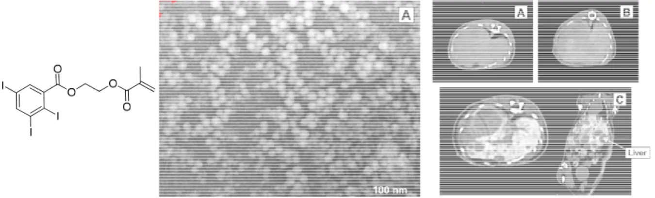
Figure 1.12: Left shows the structure of 2-methacryloyloxyethyl(2,3,5-triiodobenzoate); middle shows micrographs of the particles (roughly 50 nm in size); right shows CT scan before injection (A), after 3 minutes (B), and after 4 hours post injection. Figures adapted from reference (69).
A cellulose material containing covalently attached 2,3,4-triiodobenzoate in solution
was able to visualize the infra-renal aorta of a sheep, thus showing potential as a material to
treat cerebral aneurysms or arteriovenous malformations.71 While all of these developed
17
toxicity remains problematic.53 While there is variance in the structure and delivery method
of contrast agents, almost all iodine-based contrast agents described in the literature utilize
aromatic ring bound iodine. This structure is presumably employed to increase the stability
of the bound iodine, but aromatic bound iodine precursors are expensive and poorly
biodegradable. To our knowledge, there is only one example of a radiopaque
non-aromatically bound iodine contrast agent. This substance was designed mainly for flame
retardant purposes and contained a significant amount of the brominated precursor.57
Ideally, a contrast agent should be highly iodinated, biodegradable, biocompatible, long
circulating, and processable.
1.3.3. Metal-based Nanoparticle Contrast Agents
The main predictor of an atom’s contrasting ability is it’s atomic number (Z); the mass
attenuation coefficient, which governs an element’s contrast, is a function of Z3.72 As a
result, high-Z metals have generated significant interest as potential CT contrast agents,
and have been formulated as nanoparticles to prolong circulation in the body.58 The size of
metal nanoparticles can be precisely controlled, and they are fairly amenable to
biomodification, but only a few metals have proved suitable for this application based on
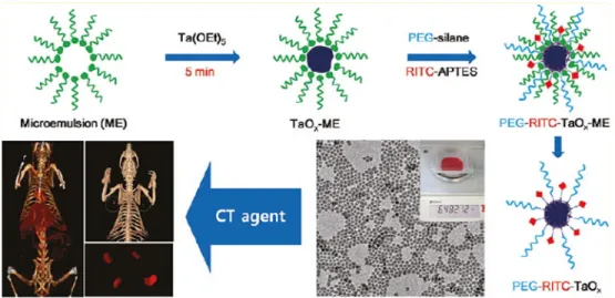
cost, toxicity, and radioactivity considerations.72,73 Recently Oh et al. have reported the
gram-scale synthesis of bioinert TaOx nanoparticles functionalized with a PEG-silane
derivative for use in CT imaging (Figure 1.13).74 The nanoparticles circulated in the blood for
18
Figure 1.13: Synthesis of the TaOx particles, TEM of particles, and the result of using these
particles in a mouse model.74
Rabin et al. have produced a PVP coated Bi2S3 nanoparticle that achieved significant
enhancement of the cardiac ventricles in Balb/c mice with a circulation time of >2 h and had
a prolonged blood half-life of 140 minutes, much longer than that of currently used clinical
formulations.59,75 Numerous groups have investigated Au-containing contrast agents and
have found appreciable success due to gold’s well-established biocompatibility and flexibility
in terms of size and functionalizability.72 Work performed recently by Sun et al. produced
gold particles suitable for CT imaging of cancer cells.76 The gold particles were
functionalized with glycol chitosan to facilitate enhanced stability and passive targeting of
tumor tissue through the EPR effect. In addition, research carried out by Alric et al. has
generated gold nanoparticles in which a gold nanoparticle is functionalized with gadolinium
chelates linked through disulfide bonds.77
The toxicity of metal nanoparticle CT contrast agents is unclear; a comprehensive
prospective toxicity study has not been performed.72 As a result, no metal-based contrast
19 References
1. Ratna, D.; Karger-Kocsis, J. J. Mater. Sci.2008, 43, 254-269.
2. Mather, P.; Luo, X.,Rousseau, I. Annu. Rev. Mater. Res. 2009, 39, 445–471. 3. Rousseau, I.; Mather, P. J. Am. Chem. Soc.2003, 125(50), 15300-15301. 4. Lendlein, A.; Jiang, H.; Junger, O.; Langer, R. Nature2005, 434, 879-882. 5. Rousseau, I. Polym. Eng. Sic. 2008, 48(11), 2075-2089.
6. Liu, C.; Qin, H.; Mater, P. T. J. Mater. Chem.2007, 17, 1543-1558.
7. Alteheld, A.; Feng, Y.; Kelch, S.; Lendlein, A. Angew. Chem. Int. Ed., 2005, 44, 1188-1192.
8. Li, F.; Hasjim, J.; Larock, R. J. Appl. Polym. Sci.2003, 90(7), 1830-1838 9. Lendlein, A.; R. Langer, Science2002, 296, 1673-1676.
10. Small et. al., IEEE., 2007, 54(6), 1157-1160.
11. Serrano, C.; Carbajal, L.; Ameer, G. A. Adv. Mater. 2011, 23, 2211–2215.
12. Altebaeumer, T.; Gotsmann, B.; Pozidis, H.; Knoll, A.; Duerig, U. Nano. Lett. 2008, 8, 4398-4403.
13. Liu, N.; Huang, W.; Phee, S.; Tong, T. Smart Mater. Struct.2008, 17, 057001-057007. 14. Nelson, B.; King, W.; Gall, K. Appl. Phys. Lett.2005, 86, 103108-103111.
15. Mazurek et al. (2008) Shape memory polymer articles with a microstructured surface,
US Patent App 2008/0027199.
16. Sherman et al. (2007) Methods for changing the shape of a surface of a shape
memory polymer article. PCT/US2007/073825.
17. Wang, Z.; Hansen, C.; Ge, Q.; Maruf, S. H.; Ahn, D. U.; Qi, H. J.; Ding, Y. Adv. Mater.
2011, 23, 3669–3673.
18. Bae, W. G.; Choi, J. H.; Suh, K. Y. Small2012, DOI: 10.1002/smll.201201554
20
20. Davis, K.A; Burke, K.A.; Mather, P.T.; Henderson, J.H. Biomaterials2011, 32, 2285-2293.
21. Ebara, M.; Uto, Koichiro, U.; Idota, N.; Hoffman, J.M.; Aoyagi, T. Adv. Mater. 2012, 24, 273-278.
22. Safranski, D.L.; Gall, K. Polymer2008, 49, 4446-4455.
23. Xu, J.; Song, J. Proc Natl. Acad. Sci. USA2010,107, 7652-7657.
24. Gratton, S. E. A.; Ropp, P. A.; Pohlhaus, P. D.; Luft, J. C.; Madden, V. J.; Napier, M. E.;
DeSimone, J. M. Proc. Natl. Acad. Sci.USA2008, 105, 11613. 25. Best, J. P.; Yan, Y.; Caruso, F. Adv. Healthcare Mater 2012, 1, 35.
26. Euliss, L. E.; DuPont, J. A.; Gratton, S.; DeSimone J.; Chem. Soc. Rev. 2006, 35, 1095. 27. Daum, N.; Tscheka, C.; Neumeyer, A.; Schneider M. WIREs Nanomed Nanobiotechnol
2012, 4, 52.
28. Decuzzi, P.; Pasqualini, R.; Arap, W.; Ferrari, M. Pharmaceutical Research 2009, 26, 235.
29. Zhang, K.; Fang, H.; Chen, Z.; Taylor, J. A.; Wooley, K. L. Bioconjugate Chem.2009, 19, 1880.
30. Geng, Y.; Dalhaimer, P.; Cai, S.; Tsai, R.; Tewari, M.; Minko, T.; Discher, D. E. Nat.
Nanotechnol. 2007, 2, 249.
31. Champion, J. A.; Mitragotri, S. Proc. Natl. Acad. Sci. U.S.A.2006, 103, 4930.
32. Rolland, J. P.; Maynor, B. W.; Euliss, L. E.; Exner, A. E.; Denison, G. M.; DeSimone, J.
M J. Am. Chem. Soc.2005, 127, 10096-10100.
33. Merkel, T. J.; Herlihy, K. P.; Nunes, J.; Orgel, R. M.; Rolland, J. P.; DeSimone, J. M.
Langmuir 2010, 26, 13086-13096.
21
35. Wang, Y.; Merkel, T. J.; Chen, K.; Fromen, C. A.; Betts, D. E.; DeSimone. J. M.
Langmuir, 2011, 27, 524.
36. Gratton, S. E. A.; Williams, S. S.; Napier, M. E.; Pohlhaus, P. D.; Zhou, Z.; Wiles, K. B.;
Maynor, B. B.; Shen, C.; Olafsen, T.; Samulski, E. T.; DeSimone, J. M. Acc. Chem. Res.
2008, 41, 1685–1695.
37. Champion, J. A.; Katare, Y. K.; Mitragotri, S. Proc. Natl. Acad. Sci. U.S.A. 2007, 104, 11901.
38. Hwang, D. K.; Oakey, J.; Toner, M.; Arthur, J. A.; Anseth, K. S.; Lee, S.; Zeiger, A.; Van
Vliet, K. J.; Doyle, P. S. J. Am. Chem. Soc. 2009, 131,4499. 39. González, E.; Arbiol, J.; Puntes, V. F. Science 2011, 334, 1377.
40. Shi, D. Matsusaki, M. Kaneko, T. Akashi, M. Macromolecules2008, 41, 8167-8172. 41. Na, K.; Bae, Y. H. Pharmaceut. Res2002, 19, 681-688.
42. Kozlovskaya, V.; Higgins, W.; Chen, J.; Kharlampieva, E. Chem. Commun.2011, 47, 8352-8354.
43. A. P. Griset et al.J. Am. Chem. Soc. 2009, 131, 2469-2471.
44. Chien, M.; Rush, A. M.; Thompson, M. P;. Gianneschi, N. C. Angew. Chem. Int. Ed.
2010, 49, 5076-5080.
45. Yoo, J.-W.; Mitragrotri, S. Proc. Natl. Acad. Sci. U.S.A. 2010, 107, 11205-11210. 46. Leea, K. J; Yoon, J.; Rahmani, S.; Hwang, S.; Bhaskar, S.; Mitragotri, S.; Lahann, J.
Proc. Natl. Acad. Sci. U.S.A. 2012, 109, 16057-16062
47. Haseloh, S.; Ohm, C.; Smallwood, F.; Zentel, R. Macromol. Rapid Commun.2011, 32, 88-93.
48. Yang, Z.; Huck, W. T. S.; Clarke, S. M.; Tajbakhsh, A. R.; Terentjev, E. M. Nat. Mater.
2005, 4, 486-490.
49. Ohm, C.; Haberkorn, N.; Theato, P.; Zentel, R. Small2011, 7, 194-198.
22
51. Hyafil, F.; Cornily, J.; Feig, J.; Gordon, R.; Vucic, E.; Amirbekian, V.; Fisher, E.; Fuster,
V.; Feldman, L.; Fayad, Z. Nature Medicine 2007, 13, 636-641. 52. Krause, W. Adv. Drug. Deliv. 1999, 37, 159-173.
53. Heinrich, M. C.; Häberle, L.; Müller, V.; Bautz, W.; Uder, M. Radiology2009, 250(1), 68-86.
54. Haller, C.; Hizoh, I. Invest. Radiol.2004, 39(3), 149-154. 55. Halvorsen, R. A. Radiology2008, 249(1), 9-15.
56. Katzber, R. W.; Barrett, B. J. Radiology2007, 243(3), 622-628.
57. Kong, W. H.; Lee, W. J.; Cui, Z. Y.; Bae, K. H.; Park, T. G.; Kim, J. H.; Park, K.; Seo, S.
W. Biomaterials2007, 28, 5555-5561.
58. Katzberg, R. W.; Haller, C. Kidney International2006, 69, S3-S7.
59. Samei, E.; Saunders, R. S.; Badea, C. T.; Ghaghada, K. B.; Hedlund, L. W.; Qi, Y.;
Yuan, H.; Bentley, R. C.; Mukundan, S. Int. J. Nanomed.2009, 4, 277-282.
60. Zheng, J.; Perkins, G.; Kirilova, A.; Allen, C.; Jaffray, D. A. Invest. Radiol. 2006, 41(3), 339-348.
61. Montet, X.; Pastor, C. M.; Vallée, JP.; Becker, C. D.; Geissbuhler, A.; Morel, D. R.;
Meda, P. Invest. Radiol.2007, 42, 652-658.
62. de Vries, A.; Custers, E.; Lub, J.; van den Bosch, S.; Nicolay, K.; Grüll, H. Biomaterials
2010, 31, 6537-6544.
63. Hyafil, F.; Cornily, J.; Feig, J.; Gordon, R.; Vucic, E.; Amirbekian, V.; Fisher, E.; Fuster,
V.; Feldman, L.; Fayad, Z. Nature Medicine 2007, 13, 636-641.
64. Kong, W. H; Lee, W. J.; Cui, Z. Y.; Bae, K. H.; Park, T. G.; Kim, J. H.; Park, K.; Seo, S.
W. Biomaterials2007, 28, 5555-5561.
23
68. Galperin, A.; Margel, S. J. Polym. Sci. Pol. Chem.2006, 44, 3859-3868.
69. Aviv, H.; Bartling, S.; Kieslling, F.; Margel, S. Biomaterials2009, 30, 5610-5616. 70. Carbone, A. L.; Song, M.; Uhrich, K Biomacromolecules2008, 9, 1604–1612.
71. Mottu, F.; Rüfenacht, D. A.; Laurent, A.; Doelker, E. Biomaterials2002, 23, 121-131. 72. Shilo, M.; Reuveni, T.; Motiei, M.; Popovtzer, R. Nanomedicine2012, 7(2), 257-269. 73. Yu, S.; Watson, A. D. Chem. Rev.1999, 99, 2353-2377.
74. Oh, M. H.; Lee, N.; Kim, H.; Park, S. P.; Piao, Y.; Lee, J.; Jun, S. W.; Moon, W. K.; Choi,
S. H.; Hyeon, T. J. Am. Chem. Soc.2011, 133, 5508-5515.
75. Rabin, O.; Perez, J. M.; Grimm, J.; Wojtkiewicz, G.; Weissleder, R. Nat. Mater.2006, 5, 118-122.
76. Sun, I.; Eun, D.; Koo, H.; Ko, C.; Kim, H.; Yi, D. K.; Choi, K.; Kwon, I. C.; Kim, K.; Ahn,
C. Angew. Chem. Int. Ed.2011, 50, 1-5.
77. Alric, C.; Taleb, J.; Le Duc, G.; Mandon, C.; Billotey, C.; Le Meur-Herland, A.; Brochard,
T.; Vocanson, F.; Janier, M.; Perriat, P.; Roux, S.; Tillement, O. J. Am. Chem. Soc.
Chapter II
CHEMICALLY AND PHYSICALLY DYNAMIC SURFACES
2.1 Introduction
Controllable surface properties such as surface energy and topography are extremely desirable. How a material interfaces with its environment is fundamental to its function; thus, research into the development of such materials has been extensive.1-6 This consideration is especially important for biomaterials because their surface energy and topography affect critical properties such as biocompatibility; cell growth, adhesion, alignment, and differentiation; biodegradation; and protein absorption. Dynamic control of these functions is even more attractive. Applications for such dynamic materials range from deployable materials (such as stents)7-9 to simulation of in vivo environments (cell signaling events)10 and biosensors11.
25
structure of these materials limits their ability to be chemically surface-modified without the loss of their thermal and mechanical properties. Thus, a truly versatile material capable of tunable and dynamic surface chemistry and topography has remained elusive.
Herein, we describe the material development, surface functionalization, and dynamic surface switching behavior of a material that enables true control of both its surface chemistry and topography. This was accomplished by designing a shape memory thermoset that contained a known shape memory polymer, poly(octylene adipate), and a novel and easily functionalizable polymer, poly(octylene diazoadipate). Adjusting the ratios of the two segments allowed for facile control of the transition temperature. Topographical actuation on multiple length scales (1 mm to 100 nm) was easily achieved, and the surface of the material was easily functionalized with a variety of alkynes (e.g., hydrophilic to hydrophobic and reactive to non-reactive) using copper assisted Huisgen [3+2]-cycloaddition (click chemistry). The combination of micro- and nanoscopic shape memory with surface functionalization produced materials that could tunably switch both their surface chemistry and topography as they transitioned through the shape memory cycle. These materials are therefore ideal substrates for scenarios in which control of the surface chemistry and topography is critical.
2.2 Experimental Methods
2.2.1 Materials
All materials were purchased from Sigma-Aldrich or Fisher Scientific unless otherwise noted. PRINT® molds were provided by the DeSimone group and used exclusively for surface embossment. Alkyne and Rhodamine B functionalized poly(ethylene glycol)s (PEGs) were synthesized according to previous literature procedures.25-28
2.2.2 Monomer and Polymer Characterization
26
Elmer Pyris 1 TGA (thermogravimetric analyzer) (TGA), and Waters gel permeation chromatography (GPC) system relative to polystyrene standards.
2.2.3. Film Characterization
All crosslinked films were characterized by DSC, TGA, Instron 5556 Universal Testing Machine (Instron), Perkin Elmer’s Pyris Diamond Dynamic Mechanical Analyzer, and bright field and fluorescence microscopy. Surface analysis of both the pre- and post-functionalized films were accomplished with Kratos Axis Ultra DLD X-ray Photoelectron Spectrometer (XPS), attenuated total reflectance Fourier transform infrared spectroscopy (ATR-FTIR) using a Bruker ALPHA FT-IR spectrometer, and water-in-air contact angles, which were measured with a KSV instrument and imaging using the sessile drop method (with at least 3 different films per functionality and 5 measurement per film). All SEMs were taken on a Hitachi S-4700 Cold Cathode Field Emission Scanning Electron Microscope. Raman experiments were performed with a Reinshaw Confocal Raman Spectrometer with a 735 nm wavelength laser.
27
hours and dried for 5+ hours at 80 °C.29 Attachment was confirmed by ATR-FTIR before the experiments. All samples were prepared in triplicate and averaged over 3 cycles.
2.2.4 Monomer and Polymer Synthesis
Synthesis of Diethyl 2,5-diazidoadipate. In a nitrogen purged flask, diethyl meso-2,5-dibromoadipate (12.67 g, 35.2 mmol) was added with sodium azide (9.15 g, 141 mmol). The solvent, 1:1 mixture of H2O and CH3CN was added. The reaction was allowed to stir at 25 °C for 24 hours. The product was extracted with ethyl ether, dried with MgSO4, and solvent removed. The monomer was used without further purification, yield 9.33 g (93%). 1H NMR, CDCl3, δ (ppm) 4.27 (q, J = 8 Hz, 4H), 3.91 (t, J = 4 Hz, 2H), 2.00 – 1.94 (m, 2H), 1.82 – 1.78 (m, 2H), and 1.32 (t, J = 8 Hz, 6H). 13C NMR, CDCl
3, δ 169.65, 61.82, 61.38, 27.46, and 13.94.
Copolymerization of 81:19 Diethyl 2,5-diazidoadipate and Adipic Acid. A dry flask was charged with diethyl 2,5-diazidoadipate (3.038 g, 10.7 mmol), adipic acid (6.655 g, 45.6 mmol), 1,8-octanediol (8.472 g, 57.9 mmol), and Novozyme 435TM lipase catalyst (1.82 g). The flask was nitrogen purged before heating the reaction to 80 °C. After 5 hours, vacuum was very pulled to 40 torr, and that pressure was maintained for 24 hours, at which time it was pulled to 3 torr for an additional 6 hours. The polymerization was terminated by dissolving the polymer in CHCl3, filtering, and precipitating in cold methanol (-78 °C). Final yield was 13.13 g (89%). 1H NMR, CDCl
3, δ (ppm) 4.17 (t, J = 6 Hz, 4H), 3.99 (t, J = 4 Hz, 18H), 3.89 (t, J = 4 Hz, 2H), 3.58 (t, J = 6 Hz, 1H), 2.27 (b, 18H), 1.93 – 1.91 (m, 2H), 1.79 – 1.76 (m, 2H), 1.63-1.55 (b, 44H), and 1.28 (b, 52H).
28
precipitation into cold methanol (-78 °C), and the prepolymer was dried in vacuum for 24 hours, yielding 4.89 g of polymer (98%). 1H NMR, CDCl
3, δ (ppm) 6.12 (s), 5.59 (s), 4.93 (m), 4.20 (t, J = 6 Hz, 4H), 4.05 (t, J = 8 Hz, 18H), 3.92 (t, J = 4 Hz, 2H), 3.50 (q, J = 5.3 Hz, 1H), 2.32 (t, 18H), 1.99 – 1.94 (m, 2H), 1.85 – 1.78 (m, 2H), 1.67-1.58 (b, 44H), and 1.32 (b, 52H).
2.2.5 Functional Shape Memory Material Development
PRINT® Embossing. A prepolymer solution containing approximately 2 wt% DEAP (2,2-diethoxyacetophenone) was cast into a mold and placed into a vacuum oven 70 °C for 1 hour at standard pressure and then 30 minutes under 100 torr. After this time, the PRINT® mold was carefully placed on the top of the hot film. While maintaining temperatures between 60 and 70 °C, the mold was placed a UV chamber for 10 minutes to cure the polymer in the PRINT® mold, creating the permanent shape. The PRINT® mold was gently removed before analysis of the patterned crosslinked film. The material’s temporary shape was developed by placing a PRINT® mold on top of the polymer film, sandwiching them between two glass slides, and placing them in a press with enough force to significantly depress the film. This setup was then placed in an oven at 70 °C for 1 hour before being placed in the freezer for at least 45 minutes to freeze in the temporary shape.
29
different solvents were used for propargyl glycine (water and pyridine, pH >7), propiolic acid (t-butanol and water, 1:1), and propargyl amine (t-butanol and water, 1:1).
Thin Shape Memory Films. Thin shape memory films were produced by first using a drawdown bar (#76) to make a thin film (less than 170 µm in thickness) of a pre-polymer solution (roughly a 20% solution with 2 wt% DEAP) on a sheet of PET. PRINTTM films (or none in the case of flat surfaces) were then applied to the thin film and another sheet of PET was placed on top before running the entire assembly through a laminator (temperature of 80 °C at a pressure of 80 psi). The top PET sheet was removed (or not, in the case of the flat films), then the films were UV crosslinked (10 minutes). The PRINTTM or PET films were removed and checked for consistency. The secondary shapes were obtained in a similar manner: the PRINTTM film was applied to the crosslinked film and run through the laminator (temperature of 80 °C at a pressure between 90 and 110 psi). Air was blown over the film as it came out of the laminator to initially cool, and the film was placed (with the PET or PRINTTM film still in place) in the freezer (< -5 °C) for at least 5 minutes. The PRINTTM film was removed, and the secondary shape was checked for consistency. Return shapes are easily achieved by heating the crosslinked polymer above its melting temperature (care should be taken to not heat excessively because excess heat can distort the PET substrate)
30
2.2.6 Cytotoxicity
The cytotoxicity of these materials was studied with HeLa and macrophage cell lines. The percent viability was found using a CellTiter-Glo® luminescent cell viability kit to determine the amount of bioluminescent ATP present in the cells after 3 days of incubation. Each measurement was performed in triplicate with three independently prepared batches of polymeric material that possessed non-featured, chemically modified, and non-modified surfaces.
2.2.7 Degradation
Degradation studies were performed for the non-embossed (flat) P77,23 copolymer and for the same polymer embossed with boomerang shapes. Films of known weight were placed in 1 mL of 0.01 M pH 7.4 phosphate buffered saline (PBS) solution at 37 °C. The films were removed from the buffer solution at prescribed intervals and dried under vacuum for 24 h before their masses were measured. Each measurement was performed on three separate samples. Mass loss (ML) was calculated according to the following equation, where mi is the initial mass and mf is the final mass,
100
i f im
m
m
ML
Water uptake (WU) was measured for P77,23 copolymer films placed in 0.01 M pH 7.4 PBS solution at 37 °C for prescribed intervals using the equations
100
d d swm
m
m
WU
100
)
(
i i swm
m
m
Abs
WU
31
2.3 Results and Discussion
2.3.1 Pre-Polymer Synthesis and Characterization
Polyesters were chosen to take advantage of the control they afford over monomer ratios, molecular weights, and end groups. Scheme 2.1 outlines the synthetic strategy chosen for the preparation of the dynamic substrates. The base material was a semicrystalline polyester that allowed for control of monomer ratios, molecular weights, end groups, and melting transition temperatures (i.e., switching temperature). To ensure mild reaction conditions for surface modification, azides were incorporated into the main polymer chain with the intent of utilizing the copper assisted click chemistry.30-34 Click chemistry is favorable for biological applications due to the general biocompatibility of many alkynes and azides, the ease of monomer synthesis, and the extensive library of commercially available alkynes.
The development of these azide-containing shape memory materials began by synthesizing the diazide monomer via substitution from the commercially available meso-2,3-dibromodiethyladipate in nearly quantitative yield. This monomer was copolymerized with adipic acid and 1,8-octanediol using a lipase catalyst to yield shape memory polymers with various copolymer ratios. Polyadipates are known SMPs, and in this system, poly(octylene adipate) is the sole contributor of shape memory properties.10
Scheme 2.1: Synthesis of azide-containing polyester.
O O O Br Br O O O O N3 N 3
O
HO OH
O
O NaN3, H2O/CH3CN (1:1)
+ +
O O
O N 3
N 3
O
Novozym 435 80oC, 48 h, 40 torr
HO OH
rt, 24 h
32
All copolymers had molecular weights between 11 and 20 kg/mol and polydispersities between 1.30 and 1.89. The thermal properties could be adjusted simply by controlling the feed ratio of the diester and the diacid monomers. When the ratio was varied from 0 to 45% diazide monomer incorporation, melting transitions were obtained between 19 to 67 °C, respectively (Table 2.1).
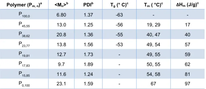
Table 2.1: Properties of the alcohol endcapped azide-containing shape memory polymers
Polymer (Pm, n)a <Mn>b PDIb Tg (° C)c Tm ( °C)c ΔHm (J/g)c
P100,0 6.80 1.37 -63 - -
P45,55 13.0 1.25 -56 19, 29 17
P38,62 20.8 1.36 -55 40, 47 40
P23,77 13.8 1.56 -53 49, 54 57
P19,81 12.7 1.73 - 49, 55 59
P17,83 9.7 1.89 - 50, 55 62
P15,85 11.6 1.24 - 54, 58 81
P0,100 23.1 1.59 - 67 97
a) The monomer ratios (m = diazide and n = adipic acid percent composition) were determined by 1H-NMR, b) measured by GPC with polystyrene standards, c) DSC, second heat 10°C/min, two melting points are typically observed for poly(alkyl adipate)-based polymers35
Endcapping with 2-isocyanatoethyl methacrylate of the most crystalline copolymers yielded the desired shape memory prepolymers (Scheme 2.2).
Scheme 2.2: Endcapping of azide-containing polyesters. O O O N3 N3 O O O O O O O
4 4 4 NH
O H N O O O O O n O O O N3 N3 O O O O O 4 4 n
CH2Cl2 16 h
O NCO