©IJRASET 2015: All Rights are Reserved
584
Voltage Stability Enhancement in SCIG Based
Wind Farm Using Facts with Unbalanced Fault
Mr.M.Vimalraj1, Mr.B.Alex2, Mr.P.Raghavendran3, Mr.D.Venkata Ramana4
1
Lecturer,TPEVRPC,Vellore,Tamil Nadu,India. 2,3
PG Student,Kingston Engineering College,Vellore,Tamil Nadu,India. 4
Assistant Professor, Kingston Engineering College,Vellore,Tamil Nadu,India.
Abstract-- The stability of fixed speed wind turbines can be improved by a STATCOM, which is well known and documented in literature for balanced grid voltage dips. Under unbalanced grid voltage dips the negative sequence voltage causes additional generator torque oscillations. In this paper investigations on a fixed speed wind farm with squirrel cage induction generators(SCIG) directly connected to the grid in combination with a STATCOM under unbalanced grid voltage fault are given by means of theory and simulations and also different kinds of control methods are discussed. The simulation results clarify the effect of positive and negative sequence voltage compensation by a STATCOM on the operation of a SCIG wind farm.
Keywords: Statcom, Voltage Stability, SCIG, Wind farm, low voltage Capability, STATCOM.
I. INTRODUCTION
Wind Energy is playing a key role on the way towards a sustainable energy future. Among the generator types used for wind turbines the technical development has moved from fixed speed to variable speed concepts. But still of fixed speed type using asynchronous generators directly connected to the grid.
During voltage dips the induction generators may consume a large amount of reactive power as their speed deviates from the synchronous speed, which can lead to a voltage collapse in the network. Different methods have been investigated to enhance the fault ride through capability like installation of a StatCom has been identified to provide the best dynamic stability enhancement [3]. A StatCom is a voltage source converter based device providing dynamic reactive power support to the grid. Thus, the StatCom can help to integrate wind power plants in a weak power system [4]. The StatCom can also perform an indirect torque control for the same kind of generators [7] to decrease the mechanical stress during grid voltage dip. All these investigations have covered balanced grid faults, but the majority of grid faults is of unbalanced nature.
The unbalanced-voltage problem can cause unbalanced heating in the machine windings and a pulsating torque leading to mechanical vibration and acoustic noise [8]. The StatCom control structure can be adapted to these unbalanced voltage conditions [9], and positive and negative sequence of the voltage can be controlled independently.
The paper is structured as follows. An analysis of the induction generators behavior under balanced and unbalanced grid voltage in section II is followed by the presentation of the proposed StatCom control structure in section III. Comparison of different control methods for stability analysis is described in section IV. In section V, a conclusion closes the paper.
II. TORQUE-SLIP CHARACTERISTIC OF INDUCTION
GENERATOR UNDER VOLTAGE DIP
Usually the wind turbine operates at nominal stator voltage in operation point A where the electromechanical torque is the same as the mechanical torque. When the stator voltage is reduced due to a grid fault the torque slip-characteristic changes. If the voltage dip is smaller the induction generator may resume a stable operation point C via B. But for a deep voltage dip the induction generator will deviate from point D to an instable operation. The induction generators may have to be disconnected from the grid due to over speed or there may be a voltage collapse in the network due to the high consumption of reactive power at higher slip. Under unbalanced grid voltage the steady-state electro-magnetical torque can be divided into positive and negative sequence torque [8] described by equations (1) and (2).
=
. , (1)
=
( ).( ) , (2)
where the positive and negative sequence torque Tp and Tn are a function of the positive and negative sequence rotor current
585
[image:3.612.206.420.157.351.2]used to calculate the torque ripple. To provide a graphical comparison the torque-slip characteristic of the machine for one specific acceleration process under a single phase to ground fault is taken from the simulation model and shown in Fig. 1. It becomes clear that the average torque is reduced due to the decreased positive sequence voltage and there is a high torque ripple due to the negative sequence voltage, which is also slip dependent. When the positive and negative sequence voltage can be controlled independently by a StatCom, the average torque and the torque ripple can also be controlled independently. A necessary StatCom control structure is presented in the next section
Fig 1. Simulated torque-slip characteristic for a single-phase to ground fault (1ph→0)
III. STATCOM CONTROL STRUCTURE
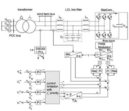
Fig 3. Proposed control structure of the StatCom to control positive and negative sequence voltage independently
[image:3.612.204.421.412.598.2]586
DC voltage and the positive and negative sequence of the voltage at the connection point of the StatCom. Therefore a precise sequence separation of the measured voltage into positive and negative sequence components is necessary, which is performed based on dual second order generalized integrators [15]. Using the sequence separation the positive and negative sequence of the voltage appear as DC values and can be controlled by PI controllers. To ensure a safe operation of the StatCom within its current capability the current references given by the four outer controllers must be limited to the maximum StatCom current. The priority is on the positive sequence reactive
Thus, the StatCom ensures the maximum fault ride through enhancement of the wind farm by compensating the positive sequence voltage. If there is a remaining StatCom current capability the StatCom is controlled to compensate the negative sequence voltage additionally, in order to reduce the torque ripple during the grid fault. The positive and negative sequence current references are added. Note, that the negative sequence currents references must be transformed into the positive rotating reference frame by a coordinate transformation with twice the grid voltage angle.
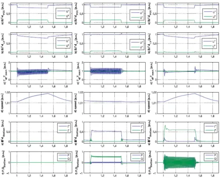
For the investigations under unbalanced grid fault different control targets will be compared to clarify the effect of positive or negative sequence voltage compensation on the operation of the induction generators. The target of the first method is to compensate the positive sequence voltage, while the negative sequence voltage will remain unchanged. The target of the second method is to eliminate the negative sequence of the voltage, while the positive sequence voltage will remain unchanged. Both methods are shown in the next section. In section III simulation results for a coordinated positive, negative sequence voltage control are shown.
Fig 3. Simulation results for operation during unbalanced grid fault (1ph → 50 %) without StatCom (left), with StatCom and
positive sequence voltage compensation (middle), with StatCom and negative sequence voltage compensation (right); a) positive and negative sequence voltage components at PCCb)positive and negative sequence voltage components at LV c) torque d) speed e) StatCom positive and negative current components f) StatCom P,Q
[image:4.612.93.528.286.640.2]©IJRASET 2015: All Rights are Reserved
587
here and thus the generator accelerates (see Fig. 3 right d)), leading to a continuous decrease in the positive sequence voltage component (see Fig. 3 right b)) due to the reactive power consumption. But the system does not reach the stability limit and the generator returns to nominal operation after the grid fault. Note that the drawback of the chosen StatCom control strategy in this case might be the oscillating active and reactive power of the StatCom (see Fig. 3 right f)).
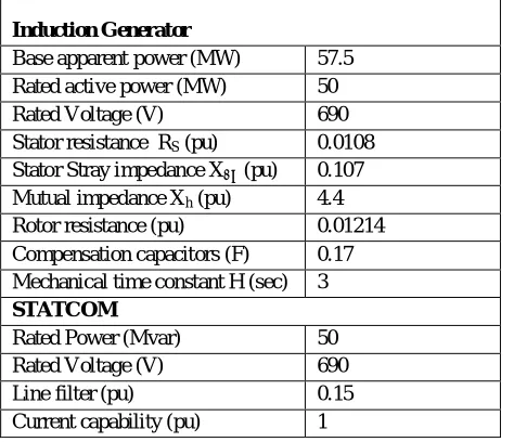
The results of this section enhance the understanding of the voltage control performed by the StatCom and the resulting operation of the induction generators. By compensating the positive sequence voltage the torque capability of the induction generators is increased and an acceleration during grid voltage dips can be decreased or avoided. By compensating the negative sequence voltage (the unbalanced component of the voltage) the torque oscillations of the induction generators can be decreased or avoided. The capability of the StatCom to compensate a voltage component depends on the chosen current rating of the StatCom and the impedance of the power system. For a high current rating of the StatCom and a weak power system (with high system impedance) the voltage compensation capability of the StatCom is also high. All power system parameters are given in TABLE I.
TABLE- I INDUCTION GENERATOR AND STATCOM PARAMETER
Induction Generator
Base apparent power (MW) 57.5 Rated active power (MW) 50 Rated Voltage (V) 690 Stator resistance RS (pu) 0.0108
Stator Stray impedance XSσ (pu) 0.107
Mutual impedance Xh (pu) 4.4
Rotor resistance (pu) 0.01214 Compensation capacitors (F) 0.17 Mechanical time constant H (sec) 3
STATCOM
Rated Power (Mvar) 50 Rated Voltage (V) 690 Line filter (pu) 0.15 Current capability (pu) 1
[image:5.612.190.427.241.445.2]IV. COMPARISON OF STABILITY ENHANCEMENT
TABLE III
VALUES OF INDEXES FOR DIFFERENT STABILIZATION METHODS
Index Pitch BR STATCOM SMES W/o
Cont roller
Voltage (p.u.sec)
1.73 0.32 0.26 0.22 4.46
Speed (p.u.sec)
0.48 0.02 0.02 0.02 7.81
Power (p.u.sec)
2.86 0.10 0.18 0.16 4.63
Angle (degsec)
75.04 56.4 48.54 46.00 103.0 5
588
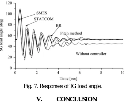
[image:6.612.199.420.204.333.2]performance of the SMES is the best, and the STATCOM is better than the BR. The pitch method exhibits the worst performance with respect to all indices.
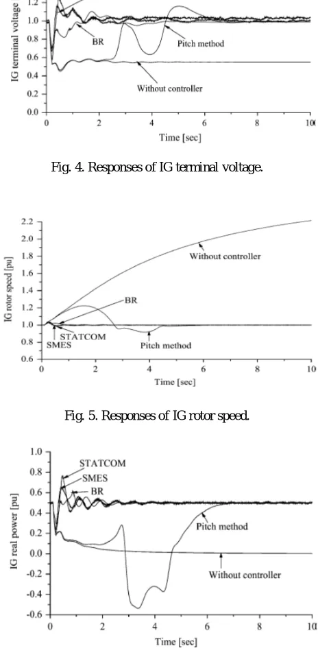
[image:6.612.191.423.229.708.2]Fig. 4 shows the responses of the IG terminal voltage. It is seen that the IG terminal voltage returns back to its steady state value due to the use of any of the devices of the SMES, STATCOM, BR, and pitch controller. Fig. 5 shows the responses of the IG rotor speed. It is seen that because of the use of any of the devices of the SMES, STATCOM, BR, and pitch controller, IG becomes stable. Fig. 6 shows the responses of the IG real power. In this case it is seen that any of the devices of the SMES, STATCOM, BR, and pitch controller can maintain the IG real power at the rated level. Fig. 7 shows the responses of the SG load angle. However, although each of the devices of the SMES, STATCOM, BR, and pitch controller can make the wind generator stable, it is evident from the simulation results that the performance of the SMES & STATCOM are the best. But compared with cost, SMES is higher and STATCOM is lower.
Fig. 4. Responses of IG terminal voltage.
Fig. 5. Responses of IG rotor speed.
[image:6.612.201.424.555.702.2]589
Fig. 7. Responses of IG load angle.
V. CONCLUSION
The proposed structure controls the positive and negative sequence of the voltage independently with priority on the positive sequence voltage. Thus, the StatCom ensures the maximum fault ride through enhancement of the wind farm by compensating the positive sequence voltage. A voltage control structure for a StatCom at a Fixed Speed Wind Farm under unbalanced grid voltage condition has been analyzed. If there is a remaining StatCom current capability the StatCom is controlled to compensate the negative sequence voltage additionally, in order to reduce the torque ripple during the grid fault. Hence the positive component is used to improved the voltage stability and negative component is reduces the torque oscillation of the induction generator. Then the life span of the generator parts are increases. Different methods of control techniques are analyzed with validation simulations.
REFERENCES
[1] E. W. E. A. European Wind Energy Association, “Powering europe:wind energy and the electricity grid,” Nov 2010.
[2] M. Tsili and S. Papathanassiou, “A review of grid code technicalrequirements for wind farms,” Renewable Power Generation, IET, vol. 3,no. 3, pp. 308-332, Sept. 2009.
[3] M. Ali and B. Wu, “Comparison of stabilization methods for fixed-speed wind generator systems,” Power Delivery, IEEE Transactions on,vol. 25, no. 1, pp. 323 -331, jan. 2010.
[4] C. Han, A. Huang, M. Baran, S. Bhattacharya, W. Litzenberger, L. Anderson, A. Johnson, and A.-A. Edris, “Statcom impact study on the integration of a large wind farm into a weak loop power system,” Energy conversion, IEEE Transactions on, vol. 23, no. 1, pp. 226-233, March 2008.
[5] L. Xu, L. Yao, and C. Sasse, “Comparison of using svc and statcom for wind farm integration,” Power System Technology, 2006. PowerCon 2006. International Conference on, pp. 1-7, Oct. 2006.
[6] M. Molinas, J. A. Suul, and T. Undeland, “Low voltage ride through
of wind farms with cage generators: Statcom versus svc,” PowerElectronics, IEEE Transactions on, vol. 23, no. 3, pp. 1104-1117, May 2008. [7] J. Suul, M. Molinas, and T. Undeland, “Statcom-based indirect torque control of induction machines during voltage recovery after grid faults,”Power Electronics, IEEE Transactions on, vol. 25, no. 5, pp. 1240 -1250, may 2010.
[8] E. Muljadi, D. Yildirim, T. Batan, and C. Butterfield, “Understanding the unbalanced-voltage problem in wind turbine generation,” in Industry Applications Conference, 1999. Thirty-Fourth IAS Annual Meeting.Conference Record of the 1999 IEEE, vol. 2, 1999, pp. 1359 -1365vol.2.
[9] C. Hochgraf and R. Lasseter, “Statcom controls for operation with unbalanced voltages,” Power Delivery, IEEE Transactions on, vol. 13,no. 2, pp. 538 -544, apr 1998.
[10] C. Wessels, S. Grunau, and F. Fuchs, “Current injection targets for a statcom under unbalanced grid voltage condition and the impact on the pcc voltage,” in EPE Joint Wind Energy and T&D Chapters Seminar 2011, April 2011.
[11] P. Rodriguez, G. Medeiros, A. Luna, M. Cavalcanti, and R. Teodorescu,“Safe current injection strategies for a statcom under asymmetrical grid faults,” in Energy Conversion Congress and Exposition (ECCE), 2010 IEEE, sept. 2010, pp. 3929 -3935.
[12] P. Rodriguez, A. Luna, G. Medeiros, R. Tedorescu, and F. Blaabjerg,“Control of statcom in wind power plants based on induction generators during asymmetrical grid faults,” in Power Electronics Conference(IPEC), 2010 International, june 2010, pp. 2066 -2073.
[13] A. Luna, P. Rodriguez, R. Teodorescu, and F. Blaabjerg, “Low voltage ride through strategies for scig wind turbines in distributed power generation systems,” in Power Electronics Specialists Conference, 2008.PESC 2008. IEEE, june 2008, pp. 2333 -2339.
[14] Kundur, Power System Stabiliy and Control. McGraw Hill, 1994.
590
VI. BIOGRAPHIES
Mr.M.Vimalraj received B.E(Electrical & Electronics Engineering) from Ganadipathy Tulsi’s Jain Engineering College, Vellore (TN), India in 2011 and he is currently a PG student in Power Systems Engg from Kingston Engg College, Vellore (TN), India. Areas of interest are include Renewable Energy Resources, Electrical machines, FACTS, Soft Computing.
Mr.B.Alex received B.E(Electrical & Electronics Engineering) from GanadipathyTulsi’s Jain Engg College, Vellore (TN), India in 2013 and he is currently a PG student in Power Systems Engg from Kingston Engg College, Vellore (TN), India. His Areas of interest are include Renewable Energy Resources, Electrical machines, FACTS.
Mr.P.Raghavendran received B.E(Electrical & Electronics Engineering) from GanadipathyTulsi’s Jain Engg College, Vellore (TN), India in 2014 and he is currently a PG student in Power Systems Engg from Kingston Engg College, Vellore (TN), India. His Areas of interest are include Renewable Energy Resources, Electrical machines, FACTS.
Mr.D.Venkata Ramana received B.E(Electrical Engineering) from