Technology (IJRASET)
Hybrid Isolated Wind–Hydro System by Using
Induction Generators and Battery Storage
Anant Chavan1, Prof.D.S. Chavan2
1
M.Tech Student Department of Electrical Engineering, 2Associate Professor Department of Electrical Engineering
1,2
Bharati Vidyapeeth Deemed University, College of Engineering, Pune, India
Abstract— Now a days Most of natural energy sources such as wind, geothermal, solar, biomass, and hydro show predominance for energy production. Out of these natural energy sources, small wind and small hydro energy which are complements each other. induction generators (SCIGs) is used to Power generation by wind as well as hydro systems. The wind turbine in recent year which has switched from fixed variable speed as later has advantages of 1) dynamically balance for power pulsations,torque 2) reduce in mechanical stresses,3) improves power quality 4) system efficiency. There are however some isolated locations where hydro and the Simultaniously exist the given wind potential but these cannot connected to thepower station i.e. Grid. For these locations , a “innovative isolated hydro wind hybrid system by using battery storage and cage generators” is presented in this paper. It employs two SCIG out of these two SCIG; One squirrel-cage induction generator (SCIG) is drive by a wind turbine having variable-speed and other SCIG driven along with constant-power hydro turbine BESS which feeds loads having four leg three phase system. To achieved maximum power tracking (MPT) Control technique is implemented for the VSCs . under variable wind speed using wind turbine with the help of rotor speed we can achieve maximum power. We can achieve it with controlling load voltage and frequency.Bidirectional power flow control is proposed in this paper.this proposed system analysis we did with the help of variable load and variable speed wind speed.
Keywords— Battery energy storage system (BESS), squirrel cage Induction generator (SCIG),small hydro, wind-system energy conversion (WECS).
I. INTRODUCTION
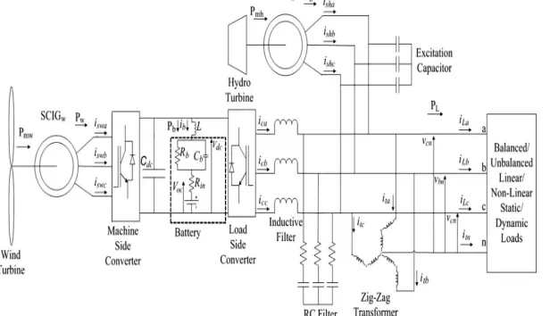
[image:2.612.162.470.516.693.2]II. SYSTEMDESCRIPTION In case of individual systems which is supplying local loads there are two possible cases
If wind system power is larger than load requirement then excess power is stored in battery.
When the power supplied from system which is less than the load in this case stored power from batteries transferring to the load side.
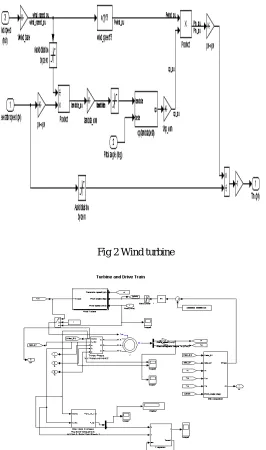
[image:3.612.176.442.257.707.2]In this independent systems, the control of voltage and frequency (VFC) is extremely important. battery-based controller is proposed control of frequency and voltage in isolated WECS . A novel current control technique is proposed for the load side converter. For generation of switching pulses to the converter reference current signal is generated from load side current as well as current generated from SCIG.By this control method, To get SCIG currents unbiased and the sinusoidal at the nominal frequency ,the switching of the load-side converter is proposed. With the help of zigzag transformer. load current is compensated using this converter. Fig 2 shows wind turbine Matlab model.
Fig 2 Wind turbine
Technology (IJRASET)
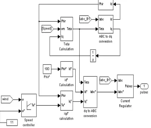
Fig4 control policy for the converter control at machine (SCIGw) side is given
III. CONTROLALGORITHM
Main objective of the converter of (SCIGw) machine side is to achieve MPT and to supply the essential of the SCIGw currents for
magnetization. To maintain load voltage frequency and magnitude we are using load side converter.for the two converter control technique is proposed in this paper.
A. control technique for machine side convrter
[image:4.612.155.460.90.349.2]The purpose of the converter which is (SCIGw)machine side is for MPT to achieved optimum of the torque for SCIGw to the current is given the required magnetizing to the SCIGw. The control policy for the converter control at machine (SCIGw) side is given in Fig. 4. The PWM Current-controlled inverter is operates as a three-phase sinusoidal current source. For generation of torque Te* speed of generator ω which is compared to the reference ω* and the error is given to PI controller.
fig 5 produce a torque Te*.
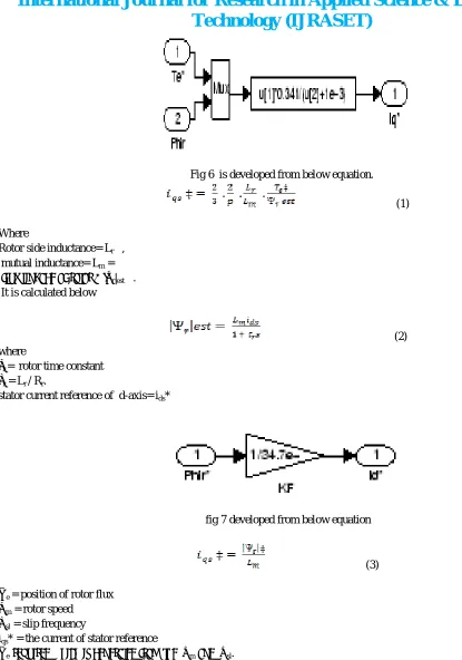
iqs* = reference stator quadrature-axis current .
Fig 6 is developed from below equation.
(1)
Where
Rotor side inductance= Lr ,
mutual inductance= Lm =
flux linkage of rotor = |ψr|est .
It is calculated below
(2) where
τr = rotor time constant
τr = Lr / Rr.
[image:5.612.53.468.49.641.2]stator current reference of d-axis= ids*
fig 7 developed from below equation
(3)
Θe = position of rotor flux
ωm = rotor speed
ωsl = slip frequency
iqs* = the current of stator reference
Technology (IJRASET)
Fig 8 developed from below equation
(4)
The value of ωsl which is calculated from iqs* the given motor parameters.
(5)
fig 9 shows the coordinate transformation model developed in Matlab.
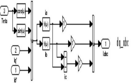
B. abc to dq transformation
Direct-axis and quadrature axis iqs* and ids* are converted into ia*, ib*, ic*.this three phase current is used as reference current for
pulse generation.To maintain the motor speed with required reference speed PI controller is need.
Fig 11 shows the coordinate transformation model developed in Matlab.
C. The Control of Load-Side Converter
To maintain frequency and voltage at the load side irrespective of load, load side inverter is proposed. balanced power in the system is achieved by
1) Extra power is stored in device like battery .
2) If there is extra power need to load side then that excess power is taking from load side
3) to maintain the constant value of the load load-side converter provides reactive power.The load side converter control scheme is given in fig 12.
4) The voltages reference (V*an, V*bn, V*cn) these load voltages control at time t V*an =√2Vtmsin(2πft) (6) V*an =√2Vm sin(2πft-2*pi/3) (7) V*an =√2Vm sin(2πft +2*pi/3) (8)
Where
f = frequency= 50 Hz,
Vm = 240 V.= the neutral to phase load voltage (rms)
The (van, vbn, vcn) load voltages are detected. They are compared with the voltages reference. This error voltages such as (vanerr,vbnerr and vcnerr) which are calculated as below
(9)
(10)
(11)
The SCIGh currents which are three phase currents (I*ah , I*bh, I*ch) which is reference which are generated by feed the error signals for voltage to Proportional Integral voltage controller. Which are calculated as
(13)
(14)
(15)
Where
Kpv= PI controller gain
Kiv = PI controller gain
The currents of three-phase SCIGh which are reference are characterized with the sensed currents of SCIGh. The current of SCIGh of the errors are given as
(16)
Technology (IJRASET)
(18)
by gain K=5 current errors are amplified. A fixed-frequency of 10 kHz repeating sequence having amplitude one is compare with above signals to get switching pulses for IGBTs of converter at the load-side.
[image:8.612.118.508.123.370.2]Fig12 :Load side converter
Fig14 diagram hybrid system in simulation
IV. RESULT
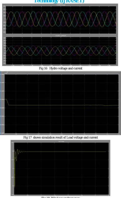
The overall performance of the hybrid system which is verified in the various dynamic conditions . under unbalanced and balanced linear load , balanced/unbalanced nonlinear load , analysis of the system is done using matlab simulink tool. Fig 13 shows simulation result showing WIND generation voltage and current:
Technology (IJRASET)
Fig 16 Hydro voltage and current
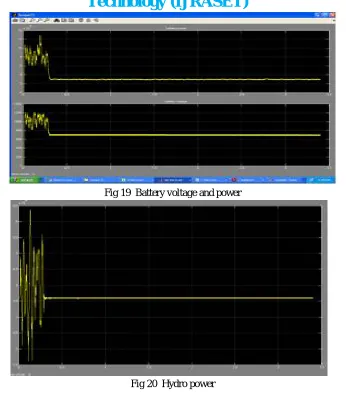
[image:10.612.117.506.65.701.2]Fig 19 Battery voltage and power
Fig 20 Hydro power
V. CONCLUSIONS
Small hydro energy and The energy of wind having the capacity to give balanced condition to each other. many more remote places are there and they cannot be connected to the grid and for these locations, four leg three phase Inverter independent hybrid system of wind-hydro which has been simulated by the use of commonly used block and and power system blocks tool boxes in MATLAB. This system uses SCIG which is driven by wind turbine and other SCIG which is driven by hydro turbine in parallel with BESS. In the proposed hybrid system the performance which is studied for variable wind speed and variable load. Our proposed hybrid system gives performance well under diverse dynamic conditions at the same time constant voltage and frequency is maintain.
VI. ACKNOWLEDGMENT
The authors would like to acknowledge the management of Bharati Vidyapeeth Deemed University College of Engineering, Pune for providing academic and technical support throughout this research work. Authors would also like to thanks to Mr.R.M.Holmukhe M-tech co-ordinator of Electrical Engineering Department, Pune and Dr.D.S.Bankar, Head of Electrical Engineering Department, Bharati Vidyapeeth Deemed University College of Engineering, Pune. Authors would also like to thanks Prof. Rahul Desai, Mr. Pradip Mandake BVDU College of Engineering, Pune. For his support.
REFERENCES
[1] Datta. S. Chavan; Pooja Kulhari; Nehal Kadaganchi; P. B. Karandikar; Puneet Singh; Rajesh Giri ‘Prediction of power yield from wind turbines for hilly sites‘Future Energy Electronics Conference (IFEEC), 2015 IEEE 2nd International Year: 2015
[2] Datta. S. Chavan; P. B. Karandikar ‘Linear Model of Flicker Due to Vertical Wind Shear for a Turbine Mounted on a Green Building’Artificial Intelligence with Applications in Engineering and Technology (ICAIET), 2014 4th International Conference on Year: 2014
Technology (IJRASET)
shear’Power Engineering and Optimization Conference (PEOCO), 2014 IEEE 8th International Year: 2014[4] Datta. S. Chavan; S. D. Bhide; P. B. Karandikar’Effect of vertical wind shear on flicker in wind farm’Global Humanitarian Technology Conference: South Asia Satellite (GHTC-SAS), 2013 IEEEYear: 2013
[5] Datta. S. Chavan; P. B. Karandikar; Abhay Kumar Pande; Santhosh Kumar’Assessment of flicker owing to turbulence in a wind turbine placed on a hill using wind tunnel’Circuit, Power and Computing Technologies (ICCPCT), 2014 International Conference on Year: 2014
[6] L. L. Lai and T. F. Chan, Distributed Generation: Induction and Permanent Magnet Generators. West Sussex, U.K.: Wiley, 2007, ch. 1.
[7] E. D. Castronuovo and J. A. Pecas, “Bounding active power generation of a wind-hydro power plant,” in Proc. 8th Conf. Probabilistic Methods Appl. Power Syst., Ames, IA, 2004, pp. 705–710.
[8] B. Singh, S. S. Murthy, and S. Gupta, “An improved electronic load controller for self-excited induction generator in micro-Hydel applications,” in Proc. IEEE Annu. Conf. Ind. Electron. Soc., Nov. 2003, vol. 3,pp. 2741–2746.
[9] J. B. Ekanayake, “Induction generators for small hydro schemes,” IEEE Power Eng. J., vol. 16, no. 2, pp. 61–67, 2002.
[10] M. Molinas, J. A. Suul, and T. Undeland, “Low voltage ride through of wind farms with cage generators: STATCOM versus SVC,” IEEE Trans. Power Electron., vol. 23, no. 3, pp. 1104–1117, May 2008.
[11] S. Ganesh Kumar, S. Abdul Rahman, and G. Uma, “Operation of selfexcited induction generator through matrix converter,” in Proc. 23rd Annu. IEEE APEC, Feb. 24–28, 2008, pp. 999–1002.
[12] G. Quinonez-Varela and A. Cruden, “Modelling and validation of a squirrel cage induction generator wind turbine during connection to the local grid,” IET Gener., Transmiss. Distrib., vol. 2, no. 2, pp. 301–309,Mar. 2008.
[13] E. Diaz-Dorado, C. Carrillo, and J. Cidras, “Control algorithm for coordinated reactive power compensation in a wind park,” IEEE Trans. Energy Convers., vol. 23, no. 4, pp. 1064–1072, Dec. 2008.
[14] L. Tamas and Z. Szekely, “Modeling and simulation of an induction drive with application to a small wind turbine generator,” in Proc. IEEE Int. Conf. Autom., Quality Test., Robot., May 22–25, 2008, pp. 429–433.
[15] A. Luna, P. Rodriguez, R. Teodorescu, and F. Blaabjerg, “Low voltage ride through strategies for SCIG wind turbines in distributed power generation systems,” in Proc. IEEE Power Electron. Spec. Conf., Jun. 15–19, 2008, pp. 2333–2339.
[16] M. Elnashar, M. Kazerani, R. El Shatshat, and M. M. A. Salama, “Comparative evaluation of reactive power compensation methods for a standalone wind energy conversion system,” in Proc. IEEE Power Electron. Spec. Conf., Jun. 15–19, 2008, pp. 4539–4544.
[17] B. Fox, D. Flynn, L. Bryans, N. Jenkins, D. Milborrow, M. O’Malley, R. Watson, and O. Anaya-Lara, Wind Power Integration Connection and System Operational Aspects. London, U.K.: IET, 2007, ch. 3.
[18] S. S. Murthy, B. Singh, P. K. Goel, and S. K. Tiwari, “A comparative study of fixed speed and variable speed wind energy conversion systems feeding the grid,” in Proc. IEEE PEDS, Nov. 2007, pp. 736–743.
[19] G. Poddar, A. Joseph, and A. K. Unnikrishnan, “Sensorless variable speed controller for existing fixed-speed wind power generator with unity-power-factor operation,” IEEE Trans. Ind. Electron., vol. 50, no. 5, pp. 1007–1015, Oct. 2003.
[20] M. G. Simoes, B. K. Bose, and R. T. Spiegel, “Fuzzy-logic-based intelligent control of a variable speed cage machine wind generation system,” IEEE Trans. Power Electron., vol. 12, no. 1, pp. 87–95, Jan. 1997.
[21] D. Joshi, K. S. Sindhu, and M. K. Soni, “Constant voltage constant frequency operation for a self-excited induction generator,” IEEE Trans.Energy C [22] L. A. C. Lopes and R. G. Almeida, “Wind-driven induction generator with voltage and frequency regulated by a reduced rating voltage source inverter,” IEEE
Trans. Energy Convers., vol. 21, no. 2, pp. 297–304, Jun. 2006.
[23] B. Singh and G. K. Kasal, “Voltage and frequency controller for a three-phase four-wire autonomous wind energy conversion system,” IEEE Trans. Energy Convers., vol. 23, no. 2, pp. 505–518, Jun. 2008.
[24] L.-R. Chen, R. C. Hsu, and C.-S. Liu, “A design of a grey-predicted Li-ion battery charge system,” IEEE Trans. Ind. Electron., vol. 55, no. 10, pp. 3692–3701, Oct. 2008.