International Journal of Emerging Technology and Advanced Engineering
Website: www.ijetae.com (ISSN 2250-2459, UGC Approved List of Recommended Journal, Volume 8, Issue 2, February 2018)314
Design and Implementation of an Arduino-based
Root-Zone Temperature control system
Morice O. Odhiambo
1, Wang Xiao Chan
1, 2*, Pessane Ivan Jaime de Antonio
1, Shi Yi Yan
1, Zhao Bo
11
College of Engineering, Nanjing Agricultural University, No.40 DianJiangTai Road, Pukou District, Nanjing, Jiangsu, China
2
Jiangsu Province Engineering Laboratory for Modern Intelligent Facilities in Agricultural Technology & Equipment, Nanjing 210031, China, No.40 DianJiangTai Road, Pukou District, Nanjing, Jiangsu, China Abstract—Low ambient air temperature experienced during
winter and early spring in Southern China expose plants to cold stress in an unheated greenhouse. Cold stress results in growth inhibition and an acute reduction in productivity in greenhouse plants, but due to the high energy consumption and costs, most of the greenhouses remain unheated. The few heated greenhouses usually result in environmental degradation from high consumption of non-renewable energy sources. In an attempt to find a simple and affordable solution to this problem that plagued small-scale farmers in this region, this study was undertaken.
Recent studies have shown that manipulation of the root-zone temperature of plants can improve the general plant health and appreciate productivity even though the above-soil portions are exposed to environmental stresses. Therefore, in this study, an Arduino-based root zone temperature (RZT) control system was designed and implemented to investigate the possibility of successful cultivation of pepper plants in an unheated greenhouse. The pepper plants were cultivated under cold stress in the RZT control system which encompassed an Arduino microcontroller, RZT acquisition module, RZT display module, switch module and heating module. The findings demonstrate that the system sustained the growth and development of pepper plants from the vegetative stage to the reproductive stage. A theoretical comparison of the power consumption of a conventional unitary system of greenhouse heating to the carbon fiber metal alloy heating boards revealed that the estimated output per hour of the conventional unitary systems required to maintain the greenhouse at the desired set-point temperature under extreme weather conditions was 96.31% higher than that for the heating boards. In conclusion, the RZT control system provided a simple, affordable and cost-effective method of growing greenhouse crops under cold stress in the Yangtze River Delta area of Southern China, offering the possibility of low energy consumption with high crop productivity. In addition, it provided a pollution-free alternative technique that could possibly substitute conventional greenhouse heating systems.
Keywords—Arduino microcontroller, Cold Stress, Root Zone Temperature, Root Zone Heating, Yangtze River Delta area of Southern China.
Abbreviations—RZT: Root Zone Temperature, GRP: Glass-Reinforced Plastics
I. INTRODUCTION
Winter and early spring in Southern China are often characterized by low ambient air temperature that results in the exposure of plants to cold stress in an unheated greenhouse. Cold stress has a severe effect on photosynthesis, plant enzyme activity, plant metabolism and plant fresh, dry matter accumulation [1-3]. This consequently leads to growth inhibition and an acute reduction in productivity in plants in an unheated greenhouse. However, due to the high energy costs, most of the greenhouses in this region usually remain unheated during winter and early spring. Conventional greenhouse heating systems in China involves usage of non-renewable energy sources such as coal and petroleum. High consumption of these energy sources produces high amounts of CO, CO2, SO2 and NOwhich are chronic air
pollutants [4, 5], therefore the few heated greenhouses usually result in environmental degradation. In addition, the poor degree of automation in majority of heated greenhouse results in massive heat wastage and uneven heat distribution within the greenhouse[6]. The ever increasing costs of these energy sources and the resulting detrimental environment effects of their usage, has brought into focus the need for the development of a simple, affordable, efficient and sustainable greenhouse heating systems. One of the proposed techniques is root zone heating.
International Journal of Emerging Technology and Advanced Engineering
Website: www.ijetae.com (ISSN 2250-2459, UGC Approved List of Recommended Journal, Volume 8, Issue 2, February 2018)315
Studies have shown that root zone heating can enhance plant growth, development and productivity[9-11], and reduce energy consumption[12]. In addition, the root-zone has a higher specific heat capacity as compared to the above-soil portion. This property of root zone provides the possibility of accurate, direct, simple manipulation and regulation of the temperature of the root-zone area[13] In the wake of intelligent control systems, Arduino has been extensively applied as a PID controller due to its reliability, simplicity, ease of use and ability to provide high control efficiency[14]. Also, its compatibility in interfacing with computing programs for instance LabVIEW and MATLAB makes Arduino the first choice microcontroller in many applications. Arduino has been used in a wide range of practical applications; robotics and image processing[15], wireless sensor networks[16-18], bioelectrical impedance analysis[19], computer numerical control[20], baby incubators[21] and health monitoring applications[22], GPS/GPRS vehicle monitoring and tracking systems[23-25] smart home control[26, 27], water level control in process industry[28], smart irrigation systems[29] and temperature control systems[30, 31]. Due to the attractions that Arduino offer as a decision control tool, an Arduino-based PID controller was selected to be used in the RZT control system.In this research, an Arduino-based RZT control system was designed and implemented to provide the necessary RZT conditions to perform growth and chlorophyll fluorescence characteristic investigations. The system encompassed an Arduino microcontroller, RZT acquisition module, RZT display module, Switch module, keypad module, data storage module and heating module. The system was able to achieve data acquisition by collecting RZTs from multiple points within the root zone, processing, control and achieved the established control indexes and display of RZTs. The design provided a simple, affordable, flexible and cost effective system. In addition, it provided a pollution-free alternative technique that could substitute conventional greenhouse heating systems.
In the past two decades, studies have been carried out on techniques of growing greenhouse plants during winter in Southern China. Some of the studies carried out assessed LED light supplementation[32], but a small fraction focused root zone temperature heating. Hence, this research purposed to find a solution that encompassed root zone heating, thus the design and testing of a root-zone temperature control system.
The findings could provide an understanding of a viable, simple, and cost-effective technique of successfully growing greenhouse crops during winter in Southern China.
II. MATERIALS AND METHODS
A. Experimental Setup and Test Material
The experiment and the system was set-up in a 2-ridge Venlo-type, an unheated greenhouse located at the College of Engineering of Nanjing Agricultural University, Nanjing, Jiangsu Province of China (118º 46´ N, 32º03´E). The study was carried out between 27th December 2016 and 19th June 2017. The test material was Pepper (Sujiao No. 5) seedlings that were transplanted into the cultivation bed on 27th of December, 2017. The cultivation bed was divided into four RZT treatments; CK-Control group, T20- 20°C RZT, T25-25°C RZT and T45-45°C RZT.
B. Overall System Design
International Journal of Emerging Technology and Advanced Engineering
Website: www.ijetae.com (ISSN 2250-2459, UGC Approved List of Recommended Journal, Volume 8, Issue 2, February 2018)316
C. System Hardware Design
1) Controller Module
[image:3.612.364.564.155.311.2]The Arduino UNO is a microcontroller whose operating principle is based on reading sensor values, making logical choices and decisions and transmitting the required signals to the actuators[33]. The Arduino Uno R3 (Arduino, China) applied in this study had an ATMEGA328P-PU processor used with an ICSP; In Circuit Serial Programmer. The technical specifications of the Arduino UNO R3 are; Operating Voltage 5V, Input Voltage limits 6V-20V, Digital I/O Pins 16 of which 6 pins (3, 5, 6, 9, 10, 11) provide PWM output, Analog Input Pins were 6, DC Current per I/O Pin was 40 mA, DC Current for 3.3V Pin was 50 mA and Flash Memory 512 KB, SRAM 96 KB, EEPROM 0 KB, Clock Speed 16 MHz[34].
Fig.1a Block diagram of the root zone temperature control system.
[image:3.612.25.280.370.519.2]The Arduino UNO has two power plugs; the USB power plug and the separate power plug that is used to supply
Fig.1b Schematic Diagram of the root-zone temperature control system.
power through an external power source. The Digital pins (0, 1) are labeled 0; RX and 1; TX, and they are serial in and serial out pins. GND pins were 3; input voltage pin was one, 5V pin was one, 3.3V pin was one, one reset push-button, and AREF pin was one. Core module circuit of the ATMEGA328P-PU processor is as shown in Fig. 2a
and the Arduino UNO board is as shown in Fig. 2b;
PB0/ICP1/CLKO/PCINT0 10
PB1/OC1A/PCINT1 11
PB3/MOSI/OC2A/PCINT3 13
PB2/SS/OC1B/PCINT2 12
PD6/AIN0/OC0A/PCINT22
8 PD5/T1/OC0B/PCINT21
7 PD4/T0/XCK/PCINT20
2 PD3/INT1/OC2B/PCINT19
1 PD2/INT0/PCINT18
28 PD1/TXD/PCINT17
27 PD0/RXD/PCINT16
26
PB4/MISO/PCINT4 14
PB5/SCK/PCINT5 15
PB7/TOSC2/XTAL2/PCINT7 6
PB6/TOSC1/XTAL1/PCINT6 5
PC6/RESET/PCINT14 25
PC5/ADC5/SCL/PCINT13 24
PC4/ADC4/SDA/PCINT12 23
PC3/ADC3/PCINT11 22
PC2/ADC2/PCINT10 21
PC1/ADC1/PCINT9 20
PC0/ADC0/PCINT8 19
AVCC
16 AREF
17
PD7/AIN1/PCINT23 9
ATMEGA328P IO7
IO6 IO5 IO4 IO3 IO2 IO1
IO0 IO8
IO9 IO10 IO11 IO12 IO13
AD0 AD1 AD2 AD3 AD4 AD5 RESET AREF
+
5
V
SS MOSI MISO SCK
+5V
LED & Reset
RXD TXD IO10
IO11 IO12 IO13
IO13 IO0
IO1
AD0 AD1 AD2 AD3 AD4 AD5
IO14 IO15 IO16 IO17 IO18 IO19
RESET
ATMEGA 328P
Fig. 2a Core module circuit of the ATMEGA328P-PU processor
ARDUINO MICROCONTROLLER DATA
ACQUISITION MODULE
SWITCH MODULE
RZT HEATING MODULE
RZT DISPLAY MODULE DATA
STORAGE MODULE KEYPAD MODULE
[image:3.612.324.563.460.657.2]International Journal of Emerging Technology and Advanced Engineering
Website: www.ijetae.com (ISSN 2250-2459, UGC Approved List of Recommended Journal, Volume 8, Issue 2, February 2018) [image:4.612.66.265.145.286.2]317
Fig. 2b: Arduino UNO Board: Arduino UNO board showing 16digital pins, 6 analog pins, and other various parts[14]
2) RZT Acquisition Module
The data acquisition module realized collection of RZT data and transmitted this to the controller module for analysis and processing. The sensor selected for the RZT acquisition module was the Sensirion SHT10 soil temperature sensors (Sensirion, Switzerland). In total 4 SHT10 sensors were used in the system.
Sensirion SHT10 Soil Temperature and Humidity; The SHT10 is a special soil temperature and humidity sensor. The sensor element and the signal processing element are integrated into a single unit that produces a digital output signal. The sensor includes a capacitive moisture sensitive components, temperature measuring element made by polymerization with energy gap material and 14 A/D converter and serial interface circuit to realize seamless connection. Therefore this product has a super-fast response, strong anti-jamming ability, high performance-to-price ratio. The 2-wire serial interface and internal voltage regulation, make the peripheral system integration rapid and simple.
Operating Conditions of Sensirion SHT10; the sensor is generally stable within the recommended normal operating range. Exposures to operating conditions outside the normal range for long periods of time can result in damage to the sensor. The SHT10 soil temperature sensor selected had the following technical specifications; Power supply voltage 2.4V-5.5V, with a recommended supply voltage of 3.3V, Temperature range -40°C to +123.8°C, Temperature measurement accuracy ±0.3°C to 0.5°C @ 25°C, Moisture range 0% to 100% RH, Humidity measurement precision ±1.8% to 4.5%RH @ 25°C and Power Consumption at sleep 2 μW, measuring 3 mW and an average value 90 μW at on 12bit measurement per second[35, 36].
Communication of the Sensirion SHT10 with the Microcontroller; The SHT 10 sensor has a total of four pins: two communication pins; DATA and SCK, and two Power pins; GND and VDD. The VDD supply voltage and GND is the GND pin. The Serial Clock input (SCK) synchronizes the communication between the microcontroller and the SHT 10 sensor. As the interface entails a fully static logic, there is no minimum SCK frequency. The serial data (DATA) pin is a bidirectional pin used in sending data in and out of the sensor. The data wires DATA of the SHT 10 were connected to the IO2, IO4, IO6 and IO8 and pins of the microcontroller to enable data transmission between Arduino and the SHT 10 sensor. The clock wires SCK of the SHT 10 were connected to the IO3, IO5, IO7 and IO9 pins of the Arduino to facilitate clock synchronization.
3) Root Zone Temperature Display Module
International Journal of Emerging Technology and Advanced Engineering
Website: www.ijetae.com (ISSN 2250-2459, UGC Approved List of Recommended Journal, Volume 8, Issue 2, February 2018)318
Fig.3 THM320 Recording Instrument showing real-time RZTs4) Data Storage Module
After the processing and analysis of RZT data by the Arduino microcontroller, the data is stored by the data storage module. The data storage module comprises of the Adafruit Data Logger Shield (Arduino, China). The Data logger Shield had SD card interface that worked with FAT16 or FAT32 formatted cards. It also features a built-in 3.3V level shifter circuitry that facilities fast read/write and prevents damage to the SD Card. It also features a real time clock (RTC) with coin cell battery backup keeps the time going even when the Arduino is unplugged. The data logger shield applies the R3 layout I2C and ICSP/SPI ports, hence it is compatible with a diverse variety of Arduinos and Arduino-compatibles [37, 38].
The Adafruit Data Logger Shield is as shown in Fig.4.
Fig.4: Adafruit Data Logger Shield
5) Switch Module
The switch module switches Off/On the current to the heating module. It the consisted of relays. Relays are automatic switches that uses a uses a small amount of current to drive a large current. In operation, the Arduino
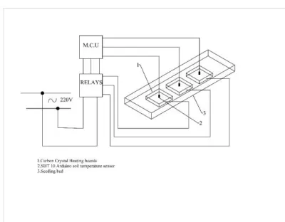
sends a signal that drives the relays to switch on/off the current to the heating module. The relay selected for the system was JQC-3FF-S-Z, 5V, 4 –Channel relay (Tongling, China). This relay required a 50mA-60mA driver current and was equipped with a high current relay of AC 250V 10A; DC 30V 10A and indication LEDs for relay output status that is usually on when the relay is in operation. This relay has four input signals and corresponding groups of 4 normally-open and normally-closed outputs. In the high current relay, input voltages of 5 V, 12 V or 24 V can be selected. When a signal is transmitted to an input from the Arduino, the corresponding output is normally-open. When there is no signal to input the relay, then the corresponding output is normally-closed. The relay is stable in performance, easy to use and install. In total three relays were used in the system. The relays were connected to the IO4, IO15 and IO16 pins of the microcontroller. A circuit diagram of the connection between the Arduino and the relay is shown in Fig.5.
R
e
a
y
B
u
ff
e
r
RL1
5V
RL2
5V
IO16 IO15
AC
WM1 AC
WM2
240V AC
AC
RL3
5V
IO14 AC
WM3
Fig.5 Proteus Capture the circuit diagram of the Arduino and the relay
6) Power Consumption Measurement
Power consumption was measured by DW-85 (CW Electronic Instrument Co.), digital single phase wattmeter. The wattmeter measured the power consumed by the carbon-fiber metal alloy heating plates. The wattmeter had the following technical specifications; Range of 0.001KWh to 99999KWh, Input Voltage of 0V to 300V, Input Current of 0A to 5A and a resolution of 0.2%FS.
7) Heating Module
International Journal of Emerging Technology and Advanced Engineering
Website: www.ijetae.com (ISSN 2250-2459, UGC Approved List of Recommended Journal, Volume 8, Issue 2, February 2018) [image:6.612.374.512.122.302.2]319
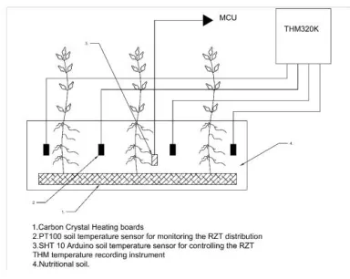
The carbon fiber-metal alloy heating boards had a power rating of 50-100W. As three RZT treatments were required to carry out the experiments, a total of three carbon fiber-metal alloy heating boards were used in the experiment. A thin transparent plastic film covered the top end of the cultivation bed in order to maintain temperature within the bed. A cross-sectional schematic diagram of the Carbon fiber-metal alloy heating boards and cultivation bed is as shown in Fig.6.Fig. 6 Cross-sectional schematic diagram of the Cultivation Bed and Carbon fiber heating board
8) Connection of Hardware Devices
After selection of the hardware components, the components of the controller, data storage and switch modules were installed in a control box and circuit connections were made. The control box provided a support that allowed for the mounting of the controller module and the switch module. In addition, the control box could be locked to prevent unauthorized operation of the controller module. Holes were drilled on the sides of the control box to provide access for the Arduino board power supply cables, connection of the SHT 10 sensors to the Arduino and the connections of the relays to the heat module. The hardware components installed in the control box mainly included the Arduino board and Adafruit data logger shield, and the relays. The internal connections of the control box were as shown in Fig.7.
Fig. 7: The Internal Connections of the Control Box
D. System Software Design
The system software design entailed root zone temperature measurement and control. The Arduino Uno board was programmed with the Arduino software by connecting the board to a computer via a USB port. Arduino boards have an integrated development environment (IDE) an open-source software based on Processing, avr-GCC, and other open-source software environments[39]. C programming language was used to write the control algorithm in the Arduino IDE and then uploaded onto the Arduino using a laptop computer via a USB port.
1) Control Algorithm
[image:6.612.85.277.259.412.2]International Journal of Emerging Technology and Advanced Engineering
Website: www.ijetae.com (ISSN 2250-2459, UGC Approved List of Recommended Journal, Volume 8, Issue 2, February 2018)320
2) Simulation
The control algorithm was developed and Proteus Design Suite 8.7 was used to simulate the algorithm on a virtual circuit before it is downloaded and implemented on the Arduino microcontroller.
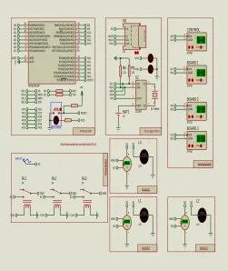
[image:7.612.326.577.133.431.2]The schematic model of the peripheral modules circuit connection with Atmega328P was captured using Proteus and is as shown in Fig. 8;
Fig. 8: Program Flow Chart
III. RESULTS
A. Greenhouse Abiotic Parameters
During the period of the research, ambient air temperatures within the greenhouse, frequently dropped to below zero. The average ambient air temperature was 16.96°C and the ambient temperature ranged from -2.66°C to 43.01°C. The root zone temperatures traced the desired trajectory pattern as managed by the Arduino. Actual ambient air daytime and night-time temperature variations within the greenhouse are shown in Fig 9a and the actual RZT variations were as in Fig.9b.
B. Plant Growth and Development Characteristics
The RZT control system was able to successfully sustain the growth and development of pepper plants from the vegetative stage to the reproductive stage during winter
PB0/ICP1/CLKO/PCINT010 PB1/OC1A/PCINT111 PB3/MOSI/OC2A/PCINT3PB2/SS/OC1B/PCINT213 12 PD6/AIN0/OC0A/PCINT22 8PD5/T1/OC0B/PCINT21 7PD4/T0/XCK/PCINT20 2PD3/INT1/OC2B/PCINT19 1PD2/INT0/PCINT18 28PD1/TXD/PCINT17 27PD0/RXD/PCINT16 26 PB4/MISO/PCINT414 PB5/SCK/PCINT515 PB7/TOSC2/XTAL2/PCINT76 PB6/TOSC1/XTAL1/PCINT65 PC6/RESET/PCINT1425 PC5/ADC5/SCL/PCINT1324 PC4/ADC4/SDA/PCINT1223 PC3/ADC3/PCINT1122 PC2/ADC2/PCINT1021 PC1/ADC1/PCINT920 PC0/ADC0/PCINT819 AVCC 16AREF 17 PD7/AIN1/PCINT23 9 ATMEGA328P IO7 IO6 IO5 IO4 IO3 IO2 IO1 IO0 IO8 IO9 IO10 IO11 IO12 IO13 AD0 AD1 AD2 AD3 AD4 AD5 RESET AREF + 5 V SS MOSI MISO SCK +5V
LED & Reset
RXD TXD IO10 IO11 IO12 IO13 IO13 IO0 IO1 AD0 AD1 AD2 AD3 AD4 AD5 IO14 IO15 IO16 IO17 IO18 IO19 RESET ATMEGA 328P SCK MISO SS S D C a rd CS DI DO CLK M1 SD MOSI VBAT 3 X11 X22 SCL 6 SDA 5 SOUT 7 U2 DS1307 1 2 32.768kHz SCL SDA BAT1 3V AD5 AD4 R5 2.2k R6 2.2k IO8
Data Logger Shield
http://www.adafruit.com/products/1141
IO14 IO15
Temp & Humidity
R e a y B u ff e r
BOARD 2 BOARD 3
80.0 11.0 %RH > °C DATA 2SCK 3 CONTROL SHT10 80.0 89.0 %RH > °C DATA 2SCK 3 BOARD 1 SHT10 84.0 30.0 %RH > °C DATA 2SCK 3 BOARD 2 SHT11 IO5 IO4 IO7 IO6 IO9 IO8 RL1 5V RL2 5V IO16 IO15 AC WM1 AC WM2 240V AC AC L1 12V L2 12V +88.8 W WM1 B2 B2 B2 +88.8 W WM2 B3 B3 B3 BOARD 1 L3 12V +88.8 W WM3 B1 B1 B1 84.0 30.0 %RH > °C DATA 2SCK 3 BOARD 3 SHT10 IO3 IO2 RL3 5V IO14 AC WM3
Fig.8:Circuit connection of Atmega328P and peripheral modules
in Southern China, achieving the objective of successfully growing plants under cold stress in an unheated greenhouse.
Fig.10a shows the cultivation bed with seedlings of pepper plants at the beginning of the study, and Fig.10b shows the cultivation bed with flowering pepper plants at the end of the study.
C. Power Consumption
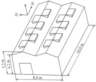
The greenhouse was made of aluminum alloy and glass. The greenhouse was 16m in length, 8m in width and 5.2m in height with a total floor area of 128 m2 and total surface square area of 455.6 m2.The glass was 4 mm in thickness. The greenhouse structure was as shown in Fig. 11. During summer and autumn seasons, the primary energy source of the greenhouse is solar radiation. Conversely, in winter and early spring, there is need to supplement the heat acquired from solar energy, especially at night when temperatures frequently drop to below 0°C.
Start
System Initialization
SHT10 Initialization & RZT Acquisition
Arduino RZT data processing
Adafruit data logger shield data storage Parameter comparison
with set-point values
Equal?
Output control signal to the relays
N
[image:7.612.90.269.249.475.2]International Journal of Emerging Technology and Advanced Engineering
Website: www.ijetae.com (ISSN 2250-2459, UGC Approved List of Recommended Journal, Volume 8, Issue 2, February 2018) [image:8.612.210.446.153.274.2]321
Fig. 9a: Ambient daytime and night-time air temperatures within the greenhouse over the experimental period
Control 20°C 25°C 45°C
Fig. 9b: Actual root zone temperatures of the different RZT treatment groups over 11 weeks of the experimental period
[image:8.612.176.468.302.485.2]
International Journal of Emerging Technology and Advanced Engineering
Website: www.ijetae.com (ISSN 2250-2459, UGC Approved List of Recommended Journal, Volume 8, Issue 2, February 2018) [image:9.612.70.256.183.343.2]322
Fig. 11: Dimensional structure of the solar greenhouseIn the theoretical analysis of a solar greenhouse, heat loss calculation is the most important step in determining the output of the heating system required to maintain the greenhouse at the desired set-point temperature under extreme weather conditions. The rate of heat loss,ԚGRP
from the greenhouse is calculated by Equation 1[40]
ԚGRP=[A1/R1 +A2/R2 +…](Ti-T0 )(fW )(fC )(fS ) Eqn. 1
GRP surface area of greenhouse =455.6 m2, and Thermal resistance of GRP =0.16m2°C. W-1[41]. The optimum ambient air temperature growing conditions for pepper plants ranges between 21°C to 27°C and temperatures below 12°C or above 30°C introduces an environmental stress on the plant[42, 43]. Thus for the purposes of this calculation, an ambient set-point temperature of 25°C is selected setting the temperature inside the greenhouse, Ti =
25°C. According to the Chinese Meteorological Administration (CMA), the lowest temperature recorded in Pukou District of Nanjing City during the period of the experiement was -4°C, thus the temperature outside the greenhouse under extreem conditions, TO was -4°C . A
wind velocity of 5.5ms-1 at 15m was also recorded[44] Assuming Construction type factor (fC) =1.08, System
factor (fS) =1.00, Wind factor (fW) =1.35, the average
heating load of the solar greenhouse used in this study was obtained to be 120.4 kW at design conditions.
The day and night time average heating load of the carbon fiber-metal alloy heating boards was recorded by
wattmeters and is shown in Fig.12.
IV. DISCUSSION
The average night-time power consumption for the RZT 40℃ carbon fiber-metal alloy board was 2.01 KWhr, and the average value for the RZT 25℃ carbon fiber-metal alloy board was 1.06 KWhr. Each board was 50cm*50cm and was able to successfully sustain the growth and development of four pepper plants from the vegetative stage to the reproductive stage under cold stress in an unheated greenhouse.
A theoretical comparison of a conventional unitary system of greenhouse heating to the carbon fiber-metal alloy heating boards was calculated. An assumption was made that both systems were applied in maintaining a suitable temperature environment for 150 plants within the greenhouse in this study for an hour under extreme weather conditions. The RZT 25℃ heating board was applied in this theoretical evaluation. The theoretical calculations revealed that the estimated output per hour of the conventional unitary systems required to maintain the greenhouse at the desired set-point temperature under extreme weather conditions was 96.31% higher than that for the heating boards. This evidently showed that the power consumption for root zone heating is significantly lower and more efficient in comparison to conventional unitary systems.
V. CONCLUSION
In this study, an Arduino-based root-zone temperature control system was designed and implemented.
1) The system was able to successfully sustain the growth and development of pepper plants from the vegetative stage to the reproductive stage during winter in Southern China, thereby finding a solution for horticulture cultivation in an unheated greenhouse.
International Journal of Emerging Technology and Advanced Engineering
Website: www.ijetae.com (ISSN 2250-2459, UGC Approved List of Recommended Journal, Volume 8, Issue 2, February 2018)323
00.5 1 1.5 2 2.5 3 3.5 4 4.5
1 2 3 4 5 6 7 8 9 10 11 12 13 14 15 16 17 18 19 20 21 22 23 24 25 26 27 28 29 30 31 32 33 34
KWh
r
Day
40℃Board Day 40℃Board Night 25℃Board Day 25℃Board Night
Fig.12:Day and Night-time Power Consumption for the carbon fiber-metal alloy boards
3) The system offered the possibility of low consumption of power with increased productivity of plants as opposed to the high heating costs and environmental degradation associated with conventional unitary systems of greenhouse heating. This system could make significant contributions to the decline in electrical energy usage.
Acknowledgments
The authors acknowledge the financial support provided by the Natural Science Foundation of China (Project No. 61273227) and the Natural Science Foundation of Jiangsu Province (Project No. BE2011336).
Competing interests
The authors declare that they have no competing interests.
REFERENCES
[1] XiaoDan, P., ZaiJiang, Y., Di, L., TingHua, Z., ZhiLong, Z., Kai, Z., and Xiang, Z. Study of Low Temperature Disaster Index of Greenhouse Cucumbers.
[J] Meteorological and Science Technology, 2013, 41,
394-400.
[2] Thakur, P., and Nayyar, H. (2013) Facing the cold stress by plants in the changing environment: sensing, signaling, and defending mechanisms, in Plant
Acclimation to Environmental Stress, pp 29-69,
Springer.
[3] YiRuo, S., JianXin, X., Zhang, X. L., Wu, R., CaiQiong, and GuangChao, L. Effects of Low Temperature Stress on Physiological, Biochemical and Photosynthetic Characteristics of Four Seedlings. [J] College of Forestry, South China Agricultural
University, 2013, 33, 4237-4247.
[4] Feng, T., Hailong, L., Chun, W., Qibang, Y., and bin, Z. Research on Small Greenhouse Environment Monitoring System. [J] Journal of Heilongjiang August
International Journal of Emerging Technology and Advanced Engineering
Website: www.ijetae.com (ISSN 2250-2459, UGC Approved List of Recommended Journal, Volume 8, Issue 2, February 2018)324
[5] Su, L. Y., Yunlong, Z., Chaoxing, H., Yan, Y., andXianchang, Y. Application of electric carbon crystal warming boards for seedling culture of cucumber in a greenhouse during winter. [J] Journal of China
Agricultural University, 2014, 126-133.
[6] Cao, Y., Bao, E., Zou, Z., He, B., Xu, W., An, K., and Wang, J. Method for measuring thermodynamic disfigurement area in Chinese solar greenhouse by utilizing thermal infrared image. [J] Transactions of the
Chinese Society of Agricultural Engineering, 2016, 32,
206-211.
[7] Young, R. E., and Bachman, G. R. Temperature distribution in large, pot-in-pot nursery containers. [J]
Journal of environmental horticulture (USA), 1996.
[8] Martin, C. A., McDowell, L. B., and Bhattacharya, S. Below ground pot-in-pot effects on growth of two southwest landscape trees was related to root membrane thermostability. [J] Journal of environmental
horticulture, 1999.
[9] He, J., See, X. E., Qin, L., and Choong, T. W. Effects of Root-Zone Temperature on Photosynthesis, Productivity and Nutritional Quality of Aeroponically Grown Salad Rocket (Eruca sativa) Vegetable. [J] American Journal
of Plant Sciences, 2016, 7, 1993.
[10] He, J. (2016) Root Growth, Morphological and Physiological Characteristics of Subtropical and Temperate Vegetable Crops Grown in the Tropics under Different Root-Zone Temperature, in Plant Growth, InTech.
[11] Kawasaki, Y., Matsuo, S., Kanayama, Y., and Kanahama, K. Effect of root-zone heating on root growth and activity, nutrient uptake, and fruit yield of tomato at low air temperatures. [J] Journal of the
Japanese Society for Horticultural Science, 2014, 83,
295-301.
[12] Jones, D., Sandwell, I., and Talent, C. (1977) The effect of soil temperature when associated with low air temperatures on the cropping of early tomatoes, in Symposium on More Profitable Use of Energy in
Protected Cultivation 76, pp 167-172.
[13] Bumgarner, N. R., Bennett, M. A., Ling, P. P., Mullen, R. W., and Kleinhenz, M. D. Active and Passive Zonal Heating Creates Distinct Microclimates and Influences Spring-and Fall-time Lettuce Growth in Ohio. [J]
HortTechnology, 2012, 22, 228-236.
[14] Bista, D. Understanding and Design of an Arduino-based PID Controller. [J] 2016.
[15] Munna, M. S., Tarafder, B. K., Robbani, M. G., and Mallick, T. C. (2017) Design and implementation of a drawbot using Matlab and Arduino Mega, in Electrical, Computer and Communication Engineering (ECCE),
International Conference on, pp 769-773, IEEE.
[16] Ali, Z., Rahim, A., and Nawaz, S. S. (2016) Design and Implementation of a Low Cost Wireless Sensor Network using Arduino and nRF24L01 (+), in Second National Conference on Emerging Trends in Computer
Science & Engineering (NCETCSE-2016), 29th April.
[17] Al-thobaiti, B. M., Abosolaiman, I. I., Alzahrani, M. H., Almalki, S. H., and Soliman, M. S. Design and implementation of a reliable wireless Real-Time home automation system based on Arduino uno single-board microcontroller. [J] International journal of control,
Automation and systems, 2014, 3, 11-15.
[18] Wang, Y. Design and Implementation of a Wireless Sensor Network Node Based on Arduino. [J]
International Journal of Online Engineering (iJOE),
2017, 13, 128-135.
[19] Wang, J. (2015) Design and implementation of an impedance analyzer based on Arduino Uno: A pilot study of bioelectrical impedance analysis.
[20] Desai, D. P., and Patel, D. (2015) Design of control unit for cnc machine tool using arduino based embedded system, in Smart Technologies and Management for Computing, Communication, Controls, Energy and
Materials (ICSTM), 2015 International Conference on,
pp 443-448, IEEE.
[21] Theopaga, A. K., Rizal, A., and Susanto, E. DESIGN AND IMPLEMENTATION OF PID CONTROL BASED BABY INCUBATOR. [J] Journal of
Theoretical & Applied Information Technology, 2014,
70.
[22] Kemis, H., Bruce, N., Ping, W., Antonio, T., Gook, L. B., and Lee, H. J. (2012) Healthcare monitoring application in ubiquitous sensor network: Design and implementation based on pulse sensor with arduino, in Information Science and Service Science and Data Mining (ISSDM), 2012 6th International Conference on
New Trends in, pp 34-38, IEEE.
[23] Lee, S., Tewolde, G., and Kwon, J. (2014) Design and implementation of vehicle tracking system using GPS/GSM/GPRS technology and smartphone application, in Internet of Things (WF-IoT), 2014 IEEE
World Forum on, pp 353-358, IEEE.
[24] Rahman, M. M., Mou, J. R., Tara, K., and Sarkar, M. I. (2016) Real time Google map and Arduino based vehicle tracking system, in Electrical, Computer &
Telecommunication Engineering (ICECTE),
International Conference on, pp 1-4, IEEE.
[25] Shinde, P. A., and Mane, Y. (2015) Advanced vehicle monitoring and tracking system based on Raspberry Pi,
in Intelligent Systems and Control (ISCO), 2015 IEEE
International Journal of Emerging Technology and Advanced Engineering
Website: www.ijetae.com (ISSN 2250-2459, UGC Approved List of Recommended Journal, Volume 8, Issue 2, February 2018)325
[26] Jabbar, Z. A., and Kawitkar, R. Implementation ofSmart Home Control by Using Low Cost Arduino & Android Design. [J] International Journal of Advanced
Research in Computer and Communication
Engineering, 2016, 5.
[27] Javale, D., Mohsin, M., Nandanwar, S., and Shingate, M. Home automation and security system using Android ADK. [J] International journal of electronics
communication and computer technology (IJECCT),
2013, 3, 382-385.
[28] Krivić, S., Hujdur, M., Mrzić, A., and Konjicija, S. (2012) Design and implementation of fuzzy controller on embedded computer for water level control, in MIPRO, 2012 Proceedings of the 35th International
Convention, pp 1747-1751, IEEE.
[29] Agrawal, N., and Singhal, S. (2015) Smart drip irrigation system using raspberry pi and arduino, in Computing, Communication & Automation (ICCCA),
2015 International Conference on, pp 928-932, IEEE.
[30] Albu, R.-D. DESIGN AND IMPLEMENTATION OF
A THERMOMETER WITH ARDUINO AND
THERMISTOR. [J] Revista de Tehnologii
Neconventionale, 2016, 20, 37.
[31] Abdullah, R., Rizman, Z. I., Dzulkefli, N. N. S. N., Ismail, S. I., Shafie, R., and Jusoh, M. H. Design an automatic temperature control system for smart tudungsaji using Arduino microcontroller. [J] ARPN
Journal of Engineering and Applied Sciences, 2016, 11,
9578-9581.
[32] Li, X., Lu, W., Hu, G., Wang, X. C., Zhang, Y., Sun, G. X., and Fang, Z. Effects of light-emitting diode supplementary lighting on the winter growth of greenhouse plants in the Yangtze River Delta of China. [J] Botanical studies, 2016, 57, 2.
[33] Premeaux, E., Evans, B., and Turner, M. (2011)
Arduino projects to save the world, Springer.
[34] http://arduino.cc/en/Main/ArduinoBoardUno. [J]. [35] Datasheet SHT1x (SHT10, S., SHT15) Humidity and
Temperature Sensor IC Version 5-December 2011. [J]. [36] http://www.CMOSens.cn. [J].
[37] https://learn.adafruit.com/adafruit-data-logger-shield. [J].
[38] Data Sheet for Adafruit Data Logger Shield January. [J].
[39]
http://arduino.cc/en/main/software, D. t. A. S.
[J].
[40] www.cps.gov.on.ca, A. G. h. r. [J].
[41] Ozgener, O., and Hepbasli, A. Performance analysis of a solar-assisted ground-source heat pump system for greenhouse heating: an experimental study. [J] Building
and Environment, 2005, 40, 1040-1050.
[42] Wien, H. C. (1997) The physiology of vegetable crops, Cab International.
[43] Gopalakrishnan, T. (2007) Vegetable crops, New India Publishing.
![Fig. 2b: Arduino UNO Board: Arduino UNO board showing 16 digital pins, 6 analog pins, and other various parts[14]](https://thumb-us.123doks.com/thumbv2/123dok_us/8680445.874552/4.612.66.265.145.286/arduino-board-arduino-board-showing-digital-analog-various.webp)