International Journal of Emerging Technology and Advanced Engineering
Website: www.ijetae.com (ISSN 2250-2459,ISO 9001:2008 Certified Journal, Volume 6, Issue 3, March 2016)
127
Performance Improvement in a DFIG - based Wind Farm Fed to
a Power System using STATCOM
Kalpana Patel
1, Prof. Narayan Prasad Gupta
2, Dr. Deepika Masand
3 1,2Department of Electrical and Electronics, OIST, Bhopal, Madhya Pradesh, India 3Head of Department, Electrical and Electronics Eng., OIST, Bhopal, Madhya Pradesh, India
Abstract— Now-a-days technology for generating electricity
from renewable energy sources such as wind energy, has greatly increased. Because of its non-polluting and economically viable nature, wind energy is considered one of the most important and promising source of renewable energy all over the world. These days variable speed turbines equipped with doubly-fed induction generator are mostly in use. But during integration of DFIG-based wind farm to a power grid, there arise many problems, one of which is the voltage stability problem arising during grid disturbances. This problem can be overcome by using FACT devices such as STATCOM. This paper analyses the role of STATCOM in improving voltage of a DFIG-based wind farm connected to a power system. The STATCOM compensates the reactive power at the point of common coupling and thus improves the voltage and protects the system during and after the grid faults. Simulink (MATLAB) tool is used for simulating the developed system and results show that STATCOM improves the voltage and maintains the uninterrupted operation of the system during grid faults.
Keywords— Doubly Fed Induction Generator (DFIG),
Static Synchronous Compensator (STATCOM), Wind Farm.
I. INTRODUCTION
The concern about environmental pollution together with lacking energy sources had led to the increased use of renewable energy sources for electricity generation. Wind power has grown most rapidly as compared to other renewable energies. In recent years, the growth of wind energy is about 30 percent annually. So wind energy has become the most expanded technology today. The total installed capacity in India from wind energy is 23439.26 MW which includes the states of Tamil Nadu, Gujarat, Maharashtra, Karnataka, Madhya Pradesh, Andhra Pradesh, Orissa, West Bengal and other states [1].
There are two types of Wind turbine systems (WTS): fixed-speed and variable-speed wind turbines. Variable speed wind turbine has an advantage that they are able to independently control their active and reactive power. Now-a-day variable speed turbines are mostly equipped with DFIGs.
DFIG is a wound-rotor induction generator in which stator is connected directly to the power system and the rotor is connected to the power system by ac-dc-ac variable frequency converters (VFC).The converters are rated for 25%-30% of DFIG nominal power. The VFC consist of Grid Side Converter (GSC) and Rotor Side Converter (RSC) which are connected back-to-back by a dc-link capacitor [3].
Main disadvantage in wind turbines equipped with DFIGs is their low voltage ride through capability or their operation during faults in the power system. As a result of grid fault, voltage drop occurs at the point of connection of the wind turbine system. This leads to overcurrent in the stator winding of DFIG, which then flows to the rotor circuit due to magnetic coupling between stator and rotor. As a result of this overcurrent, destruction of the converter may occur [2]. During the fault conditions, the RSC is generally blocked to protect it from overcurrent in the rotor circuit. In weak power network during a grid fault, the GSC is unable to provide sufficient reactive power and voltage support because of its small power capability, thus there is probability of voltage collapse in the system. The RSC cannot restart and the wind turbine system has to be disconnected from the grid to prevent such a contingency and reconnect them after the fault is cleared [3]. FACTS devices are widely used to overcome the voltage instability problem and maintain the DFIG-based wind farm in service during grid faults.
In this paper we have analyzed the role of Static Synchronous Compensator (STATCOM) to supply reactive power and voltage support to a DFIG-based wind farm connected to a power system during grid faults. The STATCOM is connected in shunt with the power system.
II. DFIG-BASED WIND TURBINE SYSTEM
International Journal of Emerging Technology and Advanced Engineering
Website: www.ijetae.com (ISSN 2250-2459,ISO 9001:2008 Certified Journal, Volume 6, Issue 3, March 2016)
128
The VSC consist of Rotor Side Converter (RSC) and Grid side Converter (GSC) connected back-to-back by a dc link capacitor [2].
The DFIG technology helps in extracting maximum energy from the wind even for low wind speeds by optimizing the turbine speed, and also minimizes mechanical stresses on the turbine during gusts of wind. One more advantage of the DFIG technology the power electronic converters are able to generate or absorb reactive power, thus eliminates the need for installing capacitor banks as required in case of squirrel-cage induction generator[5].
Fig.1 Configuration of DFIG wind turbine
The role of RSC is to independently regulate the stator active and reactive power at steady state while GSC maintains the DC link capacitor voltage constant irrespective of the magnitude and direction of the rotor power. In DFIG as the stator is directly connected to the grid, so during grid faults high currents will be induced in the rotor windings and thud the RSC will be blocked by the protection system of the turbine. The GSC is unable meet the reactive power requirement and voltage support because of its small power capability. As a result of which voltage instability may occur and the DFIG has to be immediately disconnected from the grid.
In order to minimize the effects of grid faults on the DFIG-based wind farm and maintain its operation during and after the fault, reactive power compensation is required. In this paper STATCOM is used for reactive power compensation.
In this paper 6 wind turbines and DFIGs are presented as a single equivalent DFIG which is driven by a single equivalent turbine. Each DFIG-wind turbine consists of 1.5 MW wind turbine generator system.
III. STATCOM
Static synchronous compensator is the member of the Flexible AC Transmission System (FACTS) family.
It consists of a voltage source converter, a dc capacitor as energy storage and a coupling transformer which is connected in shunt with the power system. The dc voltage output of the storage device is converted into three phase ac output voltage with the help of voltage source converter [4]. The STATCOM is capable to generate/absorb reactive power by changing the amplitude of the converter voltage with respect to the system voltage such that controllable current flows through the reactance which is connected in between the STATCOM and the power system. When the system voltage is low as compared to the STATCOM voltage, the STATCOM generates reactive power (capacitive nature) while when the system voltage is high as compared to the STATCOM voltage, the STATCOM absorbs reactive power (inductive nature) [2].
The equivalent circuit of STATCOM is shown in fig. 2. The equations for real and reactive power injected by the STATCOM are as under:
P = V1V2 sin δ/X and Q = V1 (V1-V2cosδ)/X
Where V1 is the system voltage to be controlled, V2 is
the voltage generated by the generator and δ is the angle
between V1 and V2. During steady state operation V1 is in
phase with V2 (δ =0), so only reactive power flows and
active power is zero.
Fig.2 Equivalent Circuit of STATCOM [2]
Reactive power flows from V1 to V2 (STATCOM
absorbs reactive power) in case when V2 is lower than
V1.On the other hand reactive power flows from V2 to V1
(STATCOM generates reactive power) if V2 is higher than
International Journal of Emerging Technology and Advanced Engineering
Website: www.ijetae.com (ISSN 2250-2459,ISO 9001:2008 Certified Journal, Volume 6, Issue 3, March 2016)
129
On the other hand, if V2 is higher than V1, Q is flowing
from V2 to V1 (STATCOM is generating reactive power).
The amount of reactive power is expressed as:
Q = V1 (V1- V2)/X
IV. DEVELOPED TEST MODEL
[image:3.612.328.552.159.443.2]The single line diagram of the test model used in this paper is shown in fig. 3. It conists of a 120 kV,50 Hz power supply which feeds a 11kV distribution system through 120/11 kV 47 MVA step dowm transformer, which then feeds a 440 V system through 11kV/440V, 12 MVA step down transformer.The system consists of two loads: 2 MVA, 0.9 pf lagging at a distance of 30 km from the transmission line and the other is the static load of 500 kW at bus B440.The 30 km transmission line is of 11 kV and nominal-π line. The DFIG-based wind farm has six wind turbines each of 1.5MW, thus a total of 9 MW. It also has a protection system connected at 440V bus which monitors voltage, current, machine speed and the DC link voltage. The wind speed from its initial value of 8 m/sec increases gradually and reaches its final constant value of 12m/sec in about 12 sec. All the tests conducted here are studied after the system has reached its steady state. In DFIG, the GSC helps to maintain the DC link voltage almost constant at a value of 1200 V when the system is in its normal operating condition. For providing dynamic compensation of reactive power, STATCOM is connected in shunt at the sending end of 11kV bus. Table 1, Table 2 and Table 3 show the parameters of the wind turbine, generator and transmission line respectively used in the system.
Fig. 3 Single Line Diagram of the Test system
V. SIMULATION RESULTS AND DISCUSSION
Simulink (MATLAB) tool is used for the simulation analysis. We have regenerated the results of reference paper [2] which includes different cases such as effect of short circuit fault and voltage sag.
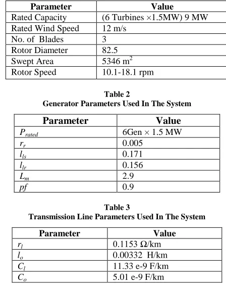
Table 1
Wind Turbine Parameters Used In The System
Parameter Value
Rated Capacity (6 Turbines ×1.5MW) 9 MW Rated Wind Speed 12 m/s
No. of Blades 3 Rotor Diameter 82.5 Swept Area 5346 m2 Rotor Speed 10.1-18.1 rpm
Table 2
Generator Parameters Used In The System
Parameter Value
Prated 6Gen × 1.5 MW
rr 0.005
lls 0.171
llr 0.156
Lm 2.9
pf 0.9
Table 3
Transmission Line Parameters Used In The System
Parameter Value
rl 0.1153 Ω/km
lo 0.00332 H/km
Cl 11.33 e-9 F/km
Co 5.01 e-9 F/km
[image:3.612.56.277.501.570.2]In this paper we have analyzed the same cases on a model implemented similar to Indian distribution and transmission system using Simulink (MATLAB) tool. Also the evaluation of STATCOM for providing dynamic reactive power compensation during grid faults in a DFIG-based STATCOM is analyzed. Table 4 shows the parameters of the STATCOM used.
Table 4 Statcom Parameters
Rating 3 MVA
Mode of operation Voltage regulation mode
Voltage at the point of
common coupling 11 kV
[image:3.612.326.563.540.635.2]International Journal of Emerging Technology and Advanced Engineering
Website: www.ijetae.com (ISSN 2250-2459,ISO 9001:2008 Certified Journal, Volume 6, Issue 3, March 2016)
130
A.Steady State Response of the System:
Wind speed with initial value of 8 m/s is applied which increases to a final value of 12 m/sec at t = 5 sec. as shown in Fig. 4.
[image:4.612.324.557.128.340.2]Ti me (s)
Fig. 4 Wind speed profile
The control mode of DFIG-based wind farm block is set to voltage regulation mode regulation mode with reference voltage of 1 pu on the base of generator rating which is 6*1.5 MVA and V = 440 V at bus B440. At t= 5 sec, the generated active power starts increasing with the increase
in wind speed and increases up to 7 MW as shown in Fig. 5.
Time (s)
Fig.5 DFIG generated active power
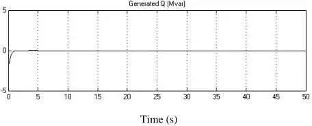
Fig. 6 shows the generated reactive power of DFIG at steady state, which is controlled to maintain the voltage at PCC (Bus B440) at 1 pu shown in Fig. 7. and also maintains the DC link capacitor voltage of DFIG constant at 1200 V as shown in Fig. 9.
[image:4.612.45.288.191.290.2]Time (s)
Fig.6 DFIG generated reactive power
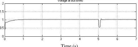
Fig. 7 and Fig. 8 show the voltage and current respectively at the point of common coupling (Bus B440)
Time (s)
Fig.7 Voltage at the point of common coupling (Bus B440)
[image:4.612.327.550.365.444.2]Ti me (s)
Fig.8 Current at the point of common coupling (Bus B440)
[image:4.612.53.284.391.469.2]Time (s)
Fig.9 DC link capacitor voltage
Fig. 10 shows the variation in turbine speed which increases from 0.8 pu to 1.21 pu.
[image:4.612.325.556.491.590.2]Time (s)
Fig.10 Turbine speed
B. System Performance during Single Line to Ground (SLG) Fault with STATCOM and RSC Blocking:
[image:4.612.52.280.557.649.2]International Journal of Emerging Technology and Advanced Engineering
Website: www.ijetae.com (ISSN 2250-2459,ISO 9001:2008 Certified Journal, Volume 6, Issue 3, March 2016)
131
A temporary single line to ground fault is applied at t = 5
sec to the bus B3 (11kv) in Fig.3 for duration 5 sec. The
DFIG will not be able to exchange reactive power with the power system as the RSC of DFIG-based wind farm is set to var regulation mode with reference reactive power command equal to zero. In this paper the protection system of the wind turbine will trip the wind turbine when the PCC voltage will fall to 50%.
Fig. 11 shows that the voltage at bus B440 drops to 0.54 pu when single line to ground fault is applied to bus B3 at t = 5 sec.
Time (s)
Fig.11 PCC (Bus B440) voltage during SLGF
The wind turbine system will not trip as it is designed to trip when the PCC voltage drops to 50% and continue to generate active power as shown in Fig. 12.The DFIG will not exchange any reactive power with the power system as shown in Fig. 13 because the RSC of DFIG is blocked to prevent overcurrent in the rotor circuit.
[image:5.612.328.558.181.263.2]Time (s)
Fig.12 Generated active power during SLGF
Time (s)
Fig.13 Generated reactive power during SLGF
After installing 3 MVA STATCOM at bus B3,the
voltage at PCC has improved to 0.68 pu as shown in Fig. 14.
The STATCOM provides the required reactive power to maintain the wind warm in service during and after the SLGF.
Time (s)
Fig.14 PCC (Bus B440) voltage during SLGF with STATCOM
Fig. 15 and Fig. 16 show the generated active and reactive power respectively during SLGF with STATCOM.
[image:5.612.57.278.269.344.2]Time (s)
Fig.15 Generated active power during SLGF with STATCOM
[image:5.612.333.560.320.381.2]Time (s)
Fig.16 Generated reactive power during SLGF with STATCOM
C. System Performance during Line to Line (L-L) Fault with STATCOM and RSC Blocking:
A temporary line to line fault is applied at t = 5 sec to the bus B3 (11kv) in Fig.3 for duration of 5 sec. The DFIG will not be able to exchange reactive power with the power system as the RSC of DFIG-based wind farm is set to Var regulation mode with reference reactive power command equal to zero.
[image:5.612.332.558.408.491.2] [image:5.612.54.283.452.528.2] [image:5.612.56.284.561.641.2]International Journal of Emerging Technology and Advanced Engineering
Website: www.ijetae.com (ISSN 2250-2459,ISO 9001:2008 Certified Journal, Volume 6, Issue 3, March 2016)
132
Time (s)
Fig.17 PCC (Bus B440) voltage during line to line fault
After installing 3 MVA STATCOM at bus B3,the voltage at PCC has improved to 0.67 pu as shown in Fig. 19. The STATCOM provides the required reactive power to maintain the wind warm in service during and after line to line fault.
Time (s)
Fig.18 PCC (Bus B440) voltage during line to line fault with STATCOM
One more important requirement necessary in the uninterrupted operation of the wind turbine is the stability of the dc- link voltage of variable frequency ac-dc-ac converter (VGC) in the rotor circuit. Fig. 19 and Fig. 20 show that there is drop in the overshoot of the dc-link voltage from 1252 V to 1245 V during L-L fault after STATCOM is installed. Decrease in the overshoot of the dc-link voltage means minimizing the risk of damage to the GSC and also helping RSC able to restart when the fault is cleared.
Time (s)
Fig.19 The overshoot of the DC link voltage during L-L fault without STATCOM
Time (s)
Fig.20 The overshoot of the DC link voltage during L-L fault with STATCOM
D. Voltage Sag of 30% at Bus 120 kV with STATCOM and RSC Blocking:
A temporary voltage sag of 30% is applied to the grid at bus 120kV in Fig.3.The voltage sag is applied at t = 5 sec and duration of 0.5 sec.fig.21 shows that the voltage at bus B440 dropped to 0.45 pu, due to which the wind turbine protection system will trip the wind farm.
Time (s)
Fig.21 PCC (Bus B440) voltage during a voltage sag of 30% at Bus 120kV
After installing 3 MVA STATCOM at bus B3,the voltage at PCC (bus B440) has improved to 0.6 pu as shown in Fig. 22. The STATCOM provides the required reactive power to maintain the wind warm in service during and after the grid disturbance.
Time (s)
International Journal of Emerging Technology and Advanced Engineering
Website: www.ijetae.com (ISSN 2250-2459,ISO 9001:2008 Certified Journal, Volume 6, Issue 3, March 2016)
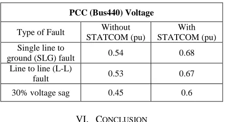
[image:7.612.54.286.166.291.2]133 Table 5
Comparison Of Pcc (Bus440) Voltage During Different Faults With And Without Statcom
PCC (Bus440) Voltage
Type of Fault Without STATCOM (pu)
With STATCOM (pu) Single line to
ground (SLG) fault 0.54 0.68 Line to line (L-L)
fault 0.53 0.67
30% voltage sag 0.45 0.6
VI. CONCLUSION
In this paper we have analyzed the role of STATCOM to maintain a DFIG based wind farm in service during grid faults which include single line to ground fault, line to line fault and voltage sag due to a remote fault. The SATCOM provided the required reactive power for the operation of the wind farm during and after the faults. The STATCOM was connected at the point of common coupling at bus B3 in the system. Simulink tool in MATLAB is used for the simulation of the system. The developed model in Simulink is similar to Indian distribution and transmission system.
The simulation results show that using faults the PCC voltage (bus B440) drops which may lead to overcurrent in the system. But after installing STATCOM, the PCC voltage has increased in all the three cases and voltages re-establish quickly after the fault is cleared. Without STATCOM the bus voltages cannot re-establish so quickly and cause the wind turbine to trip from the grid thus causing interrupted operation. Thus STATCOM increases the voltage stability, giving fast and smooth response.
REFERENCES
[1] „Indian Wind Energy association Report‟, accessiblefrom: http://www.inwea.org/installedcap acity.htm, accessed December 13, 2015.
[2] Tarek Medalel Masaud and P.K. Sen, ”Study of the Implementation of STATCOM on DFIG-Based Wind Farm Connected to a Power System,” Innovative Smart Grid Technologies (ISGT), IEEE PES, Washington, DC, USA, pp. 1-7, 2011.
[3] Mehrdad Fazli, Ali Reza Shafighi, Ali Fazli, Mehrdad Fazli, Ali Reza Shafighi and Ali Fazli, “Effects of STATCOM on Wind Turbines Equipped with DFIGs during Grid Faults,” IEEE Trans. 2010.
[4] M. J. Ghorbanian, F. Goodarzvand, A. Poudaryaei and W.N.L Mahadi, “Power quality improvement of grid connected doubly fed induction generator using STATCOM and BESS,” 4th International Conference on Engineering Technology and Techno preneuship (ICE2T) 2014, IEEE, Kuala Lumpur, pp. 110-115.
[5] Indrajit Koley, Swarnankur Ghosh, Avishek Ghose Roy, Dr.Pradip Kumar Saha and Dr.Gautam Kr. Panda5, “Matlab Modeling and Simulation of Grid Connected Wind Power Generation Using Doubly Fed Induction Generator,” International Journal of Computational Engineering Research (IJCER), vol. 04. no. 7, pp. 2250-3005, July-2014.
[6] Anil Gupta and Dr. Arun Shandilya, “Challenges of Integration of Wind Power on Power System Grid : A Review,” International Journal of Emerging Technology anddvanced Engineering , vol. 4, no. 4, April-2014.
[7] Brice Beltran, Mohamed Benbouzid and Tarek Ahmed-Ali,”Second-Order Sliding Mode Control of a Doubly Fed Induction Generator Driven Wind Turbine,” IEEE Tran. on energy conversion,vol. 27, no. 2, June- 2012.
[8] Alejandro Rolán , Joaquín Pedra , and Felipe Córcoles, “Detailed study of DFIG-based wind turbines to overcome the most severe grid faults,” Electrical power and Energy Systems, vol. 62, pp.868-872, June- 2014.
[9] J. Mohammadi, S. Afsharnia and S. Vaez-Zadeh (2014) „Efficient fault-ride-through control strategy of DFIG-based wind turbines during the grid faults,” Electrical power and Energy Systems, vol.78, pp.88-95, Nov.-2013.
[10] Abdullah AsuhaimiB.MohdZin,Mahmoud Pesaran H.A., Azhar B.Khairuddin, Leila Jahanshaloo and OmidShariati, “„An overview on doubly fed induction generators′ controls and contributions to wind based electricity generation,” Electrical power and Energy Systems, vol.27, pp.692-708, Aug.-2013.
[11] Li Wang and Dinh-Nhon Truong, “Stability Enhancement of DFIG-Based Offshore Wind Farm Fed to a Multi-Machine System Using a STATCOM.” IEEETrans. on power systems, vol. 28, no.3, Aug.-2013.
[12] Lab-Volt Ltd. (2011) „PRINCIPLES OF DOUBLY-FED INDUCTION GENERATORS (DFIG)‟, Courseware Sample, Canada.
[13] Large Scale Grid Integration of Renewable Energy Sources, Central Electricity Authority November 2013
[14] R. Mani Murali, P.J. Vidya, Poonam Modi and Seelam Jaya Kumar, “Site selection for offshore wind farms along the Indian coast,” International Journal of marine Sciences, vol. 43, no. 7,July-2014. [15] IIT Kanpur (1999) „AUTOMATION IN POWER DISTRIBUTION‟,
vol.2, no.2., Accessed on 20 Dec 2015, available at“http://www.iitk.ac.in/infocell/Archive/dirmar1/power_distribution .html”