International Journal of Emerging Technology and Advanced Engineering
Website: www.ijetae.com (ISSN 2250-2459, ISO 9001:2008 Certified Journal, Volume 5, Issue 7, July 2015)
497
Thermal Analysis for Performance Improvement of Air
Conditioner Using Material Modification
M. Anil Kumar
1, M. Nagaraju
2, J. Vamshidhar
31M.Tech, Turbomachinery Institute of Technology and Sciences, Medak, Telangana, India. 2 HOD, Mechanical, Turbomachinery Institute of Technology and Sciences, Medak, Telangana, India.
3Holy Mary Institute of Technology, Ranga Reddy, Telanagana, India.
Abstract—Air Conditioner (often referred to as AC) is a home appliance, system, or mechanism designed to dehumidify and extract heat from an area. In construction, a complete system of heating, ventilation and air conditioning is referred to as "HVAC". Air conditioning evaporator works by absorb heat from the area that need to be cooled. It does that by maintaining the evaporator coil at low temperature and pressure than the surrounding air. Since, the AC evaporator coil contains refrigerant that absorbs heat from the surrounding air, the refrigerant temperature must be lower than the air. The main aim of present work is to do thermal analysis on evaporator with selected fin material and refrigerant. Presently the material used for coils is copper and the material used for fins is copper or aluminium G Al Cu 4IMG 204 whose thermal conductivity is 110-150W/m k. For present work the copper plate, Al99 (1100) and Al 204 plate material is used for fin. To validate the temperatures and other thermal quantities like flux and gradient, thermal analysis is done on the evaporator coil by applying properties copper and present fin material. And also we are varying inside cooling fluid Hydrocarbon (HC) and Hydrochloroflouro carbon (HCFC). The best material and best fluid for the evaporator of our design can be checked by comparing the results. Thermal analysis is done in ANSYS. Finally result extracted from simulation is analyzed for its performance.
I. INTRODUCTION
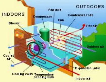
[image:1.612.339.549.242.404.2]An air conditioner (often referred to as AC) is a home appliance, system, or mechanism designed to dehumidify and extract heat from an area. The cooling is done using a simple refrigeration cycle. In construction, a complete system of heating, ventilation and air conditioning is referred to as "HVAC". Its purpose, in a building or an automobile, is to provide comfort during either hot or cold weather.
Fig 1: A typical home air conditioning unit
II. THEORY OF AIR CONDITIONING SYSTEM
1) Refrigeration cycle:
Refrigeration cycle
International Journal of Emerging Technology and Advanced Engineering
Website: www.ijetae.com (ISSN 2250-2459, ISO 9001:2008 Certified Journal, Volume 5, Issue 7, July 2015)
498 In the refrigeration cycle, a heat pump transfers heat from a lower-temperature heat source into a higher-temperature heat sink. Heat would naturally flow in the opposite direction. This is the most common type of air conditioning. A refrigerator works in much the same way, as it pumps the heat out of the interior and into the room in which it stands.
This cycle takes advantage of the way phase changes work, where latent heat is released at a constant temperature during a liquid/gas phase change, and where varying the pressure of a pure substance also varies its condensation/boiling point.
The most common refrigeration cycle uses an electric motor to drive a compressor. In an automobile, the compressor is driven by a belt over a pulley, the belt being driven by the engine's crankshaft (similar to the driving of the pulleys for the alternator, power steering, etc.). Whether in a car or building, both use electric fan motors for air circulation. Since evaporation occurs when heat is absorbed, and condensation occurs when heat is released, air conditioners use a compressor to cause pressure changes between two compartments, and actively condense and pump a refrigerant around. A refrigerant is pumped into the evaporator coil, located in the compartment to be cooled, where the low pressure causes the refrigerant to evaporate into a vapor, taking heat with it. At the opposite side of the cycle is the condenser, which is located outside of the cooled compartment, where the refrigerant vapor is compressed and forced through another heat exchange coil, condensing the refrigerant into a liquid, thus rejecting the heat previously absorbed from the cooled space.
By placing the condenser (where the heat is rejected) inside a compartment, and the evaporator (which absorbs heat) in the ambient environment (such as outside), or merely running a normal air conditioner's refrigerant in the opposite direction, the overall effect is the opposite, and the compartment is heated. This is usually called a heat pump, and is capable of heating a home to comfortable temperatures (25 °C; 70 °F), even when the outside air is below the freezing point of water (0 °C; 32 °F).
III. THERMAL ANALYSIS OF EVAPORATOR BY USING
HYDROCARBON FLUID
A. Thermal Analysis of Evaporator using Copper for Tube and Plate :
Input Parameters:
Tube Material - Copper
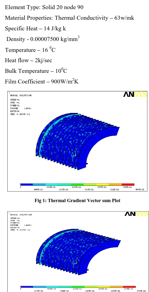
Element Type: Solid 20 node 90
Material Properties: Thermal Conductivity – 63 w/mk
Specific Heat – 14 j/kg k
Density - 0.00007500 kg/mm3
Plate Material - Copper
Element Type: Solid 20 node 90
Material Properties: Thermal Conductivity – 63w/mk
Specific Heat – 14 J/kg k
Density - 0.00007500 kg/mm3
Temperature – 16 0C
Heat flow – 2kj/sec
Bulk Temperature – 100C
[image:2.612.316.562.198.679.2]Film Coefficient – 900W/m2K
Fig 1: Thermal Gradient Vector sum Plot
International Journal of Emerging Technology and Advanced Engineering
Website: www.ijetae.com (ISSN 2250-2459, ISO 9001:2008 Certified Journal, Volume 5, Issue 7, July 2015)
499
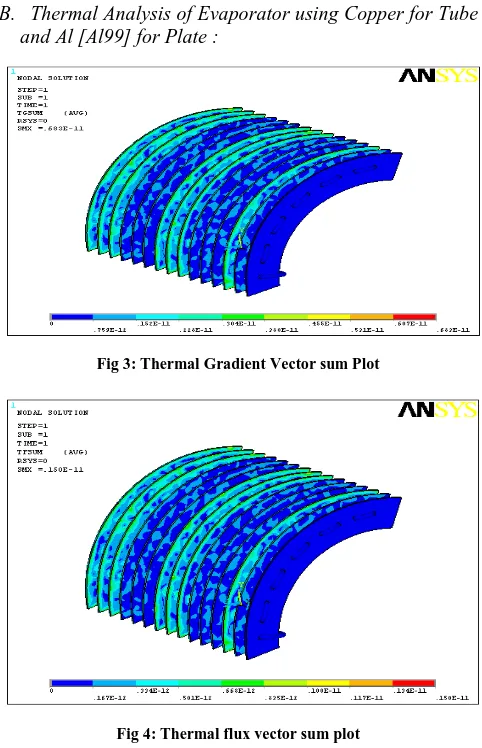
[image:3.612.257.558.105.662.2]B. Thermal Analysis of Evaporator using Copper for Tube and Al [Al99] for Plate :
Fig 3: Thermal Gradient Vector sum Plot
Fig 4: Thermal flux vector sum plot
C. Thermal Analysis of Evaporator using Copper for Tube and Al 204 for Plate:
[image:3.612.326.556.123.271.2]Fig 5: Thermal Gradient Vector sum Plot
Fig 6: Thermal flux vector sum plot
IV. THERMAL ANALYSIS OF EVAPORATOR BY USING
HYDROFLOUROCARBON FLUID
[image:3.612.49.290.133.507.2]A. Thermal Analysis of Evaporator using Copper for Tube and Plate :
Fig 7: Thermal Gradient Vector sum Plot
[image:3.612.323.573.329.634.2]International Journal of Emerging Technology and Advanced Engineering
Website: www.ijetae.com (ISSN 2250-2459, ISO 9001:2008 Certified Journal, Volume 5, Issue 7, July 2015)
500
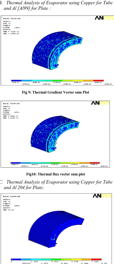
[image:4.612.320.566.126.567.2]B. Thermal Analysis of Evaporator using Copper for Tube and Al [Al99] for Plate :
Fig 9: Thermal Gradient Vector sum Plot
Fig10: Thermal flux vector sum plot
C. Thermal Analysis of Evaporator using Copper for Tube and Al 204 for Plate:
Fig 11: Thermal Gradient Vector sum Plot
Fig 12: Thermal flux vector sum plot
V. RESULTS
TABLE I
Thermal analysis for fluid Hydrocarbon
Combination
Nodal temperature (0C)
Thermal Gradient (K/mm)
Thermal Flux (W/mm2)
Copper Tube
Copper Plate 16 0.4e
-11 0.252e-11
Copper Tube
Al 99 Plate 16 0.683e
-11
0.15e-11
Copper Tube
[image:4.612.51.291.134.687.2]International Journal of Emerging Technology and Advanced Engineering
Website: www.ijetae.com (ISSN 2250-2459, ISO 9001:2008 Certified Journal, Volume 5, Issue 7, July 2015)
[image:5.612.47.294.134.374.2]501
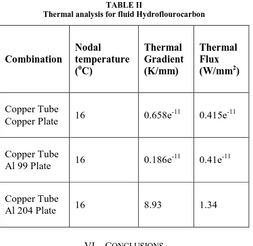
TABLE II
Thermal analysis for fluid Hydroflourocarbon
Combination
Nodal temperature (0C)
Thermal Gradient (K/mm)
Thermal Flux (W/mm2)
Copper Tube
Copper Plate 16 0.658e
-11 0.415e-11
Copper Tube
Al 99 Plate 16 0.186e
-11 0.41e-11
Copper Tube
Al 204 Plate 16 8.93 1.34
VI. CONCLUSIONS
In the present research work the 3D modeling for an air-cooled evaporator for 1.5 ton air conditioner is done using Pro/Engineer.
The thermal analysis is performed on the evaporator by taking tube material as copper and varying the plate materials, Copper, Al99, Al204. The analysis is also done
by varying refrigerant Hydrocarbon and Hydro
fluorocarbon.
In thermal analysis, the thermal properties like nodal temperature, thermal gradient and thermal flux are found out.
The result shows that the thermal gradient as well as thermal flux is more with the combination of Copper tube and Al 204 plate.
When comparing Hydrocarbon and Hydro fluorocarbon, using Hydro fluorocarbon is more advantageous since its thermal gradient is more with all combinations.
The nodal temperature is constant in all the combinations with Hydrocarbon and Hydro fluorocarbon fluids.
REFERENCES
[1] Wang, C. C., Lee, C. J., Chang, C. T., and Chang Y. J., 1999. “Some Aspects of Plate Finand Tube Heat Exchangers with and without Louvers,” J. Enhanced Heat Transfer, vol. 6, no. 5, pp. 357-368.
[2] Wang, C. C., Chi, Y. P. Chang, K. Y. C., and ChangY. J., 1998. “An
Experimental Study of Heat Transfer and Friction Characteristics of Typical Louver Fin and Tube Heat Exchangers,” Int. J. of Heat and Mass Transfer, vol. 41, no. 4-5, pp.817-822.
[3] Chi, K., Wang, C. C., Chang, Y. J., and Chang, Y. P., 1998. “A Comparison Study of Compact Plate Fin and Tube Heat Exchangers,” ASHRAE Transactions, vol. 104, no. 2, pp. 548-555.
[4] Rich, D. G., 1973. “The Effect of Fin Spacing on the Heat Transfer