Mobile Robot Navigation using Wavelet Network and
Fuzzy Logic
Mustafa I. Hamzah Turki Y. Abdalla
Department of Electrical Engineering Department of Computer Engineering University of Basrah , Basrah,Iraq University of Basrah, Basrah,Iraq
ABSTRACT
This paper present the proposed autonomous mobile robot navigation scheme. The navigation of mobile robot in unknown environment with obstacle avoidance is based on using fuzzy logic and wavelet network. Several cases are designed and modeled in Simulink and MATLAB. Simulation results show good performance for the proposed scheme.
General Terms
Mobile robot motion and planning Control.
Keywords
An autonomous mobile robot ,Wavelet Neural network ,Particle swarm optimization ,Navigation ,Path Planning, Obstacle avoidance.
1.
INTRODUCTION
An autonomous mobile robots have been used in many applications due to the high level of performance and reliability such as moving material in unknown environment such as warehouses, offices and industries .The robot has the ability to plan motion and to navigate autonomously avoiding any type of obstacles in different environments. This is a reactive strategy which is completely based on sensory information [1].The common used sensing devices for obstacle avoiding are infrared sensor ,ultrasonic sensor ,laser range finder .The cause of choosing IR sensors is that ,IR sensor are simple, and has the fast response time[2]. In order to achieve autonomous navigation, the mobile robot must be capable of sensing the environment, planning a route from an initial to a goal position with obstacle avoidance, and controlling the mobile robot turning angle and linear velocity to reach the target . An autonomous robot can avoid obstacles on the path and smoothly move to the target [3].
The purpose of this paper is to design an autonomous mobile robot which can interact and plan its motion in unknown environment depending on capture information from nine IR detection sensors. Obstacle avoidance and goal reaching algorithm is proposed using Fuzzy logic .The Obstacle avoidance and goal reaching controllersare connected to a wavelet network based motion controller through mobile robot kinematic model to get complete autonomous mobile robot system .
2.
NAVIGATION OF MOBILE ROBOT
The navigation of a mobile robot can be considered as a task of determining a collision free path that enables the mobile robot to travel through an obstacle course from an initial configuration to a goal configuration [4].In unknown environment we need at least the following types of reactive navigation behaviors (i) Move behavior (ii) Obstacle avoidance behavior. (iii) Wall following behavior.
Move behavior is to make the robot move in free
avoidance is used. Wall following is a typical example of a mission where reactive navigation is required. The motion control of mobile robots among obstacles is classified to three possible motion tasks as follows:
Point-to-point motion (goal searching):
The robot is assigned to reach a desired goal configuration starting from a given initial configuration, while avoiding collision with obstacles. This task is sometimes called Path planning .
Path following:
The robot must reach and follow a geometric path in the Cartesian space starting from a given initial configuration (on or off the path).
Trajectory tracking:
The robot must reach and follow a trajectory in the Cartesian space (i.e., a geometric path with an associated timing law) starting from a given initial configuration.
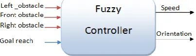
A reactive navigation system based fuzzy control, as shown in Figure(1), is proposed for our robot. The inputs are the data (signals) provided by sensors in front , left and right obstacle‘s range and the reach of the goal. The outputs are crisp values (commands)of the speed and the orientation of the robot as it reacts with the changing of the environment[5].
The components of FLC are an inference engine and a set of linguistic IF–THEN rules that encode the behavior of the mobile robot, However, the main difficulty in designing a fuzzy logic controller is the efficient formulation of the fuzzy IF–THEN rules[6]. Figure (2) Shows that Fuzzy controller is made up of 3 steps: 1) Fuzzification: converts controller inputs into information that the inference mechanism can be used to activate and apply rules. 2) Rule - Base: (a set of If-Then rules). 3) Defuzzification: This converts the conclusions of the interface mechanism into actual inputs for the process.
[image:1.595.324.526.463.521.2] [image:1.595.323.523.681.759.2]
3.
THE CONTROL SYSTEM OF A
MOBILE ROBOT
The control system of a mobile robot can be viewed as a hierarchical system of three controllers: the motion planner, the motion controller, and the actuator driver. This structure is illustrated in Figure(3). At the highest level is the motion planner. At this level, what path and what velocity profile the robot is to follow are determined [7].
The controller at the next level takes the information of the speed and position as a reference(Desired input). At this level, the actual position and velocity of the robot are measured and compared to the desired position and velocity (as determined by the motion planner). Based on the errors between the actual and desired states, the controller determines what motor signals are necessary to achieve the desired position and velocity. At the lowest level are the actuator drivers. These controllers motor signals commands from the previous level controller and determine what actual velocity and steering angle to the motors are necessary to achieve the desired position or rotational speed[8].
4.
WAVELET NEURAL NETWORK
The wavelet neural network is shown in Figure(4). It represents the model of multi-input and multi-output (MIMO) WNN with three layers. The node number of the input layer is M, the hidden layer is K and the output layer is N. The impulse function of hidden layer is wavelet basis function. The impulse function of output layer is sigmoid function. The formula for the computation is as follows[9].
Figure(4): The structure diagram of WNN
The wavelet network operation consists of two phases. in the first phase , the network architecture is determined for certain application. In the second phase the parameter of the network are updated so that the approximation errors are minimized .
4.1
A wavelet neural network based on
PSO
The wavelet neural networks with PSO is shown in Figure(5). The elements of the location vector in the Particle Swarms is defined as the link weightsbetween each layer of the wavelet neural networks and telescopic translation parameter and . Fitness function is the Mean square error function E( ) of the wavelet neural networks. As seen in the Equation(4).
where y(i) is the model output, and D(i) is the desired output. represents the total training patterns.
4.2
WNN-PSO training algorithm process
1. Set the initial value of telescopic factor and thetranslation factor of the wavelet networks parameters .
2. Initiate the parameters of the Particle Swarms: Set the particle number m; fitness threshold ε ; set the maximum allowable number of iterative step MaxIter; set the accelerating factor , ; set the minimum min ω and maximum max of ω ; the particle location ; speed
initial to the random number between 0 and 1.
3. Iterative update the location x and the speed of every particle according to the formula of the Particle Swarm Optimization (5) ,(6) and (7),
Fig(3): The Control Hierarchy of a mobile robot
and e(i)=
Swarm Optimization (5) ,(6) and (7) ,
record the history optimal location vector of every particle
and overall optimal location vector . Calculate the fitness
value according to Equation (4), record the fitness value Fitness and Fitness corresponding to and .
4. Test if the fitness value reach to the setting value, and if the iterations number reach to the highest. If the Fitness
≤ setting value or the iterations number reach to the
highest, the iterations over, or go to step (3).
Figure(5) shows the process of training Wavelet network parameters and Select optimal PIDs values using PSO algorithm and Figure(6) shows the optimization based on the Particle Swarm Optimization. PID controllers are used to improve response and reduce learning cycle[11].
Fig(5) :Mobile Robot Control system diagram using PSO-
Fig(6): PSO based WNN Training Algorithm
Path planning
When the mobile robot is traveling toward its final target in unknown environment with different shapes of obstacles in different locations .Two types of planning tasks are proposed, one for goal reaching and the other is for obstacle avoidance Each task is performed by one fuzzy controller .The obstacle sense output signal is used to activate one of these tasks as shown in Figure(7).
Fig(7): Obstacle avoidance and goal reach fuzzy
5.
GOAL REACHING
When the mobile robot is traveling toward its final target in unknown environment with no obstacles detected by IR sensors .The Goal Reaching task is expected to align the robot’s heading with the direction of the goal ,goal angle is the orientation difference between the robot axel and the goal. The robot heading angle θ can be determined by encoder. The fuzzy controller has one input . It is used to implement
the navigation between two points, initial point and goal point. This controller has only one input ( diff) the difference between the Azimuth (the mobile robot heading angle), and the goal angle ( g) as shown in Figure (8). The outputs of this controller are right wheel and left wheel angular speeds. Figure (9)shows fuzzy inference system for goal reaching controller.
Fig(8) goal orientation signals description
Fig(9):Fuzzy inference system for goal reaching Fuzzy
Fig(13): Sensors location on mobile robot
The input variable has 5 fuzzy sets : Zero (Z), Small Positive (SP), Big Positive (BP), Small Negative (SN), and Big Negative (BN) as shown in Figure(10) .
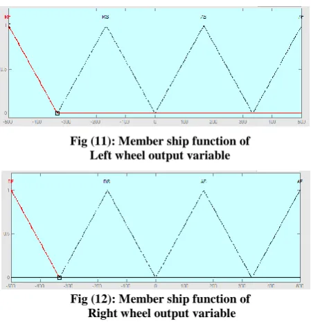
Each output variable has four fuzzy sets : Return Slow (RS), Return Fast (RF), Ahead Slow (AS), and Ahead Fast (AF) as shown in Figure (11) and figure(12). The controller rule base is given in Table (1).
Fig (11): Member ship function of Left wheel output variable
Fig (12): Member ship function of Right wheel output variable
Table (1): Fuzzy rules for goal reach fuzzy controller
5.1 Mobile Robot environment and sensors
arrangement
The mobile robot has two encoders fixed on axels of left and right wheel used to determine the current position of mobile robot. The mobile robot use nine infrared sensors (four in the left, four in the right and one in front) to detect the surrounding obstacles and find the distance from robot and obstacle and find the angle of obstacle and mobile robot .The IR sensors are mounted as:
are mounted in the left of the robot.
are mounted in the front of the
robot.
are mounted in the right of the
robot.
The active range of distance between obstacle and mobile robot can be determined for each IR sensor is assumed to be between 0~1m .The distance for nine sensors are denoted by A simulation method by use of
Matlab and an experiment in unknown environments will be given .Assume the distance to front, left and right obstacles are:
5.2 Obstacle avoidance
When the mobile robot is traveling toward its final target in unknown environment , it faces different shapes of obstacles in different location . Obstacles are detected by nine IR sensors which send information of distance between obstacle and mobile robot to a fuzzy logic controller. Fuzzy logic control (FLC) is adopted to control the movements of the right and left wheels. The two outputs are the motor commands to both the left an right motors.In this way, the mobile robot can avoid obstacles autonomously.
Fig(14): Fuzzy inference system for Obstacle avoidance
Input Output
diff WR
W
Z AF
AF
SP AS
RS
BP AF
RF
SN RS
AS
BN RF
AF
[image:4.595.51.269.123.224.2] [image:4.595.51.276.304.537.2] [image:4.595.348.546.341.512.2] [image:4.595.54.275.580.761.2] [image:4.595.325.537.667.728.2]The control structure given in Figure(14) is based on a task for avoiding obstacles, the inputs of the control system are sensors data and the outputs are the motor commands. The fuzzy logic system has 3 inputs and 2 outputs. The three inputs are the distances between the robot and the obstacle from 9 infrared sensors and are expressed respectively as S_L, S_F and S_R. S_F is the data from the middle sensor, and S_L is the data from the four sensors on the left side, and S_R is
just like S_L.
Fuzzy Sets
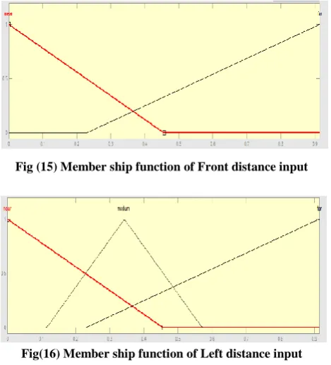
For S_F input, 2 membership functions (far and near) have been defined, and for S_L or S_R, 3 membership functions (far, medium and near), and for every output 7 membership functions (Reverse Fast ( Fast), Reverse Medium (-Med), Reverse Slow (-Slow), Stop and Forward Fast (Fast), Forward Medium (Med), Forward Slow (Slow)). S_F can be set up on four level distances respectively. S_L and S_R can be set upon five level distances. The graphical representation of membership functions for S_L and S_R are given by Figures(15),(16),(17) .
Fig (15) Member ship function of Front distance input
Fig(16) Member ship function of Left distance input
Fig(17) Member ship function of Right distance input
The graphical representation of membership functions for outputs are given by Figure(18) and
Fig (18): Membership function of Right wheel output variable
Fig (19): Member ship function of Right wheel output variable
Fuzzy Inference Process
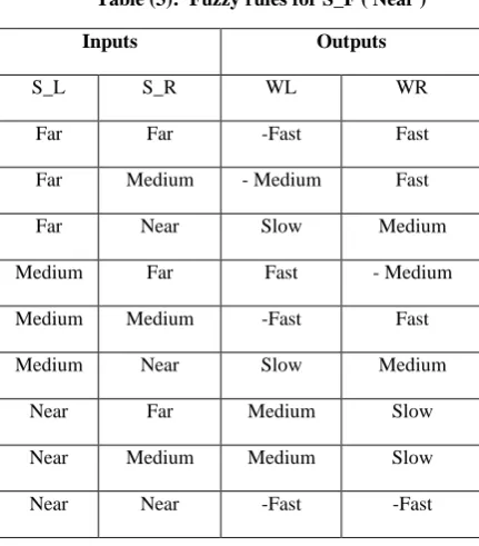
The fuzzy control rules are given in Table(2) and Table(3).
Table (2): Fuzzy rules for S_F ( Far )
Inputs Outputs
S_L S_R WL WR
Far Far Fast Fast
Far Medium Medium Fast
Far Near Slow Fast
Medium Far Fast Medium
Medium Medium Medium Medium
Medium Near - Slow Fast
Near Far Fast Slow
Near Medium Fast - Slow
[image:5.595.320.543.125.224.2] [image:5.595.322.539.271.375.2] [image:5.595.52.287.351.610.2] [image:5.595.317.539.461.694.2] [image:5.595.316.540.463.695.2]Table (3): Fuzzy rules for S_F ( Near )
6.
RESULTS
Matlab\simulink environment computes the location of the goal and obstacles, simulate the sensory data, finds the distance from the obstacles and feed this information to the fuzzy controller that make the movement decision (speed and orientation) and used for testing the ability of autonomous mobile robot for goal reaching with static obstacle avoidance in the way toward the goal . Two fuzzy logic controllers are used for path planning to navigate among static obstacles, one controller is used for goal reaching and another for obstacle avoidance depending on sensing information from unknown environment .The navigation from start point to end(target)point. The mobile robot stops when it arrives the goal point within 0.03 m accuracy of distance between the center of the mobile robot( , ) and the target point ( , ) .Figure (20) shows the navigation of mobile robot from starting point(0,0) toward target point(12,16) and the mobile robot can move among the obstacles without hit .
Fig (20): Autonomous mobile robot navigation
In the Figure (21)another goal point is selected and also the mobile robot can move among the obstacles without hit from start point(0,0) to goal point(0,16).
Fig (21): Autonomous mobile robot navigation
7.
CONCLUSION
In this paper ,an efficient autonomous mobile robot navigation scheme using fuzzy logic and wavelet network is designed and implemented. The method is tested in unkown environment and gives good performance for navigation toward the goal without hitting any obstacle.
8.
REFERENCES
[1] C. Lanzoni and A. Sanchez," Sensor-based motion planning for car-like mobile robots in unknown environments," IEEE International Conference on Robotics & Automation Taipei,pp.4258- 4263, Taipei, Taiwan, 2003 .
[2] I. Gavrilut, V. Tiponut and A. Gacsadi ,"Mobile Robot Navigation based on CNN Images Processing –An Experimental Setup," Wseas Transactions on systems, ISSN: 1109-2777, ,Vol. 8, No. 8, pp. 947-956,2009.
[3] O.Hachour ," Path planning of Autonomous Mobile robot," International journal of systems application engineering & development, Vol.04, No.02 ,pp.178-190, 2008.
[4] C. G. Rusu and I. T. Birou , "Obstacle Avoidance Fuzzy System for Mobile Robot with IR Sensors," 10th International Conference on development and application systems, Romania ,2010.
[5] ImenAyari, AbderrazakChatti,"Reactive Control Using Behavior Modelling of a Mobile Robot" ,International Journal of Computers, Communications & Control Vol. 02 , No.03, pp. 217-228,2007.
[6] Wahyudi and J. Jalani," Design and Implementation of Fuzzy Logic Controller for Intelligent Gantry Crane System", International Conference on Mechatronics, Vol. 02 , No.05, pp. 21-30 , Malaysia,2005.
[7]PornpormBoonporm,"Online path replanning of autonomous mobile robot with Spline based algorithm",
Inputs Outputs
S_L S_R WL WR
Far Far -Fast Fast
Far Medium - Medium Fast
Far Near Slow Medium
Medium Far Fast - Medium
Medium Medium -Fast Fast
Medium Near Slow Medium
Near Far Medium Slow
Near Medium Medium Slow
[image:6.595.49.265.78.324.2] [image:6.595.320.545.106.332.2] [image:6.595.47.281.567.723.2]2012 International Conference on System Modeling and Optimization , Singapore,2012
[8] Lon-Chen Hung and Hung-Yuan Chung ,"Design of Hierarchical Fuzzy Logic Control for Mobile Robot System,"IEEE Intelligent Control and Automation, Vol.06, NO.43 , 2006.
[9] K. Prasanta," Short-Term Load Forecasting using PSO Based Local Linear Wavelet Neural Network", International Journal of Instrumentation, Control and Automation (IJICA) ,Vol.1, No.02, 2011.
[10]H. Yunlong and Y. Shiming, "Explosive Ordnance Disposal Robot Path Planning Based on Danger Model Immune Wavelet NeuralNetwork",Advances in information Sciences and Service Sciences, Vol.03, No.11, , 2011.
[11]P. Kumar," Short-Term Load Forecasting using PSO Based Local Linear Wavelet Neural Network",International Journal of Instrumentation, Control and Automation,Vol.01, No.02, , 2011.