© 2016, IRJET | Impact Factor value: 4.45 | ISO 9001:2008 Certified Journal
| Page 1549
FAULT SECURE ENCODER AND DECODER FOR NANO-MEMORY
APPLICATIONS
P.Kanvitha,N.Naga Raju
PG
Student(VLSI and EMBEDDED SYSTEMS),Electronics and Communication Engineering,Chalapathi
Institute of Engineering and Technology,Guntur,Andhra Pradesh,India.
Assistant professor, Electronics and Communication Engineering,Chalapathi Institute of Engineering and
Technology,Guntur,Andhra Pradesh,India.
---***---Abstract
- Memory cells have been protected from soft
errors for more than a decade; due to the increase in soft error rate in logic circuits, the encoder and decoder circuitry around the memory blocks have become susceptible to soft errors as well and must also be protected. We introduce a new approach to design fault-se-cure encoder and decoder circuitry for memory designs. The key novel contribution of this paper is identifying and defining a new class of error-correcting codes whose redundancy makes the de-sign of fault-secure detectors (FSD) particularly simple. We fur-ther quantify the importance of protecting encoder and decoder circuitry against transient errors, illustrating a scenario where the system failure rate (FIT) is dominated by the failure rate of the en-coder and decoder. We prove that Euclidean Geometry Low-Den-sity Parity-Check (EG-LDPC) codes have the fault-secure detector capability. Using some of the smaller EG-LDPC codes, we can tol-erate bit or nanowire defect rates of 10% and fault rates of upsets/device/cycle, achieving a FIT rate at or below one for the entire memory system and a memory density of bit/cm with nanowire pitch of 10 nm for memory blocks of 10 Mb or larger. Larger EG-LDPC codes can achieve even higher reliability and lower area overhead.
Key Words: Decoder, encoder, fault tolerant, memory,
nan-otechnology.
1.INTRODUCTION
Memory cells have been protected from soft errors for more than a decade; due to the increase in soft error rate in logic circuits, the encoder and decoder circuitry around the memory blocks have become susceptible to soft errors as well and must also be protected. We introduce a new approach to design fault-secure encoder and decoder circuitry for memory designs.[1,2]
Nanotechnology provides smaller, faster, and lower energy devices, which allow more powerful and compact circuitry; however, these benefits come with a cost, the nano scale devices may be less reliable. Thermal- and shot-noise estimations alone suggest that the transient fault rate of an individual nano scale device (e.g., transistor or nano wire) may be orders of magnitude higher than today‟s devices. As a result, we can expect combinational logic to be susceptible to transient faults, not just the storage and communication systems.[3,4]
Therefore, to build fault-tolerant nano scale systems, we must
protect both combinational logic and memory against transient faults. In the present work we introduce a fault-tolerant nano scale memory architecture which tolerates transient faults both in the storage unit and in the supporting logic (i.e., encoder and decoder (corrector) circuitry.
1.1
Statement of problem
Traditionally, memory cells were the only circuitry susceptible to transient faults, and all the supporting circuitries around the memory i.e., encoders and decoders were assumed to be free. As a result most of prior work designs for fault-tolerant memory systems focused on protecting only the memory cells. However, as we continue scaling down feature sizes or use sub lithographic devices, the surrounding circuitries of the memory system will also be susceptible to permanent defects and transient faults.
One approach to avoid the reliability problem in the surrounding circuitries is to implement these units with more reliable devices (e.g., more reliable CMOS technologies). However, from an area, performance, and power consumption point of view it is beneficial to implement encoders and decoders with scaled feature size or nanotechnology devices.
Almost all of the proposed fault tolerant encoders and decoders so far, use the conventional fault tolerant scheme (e.g., logic replication or concurrent parity prediction) to protect encoder and corrector circuitry. That is, they add additional logic to check the correctness of the circuit calculation.
1.2
Objectives of the work
A new approach is introduced to design fault-secure encoder and decoder circuitry for memory designs. The key novel contribution of this proposed system is identifying and defining a new class of Error-Correcting Codes (ECC) whose redundancy makes the design of Fault-Secure Detectors (FSD) particularly simple. This project present a fault-tolerant nano scale memory architecture which tolerates transient faults both in the storage unit and in the supporting logic (i.e., encoder and decoder (corrector) circuitry).
© 2016, IRJET | Impact Factor value: 4.45 | ISO 9001:2008 Certified Journal
| Page 1550
a) Any single error in the encoder or corrector circuitry can
only corrupt a single codeword digit
(i.e., cannot propagate to multiple codeword digits). b) There is a FSD circuit which can detect any limited
combination of errors in the received codeword or the detector circuit itself.
Property (a) is guaranteed by not sharing logic between the circuitry which produces each bit. The Property (b) FSD is possible with a more constrained definition for the Error Correcting Codes (ECC).
An error-correcting code (ECC) or Forward Error Correction (FEC) code is a system of adding redundant data, or parity data, to a message, such that it can be recovered by a receiver even when a number of errors (up to the capability of the code being used) were introduced, either during the process of transmission, or on storage. Since the receiver does not have to ask the sender for retransmission of the data, a back-channel is not required in Forward Error Correction (FEC), and it is therefore suitable for simplex communication such as broadcasting. Error-Correcting Codes (ECC‟s) are frequently used in lower-layer communication, as well as for reliable storage in media such as CDs, DVDs and hard disks.
Error-Correcting Codes (ECC‟s) are usually distinguished between convolution codes and block codes. Convolution codes are processed on a bit-by-bit basis. They are particularly suitable for implementation in hardware. Block codes are processed on a block-by-block basis. Examples of block codes are repetition codes, Hamming codes and multidimensional parity- check codes. Turbo codes and Low-Density Parity-Check Codes (LDPCC) are relatively new constructions that can provide almost optimal efficiency.
1.3 Methodology
In this proposed system, we introduce a fault-tolerant nano scale memory architecture which tolerates transient faults both in the storage unit and in the supporting logic (i.e., encoder, decoder (corrector), and detector circuitries).Particularly; we identify a class of Error-Correcting Codes (ECC‟s) that guarantees the existence of a simple fault-tolerant detector design. This class satisfies a new restricted definition for ECC‟s which guarantees that the ECC codeword has an appropriate redundancy structure such that it can detect multiple errors occurring in both the stored codeword in memory and the surrounding circuitries.
We call this type of Error-Correcting Codes, Fault-Secure Detector capable ECCs (FSD-ECC). The Parity-check Matrix of an FSD-ECC has a particular structure that the decoder circuit, generated from the parity-check Matrix, is Fault-Secure. We use the secure detection unit to design a fault-tolerant encoder and corrector by monitoring their outputs. If a detector detects an error in either of these units, that unit must repeat the operation to generate the correct output vector. Using
this retry technique, we can correct potential transient errors in the encoder and corrector outputs and provide a fully fault-tolerant memory system.
The novel contributions of this proposed system include the following:
a. A mathematical definition of ECC‟s which have
simple FSD which do not requiring the addition of further redundancies in order to achieve the fault-secure property
b. Identification and proof that an existing LDPC code
(EG-LDPC) has the FSD property.
2.
CODING SCHEMES
The technique introduced in this work exploits the existing structure of the ECC to guarantee the fault-secure property of the detector unit without adding redundant computations. We start with ECC definition for our fault-secure detector capable codes. Before starting the details of our new definition we briefly review basic linear ECCs.
2.1. Linear Block Error Correcting Codes
This section provides a brief introduction on linear block
ECC‟s. Let I = (i0, i1, ..., i k−1) be k-bit information vector that
will be encoded into n -bit codeword, C= (c0, c 1, ..., c n−1). For
linear codes the encoding operation essentially performs the following vector-matrix Multiplication.
C = I × G
Where, G is a k × n generator matrix.
A code is a systematic code if any codeword consists of the original k-bit information vector followed by (n – k) parity-bits. With this definition, the generator matrix of a systematic code must have the following structure.
G = [I: X] Where, I is a k × k identity matrix and
X is a k×(n−k) matrix that generates the parity-bits
The advantage of using systematic codes is that there is no need for a decoder circuitry to extract the information bits. The information bits are simply available in the first k bits of any encoded vector.[5]
A code is said to be cyclic code if for any codeword c, all the cyclic shifts of C is still a valid codeword. A code is cyclic if the rows of its parity-check matrix and generator matrix are the cyclic shifts of their first rows.
The checking or detecting operation is the following vector-matrix
© 2016, IRJET | Impact Factor value: 4.45 | ISO 9001:2008 Certified Journal
| Page 1551
Where, H is an (n−k)×n Parity-Check matrix.The (n − k)-bit vector S is called syndrome vector. A syndrome vector is zero if C is a valid codeword and non-zero if C is an erroneous codeword.
2.2. Creating a parity check matrix
The parity check matrix for a given code can be derived from its generator matrix and (vice-versa). If
the generator matrix for an [n,k]-code is in standard
form[6,7]
then the parity check matrix is given by
Where „I‟ is a (n-k) identity matrix.
„P‟ is a k x (n-k) matrix that generates parity bits.
Because, GHT=P-P=0
For any valid codeword x, Hx = 0. For any invalid codeword, the
syndrome vector S satisfies. The rows of a parity check matrix
are parity checks on the code words of a code. That is, they show how linear combinations of certain digits of each codeword equal zero.
2.3. ECC with Fault Secure Detector
In this proposed system the encoder is protected with parity-prediction and parity checker. The decoder is protected by adding a code checker (detector) block. If the code checker detects a non-codeword, then the error in the decoder is detected. Here we propose a multiple-error fault tolerant decoder and encoder that is general enough for any decoder and encoder implementation and for any kind of ECC that satisfies the restricted ECC definition. The restricted ECC definition which guarantees a fault-secure detector capable ECC is as follows:
Let C be an ECC with minimum distance d. C is FSD-ECC if it can detect any combination of overall (d – 1) or fewer errors in the received codeword and in the detector circuitry.
2.4. Euclidean Geometry LDPC Codes
Low-Density Parity -Check (LDPC) codes [5] are a class of recently re-discovered highly efficient linear block codes. They can provide performance very close to the channel capacity (the theoretical maximum) using an iterated soft-decision decoding approach, at linear time complexity in terms of their block length. LDPC codes were first introduced by Robert G. Gallager in his PhD thesis in 1960.LDPC codes are now used in many recent high-speed communication standards, such as DVB-S2 (Digital video broadcasting), WiMAX (IEEE 802.16e standard for microwave communications), High-Speed Wireless LAN (IEEE 802.11n), 10GBase-T Ethernet (802.3an) and
G.hn/G.9960 (ITU-T Standard for networking over power lines, phone lines and coaxial cable).
A Low Density Parity Check Code (LDPC) is one where the parity check matrix is binary and sparse, where most of the entries are zero and only a small fraction are 1's. In its simplest form the parity check matrix is constructed at random subject to some rather weak constraints on H.
2.5. Regular and Irregular LDPC Codes
A LDPC code is called regular if we is constant for every
columnregular and wr = wc · (n/m) is also constant for every
row. If H is low density but the numbers of 1‟s in each row or column aren‟t constant the code is called a irregular LDPC code irregular.[8]
This section reviews the construction of Euclidean Geometry codes based on the lines and points of the corresponding finite geometries. Euclidean Geometry codes are also called EG-LDPC codes based on the fact that they are low-density parity-check (LDPC) codes. LDPC codes have a limited number of 1‟s in each row and column of the matrix. This limit guarantees limited complexity in their associated detectors and correctors making them fast and light weight.
Let EG be a Euclidean Geometry with n points and j lines.EG is a finite geometry that is shown to have the following fundamental structural properties:
1)Every line consists of p points.
2)Any two points are connected by exactly one line.
3)Every point is intersected by y lines.
4)Two lines intersect in exactly one point or they are parallel.
A special subclass of LDPC codes, type -I 2- D LDPC, is considered here. It is shown in that type-I 2-D EG-LDPC has the following parameters for any positive integer t > 2:
•information bits, k=22t - 3t;
•Length, n =22t - 1;
•Minimum distance, d min =2t +1;
•Dimensions of the parity-check matrix, n x n;
•Row weight of the parity-check matrix, p =2t;
•Column weight of the parity-check matrix, y =2t
It is important to note that the rows of H are not necessarily linearly independent, and therefore the number of rows do not necessarily represents the rank of the H matrix. The rank of H is (n-k) which makes the code of this matrix (n, k) linear code. Since the matrix is (n x n), the implementation has n syndrome
bits instead of (n -k). The (22t -1) x (22t -1), parity-check matrix
© 2016, IRJET | Impact Factor value: 4.45 | ISO 9001:2008 Certified Journal
| Page 1552
incidence vector of a line in EG and its (22T -2) cyclic shifts as
rows; therefore this code is a cyclic code.
3.FAULT TOLERENT MEMORY SYSTEM
3.1 Memory System
[image:4.595.54.259.232.308.2]In this section, we present the details of the encoder, corrector, and detector units of our proposed fault-tolerant memory system.
Figure 3.1 Block Diagram of Proposed System
The block diagram of proposed system is shown in Fig.3.1 is described as follows. The block diagram consists of following blocks namely Encoder, Corrector, Detector and Memory block.
3.1.1. Encoder
The information bits are fed into the encoder to encode the information vector, and the fault secure detector of the encoder verifies the validity of the encoded vector. If the detector detects any error, the encoding operation must be redone to generate the correct codeword. The codeword is then stored in the memory.
3.1.2. Corrector
During memory access operation, the stored code words will be accessed from the memory unit. Code words are susceptible to transient faults while they are stored in the memory. Therefore a corrector unit is designed to correct potential errors in the retrieved code words. In our design all the memory words pass through the corrector and any potential error in the memory words will be corrected. Similar to the encoder unit, a fault-secure detector monitors the operation of the corrector unit.
3.1.3. Memory block
Data bits stay in memory for a number of cycles and, during this period, each memory bit can be upset by a transient fault with certain probability. Therefore, transient errors accumulate in the memory words over time. In order to avoid accumulation of too many errors in any memory word that surpasses the code correction capability, the system must perform memory scrubbing. Memory scrubbing is the process of periodically reading memory words from the memory, correcting any potential errors, and writing them back into the memory. To perform the periodic scrubbing operation, the normal memory access operation is stopped and the memory performs the scrub
operation.
4.ERROR DETECTION AND CORRECTION
PROCESS
4.1. Encoder
An n -bit codeword C, which encodes a k -bit information vector I is generated by multiplying the k-bit information vector with a k x n bit generator matrix G. The code rate is defined as
the fraction k/n of k source symbols and n encoded symbols.[9]
i.e. C = I .G
EG-LDPC codes are not systematic and the information bits must be decoded from the encoded vector, which is not desirable for our fault -tolerant approach due to the further complication and delay that it adds to the operation. However, these codes are cyclic codes. A code is a systematic code if any codeword consists of the original k- bit information vector followed by (n – k) parity-bits. The advantage of using systematic codes is that there is no need for a decoder circuitry to extract the information bits. The information bits are simply available in the first k bits of any encoded vector. With this definition, the generator matrix of a systematic code must have the following structure.
G = [I: X] Where I is a k × k identity matrix and
X is a k× (n−k) matrix that generates the parity-bits
EG-LDPC has the following parameters for any positive integer
t > 2. where t is the number of errors that the code can correct.
• information bits, k=22t - 3t.
•Length, n =22t – 1.
•Minimum distance, d min =2t +1.
•Dimensions of the parity-check matrix, n x n.
•Row weight of the parity-check matrix, p =2t.
•Column weight of the parity-check matrix, y =2t.
It is important to note that the rows of H are not necessarily linearly independent, and therefore the number of rows do not necessarily represents the rank of the H matrix. The rank of H is (n-k) which makes the code of this matrix (n, k) linear code. Since the matrix is (n x n), the implementation has n syndrome
bits instead of (n -k). The (22t -1) x (22t -1), parity-check matrix
H of an EG Euclidean geometry, can be formed by taking the
incidence vector of a line in EG and its (22T -2) cyclic shifts as
rows. Therefore this code is a cyclic code.
For example consider t = 2
•information bits, k=22t - 3t .= 7.
•Length, n =22t – 1.
•Minimum distance, d min =2t +1.
•Dimensions of the parity-check matrix, n x n.
•Row weight of the parity-check matrix, p =2t.
•Column weight of the parity-check matrix, y =2t.
Code rate = k\n = 7/15
© 2016, IRJET | Impact Factor value: 4.45 | ISO 9001:2008 Certified Journal
| Page 1553
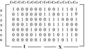
G = [I: X]where I is a k × k = 7 x 7 identity matrix and
X is a k×(n−k) = 7 x 8 matrix that generates the parity-bits
Figure 4.1(a) Generator Matrix for the (15, 7, 5)EG-LDPC in Systematic Format
Fig. 4.1(a) shows the systematic generator matrix to generate (15, 7, 5) EG-LDPC code. The encoded vector consists of information bits followed by parity bits, where each parity bit is simply an inner product of information vector and a column of X, from G = [I: X]
Figure 4.1(b) Structure of an Encoder Circuit for the (15, 7, 5) EG-LDPC Code
Figure 4.1(b) shows the encoder circuit to compute the parity
bits of the (15, 7, 5) EG-LDPC code. In this figure I = ( i0
,i1,…..i6 ) is the information vector and will be copied to C = (
c0,…………c6 ) bits of the encoded vector C, and the rest of
encoded vector, the parity bits, are linear sums (XOR) of the information bits. If the building block is two-input gates then the encoder circuitry takes 22 two-input XOR gates. Once the XOR functions are known, the encoder structure is very similar to the detector structure shown in Fig.3, except it consists of (n-k) XOR gates of varying numbers of inputs. Each nano wire-based XOR gate has structure similar to the XOR tree shown in Figure 4.1(b).[10]
4.2. Fault Secure Detector
Figure 4.2 Fault Secure Detector
5. RESULTS AND CONCLUSION
The information bits are fed into the encoder to encode the information vector, and the fault secure detector of the encoder verifies the validity of the encoded vector
THEORITICAL CALCULTION: 7-bit information vector is applied to encoder module as shown below.
Input message vector = m6 m5 m4 m3 m2 m1 m0.=000 0010 The encoded vector consists of information bits followed by parity bits.
Codeword = [C0 C1 …. C14]
C = [I:P]; I = Message Part;
p = Parity Part; P = [p0, p1, p2, p3, p4, p5, p6, p7]
p0= m0 xor m4 xor m6 =0 + 0 + 0 =0 ;
p1= m0 xor m1 xor m4 xor m5 xor m6 = 0+1 +0 +0+0 = 1;
p2=m0 xor m1 xor m2 xor m4 xor m5 = 0+ 1 +0 +0+0 = 1; p3=m1 xor m2 xor m3 xor m5 xor m6 = 0+ 1 +0 +0+0 = 1; p4=m0 xor m2 xor m3 = 0 +0+0 = 0;
p5=m1 xor m3 xor m4 = 1+0 +0 = 1; p6=m2 xor m4 xor m5 = 0+0+0 = 0; p7=m3 xor m5 xor m6 = 0 +0+0 = 0; code word=(0000 0010 0111 0100);
The checking or detecting operation is the following
vector-matrix multiplication S = C×HT ,
Syndrome vector is zero if c is a valid codeword and non-zero if c is an erroneous codeword.
S =0000 0000
Hence received codeword is valid code word.
REFERENCES
[1] ITRS, “International technology roadmap for
semiconductors,”2005.[Online].Available:
http://www.itrs.net/Links/2005ITRS/Home2005.htm
[2] Y. Chen, G.-Y. Jung, D. A. A. Ohlberg, X. Li,
[image:5.595.77.220.157.239.2] [image:5.595.35.289.338.400.2] [image:5.595.335.519.434.585.2]© 2016, IRJET | Impact Factor value: 4.45 | ISO 9001:2008 Certified Journal
| Page 1554
molecular-switch crossbar circuits,”
Nanotechnology, vol.14, pp. 462–468, 2003.
[3] Y. Chen, D. A. A. Ohlberg, X. Li, D. R. Stewart, R. S.
Williams,J. O. Jeppesen, K. A. Nielsen, J. F. Stoddart, D. L. Olynick, and E.Anderson, “Nanoscale molecular-switch devices fabricated by imprintlithography,” Appl. Phys. Lett., vol. 82, no. 10, pp. 1610– 1612, 2003.
[4] A. DeHon, “Deterministic addressing of nanoscale
devices assembledat sublithographic pitches,” IEEE Trans. Nanotechnol., vol. 4, no. 6, pp. 681–687, 2005.
[5] A. DeHon, “Nanowire-based programmable
architectures,” ACM J.Emerging Technol. Comput. Syst., vol. 1, no. 2, pp. 109–162, 2005.
[6] A. DeHon, S. C. Goldstein, P. J. Kuekes, and P. Lincoln,
“Non-pho- tolithographic nanoscale memory density prospects,” IEEE Trans. Nanotechnol., vol. 4, no. 2, pp. 215–228, Feb. 2005.
[7] A. DeHon and M. J. Wilson, “Nanowire-based
sublithographic pro-grammable logic arrays,” in Proc. Int. Symp. Field-Program. Gate Ar- rays, Feb. 2004, pp. 123– 132.
[8] M. Forshaw, R. Stadler, D. Crawley, and K. Nikolic ´, “A
short re-view of nanoelectronic architectures,”
Nanotechnology, vol. 15, pp. S220–S223, 2004.
[9] R. G. Gallager, Low-Density Parity-Check Codes.
Cambridge, MA:MIT Press, 1963.
[10]J. E. Green, J. W. Choi, A. Boukai, Y. Bunimovich, E.
John-MITPress,1963.
BIOGRAPHIES
P.Kanvitha has received her Bachelor of Technology (B.Tech) Degree from Chalapathi Institute of Engineering and Technology in Electronics and Communication Engineering in the year 2015 . Now she is presently pursuing her Master of Technology (M.Tech) degree from
Chalapathi Institute of
Engineering and Technology in VLSI and Embedded systems. Her area of interest includes Signal processing, VLSI design and Embedded systems
N.Naga Raju has received his Master of Technology (M.Tech)
degree from IIIT D&M
Kancheepuram in Communication Systems in the year 2014 and he
received his Bachelor of
Technology (B.Tech) degree from R .V. R & J .C
College of Engineering in Electronics and Communication Engineering in the year 2010.Now he is currently working as Assistant Professor in Department
of Electronics and
Communication Engineering in Chalapathi Institute of Engineering and Technology. His area of research includes
Signal processing, Image
processing and wireless