ISSN 2250-3153
Design and Implementation Memory Module for Air
Conditioners
Abhinav Parashar#1, Aditya Vineet#2 #
Department of Electronics and Communication Engineering, Delhi Technological University, Delhi – 110042
1[email protected] 2 [email protected]
DOI: 10.29322/IJSRP.9.01.2019.p8535
http://dx.doi.org/10.29322/IJSRP.9.01.2019.p8535
Abstract — This project includes the Design and
Implementation Memory Module for Air Conditioners using embedded C language and it synthesis using Arduino software on a ATMEGA Microcontroller board. The implementation strategies have been designed in such a way so as to keep the functioning of the system simple yet an efficient one. The instruction set adopted here is extremely simple that complements the architecture in completing the defined task. The complete architecture has been divided into two different entities or modules. One of the module in a primitive sense resembles the control panel of an Air Conditioning unit. The LCD display shows different settings such as temperature set and timer set. The Auxiliary module contains a Microcontroller board which works in conjunction with the main module. An added feature of the system is that every unit of architecture has been well thought upon and is the most efficient one according to our knowledge. The code has been written on the Arduino IDE and the code occupies moderate amount of available memory. All the aspects of the problem statement have been completely realized and the given objective has been fulfilled without adding any significant amount of cost. Code is fairly easy to understand and is in sync with most of the functions from C++ language.
Keywords —
INTRODUCTION
In an age when technological innovations are breaking all the barriers to conventional means and causing a complete
paradigm shift, automation is one area which seems to be a clear front runner.
India happens to be a nation of massive consumption. With all the demand come all the problems associated with it. Since the older times people have tried to solve their unexpected problems using many unexpected ways and have often found considerable success. As times have changed and humanity has evolved, the type of problems may have become complex but they still are unexpected in a lot of ways. With all the increased indulging, at times people face problems, which maybe the strangest, but may affect them in lot many ways
One such problem is the loss of power. If one has to argue, then it can be clearly identified that the single largest contributor to the technology as a phenomenon has been electricity. It was only time someone identified how to store electricity and make it available when not available. But still there are many large devices who can't work on a conventional inverter/generator used for providing power backup.
ISSN 2250-3153
user if the power situation is rather erratic in the area here he/she uses the AC.
Our project aims to eliminate this very problem by adding an additional self-sustaining unit which runs on its own DC power.
BASIC TERMINOLOGIES
A. General Purpose PCBs
General purpose PCBs, as their name suggests is the generalized from of PCB. By generalized we mean that
we are free to make any
kind of circuit as we wish
using this PCB. This makes it
useful for small scale
production of
electronic devices and also for
testing out new ideas before
production. Like a
normal PCB, it provides a
means to hold all of our components together in one place as a single unit. But it does not provide the connection between components as provided by a specific purpose PCB using tracks.
So the users have to make the
connections their self-using wires or solder joints. They have holes all over it in a grid like pattern, unlike a specific purpose PCB which only have holes where required. So in a general purpose PCB, you can place components anywhere you like. The image below show both the front and the back side of a general purpose PCB
B. ATMega328P Micro-controller
It is one of the most commonly used microcontrollers for industry related projects. This is a high-performance 8-bit microchip, made by ATMEL and is a RISC-based microcontroller. It combines 32KB ISP flash memory with read-while-write capabilities, 1024B EEPROM, 2KB SRAM, 23 general purpose I/O lines, 32 general purpose working registers, three flexible timer/counters with compare modes, internal and external interrupts, serial programmable USART, a byte-oriented 2-wire serial interface, SPI serial port, a 6-channel 10-bit A/D converter (8-channels in TQFP and QFN/MLF packages), programmable watchdog timer with internal oscillator, and five software selectable power saving modes. The device operates between 1.8-5.5 volts.
By executing powerful instructions in a single clock cycle, the device achieves throughputs approaching 1 MIPS per MHz, balancing power consumption and processing speed.
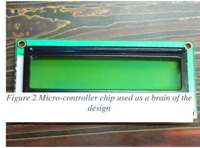
C. LCD Display
LCD (Liquid Crystal Display) screen is an electronic device used for a wide array of applications. It is a very basic module and is of the size of 16x2, very commonly used in various devices and circuits. As they bare economical, easily programmable, highly efficient and have no limitation of displaying special & even custom characters (unlike in seven segments), animations, they are preferred over a conventional LED matrix segment and/ or a seven segment display..
[image:2.595.320.527.110.263.2]Figure 1 PBC used to implement the hardware controller
ISSN 2250-3153
A 16x2 LCD means it can display 16 characters per line and there are 2 such lines. In this LCD each character is displayed in 5x7 pixel matrix. This LCD has two registers, namely, Command and Data. The command register stores the command instructions given to the LCD. A command is an instruction given to LCD to do a predefined task like initializing it, clearing its screen, setting the cursor position, controlling display etc. The data register stores the data to be displayed on the LCD. The data is the ASCII value of the character to be displayed on the LCD.
PROPOSED DESIGN
A.
Architecture
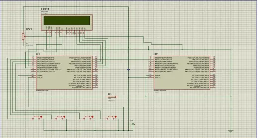
The proposed design includes:
• A transmitter-receiver pair (in the form of Arduinos) used to exchange the setup data whenever required
• Tx and Rx pin of the micro-controllers are connected to establish a half-duplex communication protocol.
• Common ground is given to the gnd terminal of both the controllers via a resistor to avoid noise/disturbances.
• 5V power supply is given to both the Microcontroller units.
• Main unit draws its power from the A C power supply, whereas the auxiliary unit uses a DC- battery operated power source.
• 16x2 LCD for the display of readings of both the transmitter as well as the receiver
VSS and R/W pin of the LCD are connected to gnd terminal
VDD pin is connected to 5V
[image:3.595.38.563.227.506.2] D4,D5,D6 and D7 pin of both the LCD are connected to the respective micro-controllers for data input
ISSN 2250-3153
Enable(E) and Reset(RS) pins are connected to the respective micro-controllers for enabling the LCDs
• Controlling Switch pad which is used to increase or decrease the temperature reading of the A.C. and also the number of hours for which A.C. is to be kept on
S1 is used to increase the temperature S2 is used to decrease the temperature S3 is used to increase the number of hours S4 is used to decrease the number of hours
B.
Working
• When the AC supply is available:
Main Unit of the Memory Module receives the input commands and stores the temperature data readings, number of hours and several other functionality.
All this data can be modified manually using the control panel provided on the top of the system.
For simplicity initially we decided to use two types of numeric readings, that is Temperature set and Timer value. If the user
modifies these values then it can set
them
within a range: 16 C-31 C (for Temperature) and 0-15 hrs (Timer). The default values for the setup is 16 C (for Temperature) and 0 hrs for (Timer). The timer value gets decreased every hour and is the correspondingly updated on the LCD panel provided.
The Auxiliary Unit, at all time, receives the data that is being fed to the main unit, holds it and reflects any update on the main unit, acting as a slave. It has its own power supply, which is provided by a set of batteries, which provide a DC power source.
Thus the system shown is a complete replica of an Air Conditioning control panel but contains an auxiliary microcontroller unit now visible to the user.
• When the Electric Power is cut:
Main Unit gets switched off as it is directly AC driven. This generates a signal instantly to trigger the Auxiliary Unit
Auxiliary Unit, being operated using a DC battery starts to act as a master now, holding the last updated value starts sending the main unit its last updated value.
As soon as the Main unit starts functioning when the power arrives, it may choose to accept the data being sent by the Auxiliary unit for some time and then start functioning normally.
The choice of accepting the data is based on a signal which canbe given by pressing a button by the user when it configures its settings.
This button makes the system differentiate a normal shutdown of the Air Conditioner unit from an unexpected power loss
ISSN 2250-3153
Following are some of the key aspects of the proposed design:
• Initially made for an Air Conditioning unit
• Easy installation
• Arduino based microcontroller system
• Dual Mode- Temperature and Timer retention
• Complete in built system with no extra hardware required
• Flexibility in terms of time until memory retention
D. OUTCOME OBTAINED
The output presents the following observations:
• All the signals represented are dynamic and can be modified by the user from the system.
• The user is able to set the configuration of the system, whether he/she wants to switch ON the special feature of memory retention by pressing a button.
• If activated, all the four LEDs on the control panel glow, during the event of a power failure.
• The user can set the values of both the parameters to whatever value within the permissible limits and is able to retrieve them even after a power failure.
FUTURE SCOPE
• Wireless Remote Access
Currently, the input to the module is designed as a wired system with a keypad with buttons to control/setup the temperature of the Air Conditioner and also to setup the number of hours and it is correspondingly reflected on the LCD display.
This module may be made completely wireless by including a Tsop Sensor Module which acts as an IR sensor and can be interfaced with the Remotes used to control the electronics devices wirelessly.
Other efficient ways to implement remote control can also be implemented like Bluetooth, Wi-Fi, GSM etc.
• Battery for Auxiliary Unit
The Auxiliary Module currently runs on a DC battery which needs to be replaced time to time.
Later, this may be replaced by rechargeable batteries and a system may be design to charge during the idle time to
Auxiliary unit. This will not only make the system more durable but also will make it more reliable.
• Other Practical Uses
The project finds use in many other places which may need this kind of data saving system.
Some of these applications are in:
Cars: For saving user data on the stereo or on car panel, such as cruise control, Bluetooth settings. Television: Here also the system can be used to save
user settings regarding channel settings, recorded programs, etc.
CHALLENGES COMABTED
• Multiple Data Handling
One of the major issues with the implementation of the project was the presence of multiple data arising from multiple signals. As the main module continuously sends data to the auxiliary module, therefore the system had to be such that there was a clear distinction between the data sent and data interpreted by the receiver.
• Trigger for Auxiliary Unit
Another issue was to implement a clear trigger which acts whenever the auxiliary unit has to resend the last updated value to the main unit. The trigger had to be such that is should not get affected by the power loss and should be able to work such that the main unit accepts the data being sent by the auxiliary one when it restarts after the power loss.
• LCD Issues
LCD screen must be able to show the correct data whenever it starts. This means it should remain OFF during power loss and should have no connection with the DC power source.
RESULTS AND CONCLUSION
ISSN 2250-3153
simultaneously more user engaging. Systems providing smart yet efficient solutions play an important role in bridging the urban and sub-urban factions of the technological world. Everywhere we see research is being done to improve user experience and at the same time increase the functionality, security, and efficiency of the systems. With advances in technology, many researchers have tried and are trying to design systems which offer either of the following design targets – highly functional, compact, low power consumption, regularity of layout and hence less area or even combination of them in a single system thus making them suitable for various in-house appliances.
A smart and an innovative system has always been a fundamental requirement of modern technological systems. Along with it the circuit architecture should be simple and area-efficient.
In embedded systems the aim of the project is usually to develop a system which presents to you a working prototype and can be easily engulfed into a main system and yet causing a little or no interference to its functioning. Our project implementation has been on this very principle. It aims to be a small part of a very large and a highly complex system but it aims to increase the user experience manifold. By providing a self-sustaining unit which can be just plugged in, it implies we have checked most of the boxes, when it comes to implementing an embedded system.
The working model is only a small prototype and provides us with a large scope of expansion in terms of number of features, functions and other aspects of it.
REFERENCES
1. ATMEL AVR architecture-datasheet
2.
archive.fabacademy.org/2017/fablabbcn/students/108/week1.h tm
3.
https://www.jameco.com/Jameco/Products/ProdDS/847252.pd f
4.
digital-wizard.net/practical_electronics/general_purpose_pcb
5. https://www.engineersgarage.com/electronic-components/16x2-lcd-module-datasheet