Programmer's Utilities Guide
For
the
CP/M® Family of
Ogerating Systems
. ; _ ~ 4
[Q]
DIGITAL
RESEARCHTM
Programmer's Utilities Guide
COPYRIGHT
Copyright © 1982 by Digital Research. All rights reserved. No part of this publica-tion may be reproduced, transmitted, transcribed, stored in a retrieval system, or translated into any language or computer language, in any form or by any means, electronic, mechanical, magnetic, optical, chemical, manual or otherwise, without the prior written permission of Digital Research, ,Post Office Box 579, Pacific Grove, California, 93950.
This manual is, however, tutorial in nature. Thus, the reader is granted permission to include the example programs, either in whole or in part, in his own programs.
DISCLAIMER
Digital Research makes no representations or warranties with respect to the contents hereof and specifically disclaims any implied warranties of merchantability or fitness for any particular purpose. Further, Digital Research reserves the right to revise this publication and to make changes from time to time in the content hereof without obligation of Digital Research to notify any person of such revision or changes.
TRADEMARKS
CPIM is a registered trademark of Digital Research. ASM, DDT, LIB-80, LINK-80, MAC, MPIM II, PL/I-80, RMAC, and SID are trademarks of Digital Research. XREF is a utility of Digital Research. Intel is a registered trademark of Intel Corporation. Microsoft is a registered trademark of Microsoft Corporation. Z80 is a registered trademark of Zilog, Inc.
The Programmer's Utilities Guide for the CP 1M Family of Operating Systems was prepared using the Digital Research TEX Text Formatter and printed in the United States of America.
Programmer's Utilities Guide
for the CP/Y@ Faaily of Operating Systeas Release Notes
Addendua to the Pirat printing--1982
Copyright© 1982 by Digital Research
CPIM is a registered trademark of Digital Research. LINK-80 and MP/H are trademarks of Digital Research.
Compiled December 1982
The following LINK-80N ~9tion switches are not documented in
Section 15.4 of The Programmer's Utilities Guide for the CP/H@
Family of Operating Systems.
~he BIOS Link (B) Switch
The 8 switch is used to link a 8IOS in a banked CP/M 3 system. LINK-80 aligns the data segment on a page boundary, puts the length of the code segment in the header, and defaults to the SPR filetype.
The Output RSP Pile (OR) Switch
The OR switch outputs RSP (Resident System Process) files for execution under MP/MTM •
~he Output SPR Pile (OS) Switch
The OS switch outputs SPR (System Page Relocatable) files for excution under HP/H.
All Information Presented Here is proprietary to Digital Research
Foreword
This manual describes several utility programs that aid the programmer and system designer in the software development process. Collectively, these utilities allow you to assemble 8080 assembly language modules, link them together to form an execut-able program, and generate a cross-reference listing of the variexecut-ables used in a pro-gram. With these utilities, you can also create and manage your own libraries of object modules, as well as create large programs by breaking them into separate overlays.
The Programmer's Utilities Guide assumes you are familiar with the CP IM® or MP 1M IITM Operating System environment. It also assumes you are familiar with the
basic elements of assembly language programming as described in the 8080 Assembly Language Programming Manual, published by Intel®.
MAC™, the CP/M macro assembler, translates 8080 assembly language statements and produces a hex format object file suitable for processing in the CP/M environ-ment. MAC is upward compatible with the standard CP/M nonmacro assembler, ASM™. (See the CP/M documentation published by Digital Research.)
MAC facilities include assembly of Intel 8080 microcomputer mnemonics, along with assembly-time expressions, conditional assembly, page formatting features, and a pow-erful macro processor compatible with the standard Intel definition. MAC also accepts most programs prepared for the Processor Technology Software # 1 assembler, requiring only minor modifications. This revision is not compatible with previous versions.
MAC is supplied on a standard disk, along with a number of library files. MAC requires about 12K of machine code and table space, along with an additional 2.SK
of I/O buffer space. Because the BDOS portion of CP/M is coresident with MAC, the minimum usable memory size for MAC is about 20K. Any additional memory adds to the available Symbol Table area, allowing larger programs to be assembled.
Sections 1 through 5 describe the simple assembler facilities of MAC: 8080 mne-monic forms, expressions, and conditional assembly. These facilities are similar to those of the CP/M assembler (ASM). If you are familiar with ASM, you might want to skip Sections 1 through 5 and begin with Section 6.
Sections 6 through 8 describe MAC macro facilities in detail. Section 7 describes inline macros, and Section 8 explains the definition and evaluation of stored macros.
If you are familiar with macros, briefly skim these sections, referring primarily to the examples. Section 9 explains macro applications, common macro forms, and pro-gramming practices. Skim the examples and refer back to the explanations for a detailed discussion of each program.
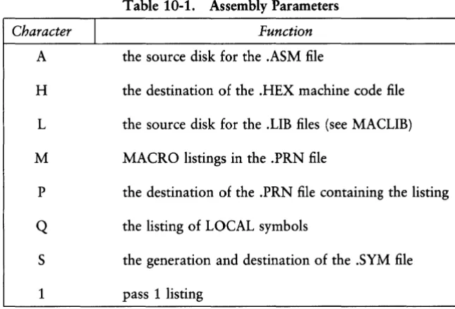
Sections 10 through 13 describe other features of macro ,assembler operation. Sec-tion 10 details assembly parameters. SecSec-tion 11 introduces iterative improvement, a common debugging practice used in developing macros and macro libraries. Section 12 defines MAC's symbol storage requirements.
Section 13 explains the differences between MAC and RMAC™, the CP/M Relo-cating Macro Assembler.
Section 14 details XREF, an assembly language cross-reference program used with MAC and RMAC.
Section 16 describes LINK-80™, the linkage editor that combines relocatable object modules into an absolute file ready to run under CP/M or MP/M II. Section 17 describes how to use LINK-80, in conjunction with the PL/I-80™ compiler, to pro-duce overlays. Section 18 explains how to use LIB-80™, the software librarian for creating and manipulating library files containing object modules.
The appendixes contain a complete list of error messages output by each of the utility programs.
Table of Contents
1 Macro Assembler Operation. . . .. . . .. . . .. . . .. . . 1
2 Program Format. . . 3
3 Forming the Operand 3.1 Labels ... . . . 5
3.2 Numeric Constants ... 6
3. 3 Reserved Words ... 7
3.4 String Constants ... . . . 8
3.5 Arithmetic, Logical, and Relational Operators ... 8
3.6 Precedence of Operators ... 11
4 Assembler Directives 4.1 The ORG Directive ... 14
4.2 The END Directive ... 14
4.3 The EQU Directive ... 15
4.4 The SET Directive ... . . . 16
4.5 The IF, ELSE, and ENDIF Directives ... 16
4.6 The DB Directive ... 21
4.7 The OW Directive ... 22
4.8 The OS Directive ... 23
4.9 The PAGE and TITLE Directives ... 23
4. lOA Sample Program Using Pseudo Operations ... 25
5 Operation Codes 5.1 Jumps, Calls, and Returns ... 30
5.2 Immediate Operand Instructions ... 32
Table of Contents
(continued)
5.3 Increment and Decrement Instructions ... 33
5.4 Data Movement Instructions ... 34
5.5 Arithmetic Logic Unit Operations ... 37
5.6 Control Instructions ... 39
An Introduction to Macro Facilities Inline Macros 7.1 The REPT-ENDM Group ... 49
7.2 The IRPC-END M Group ... 51
7.3 The IRP-ENDM Group... 54
7.4 The EXITM Statement ... 58
7.5 The LOCAL Statement ... 60
8 Definition and Evaluation of Stored Macros 8.1 The MACRO-ENDM Group ... 66
8.2 Calling a Macro ... 66
8.3 Testing Empty Parameters ... 72
8.4 Nested Macro Definitions ... 76
8.5 Redefinition of Macros ... ~ . . . 79
8.6 Recursive Macro Invocation ... 82
8.7 Parameter Evaluation Conventions ... 84
8.8 The MACLIB Statement ... 92
9 Macro Applications 9.1 Special Purpose Languages ... 95
9.2 Machine Emulation ... 108
Table of Contents
(continued)
9.3 Program Control Structures ... 145
9.4 Operating System Interface ... 180
10 Assembly Parameters 11 Debugging Macros 12 Symbol Storage Requirements 13 RMAC, Relocating Macro Assembler 13.1 RMAC Operation ... 231
13.2 Expressions ... 232
13.3 Assembler Directives ... 232
13.3.1 The ASEG Directive. . . .. . . .. 233
13.3.2 The CSEG Directive ... 233
13.3.3 The DSEG Directive ... 233
13.3.4 The COMMON Directive ... 233
13.3.5 The PUBLIC Directive ... 234
13.3.6 The EXTRN Directive ... 234
13.3.7 The NAME Directive ... 234
14 XREF 15 LINK-80 15.1 Introduction ... 237
15.2 LINK-80 Operation ... 238
15.3 Multiline Commands ... 238
Table of Contents
(continued)
15.4 LINK-80 Switches ...•... 239
15.4.1 The Additional Memory (A) Switch ... 239
15.4.2 The Data Origin (D) Switch ... 240
15.4.3 The Go (G) Switch ... 240
15.4.4 The Load Address (L) Switch ... 240
15.4.5 The Memory Size (M) Switch ... 241
15.4.6 The No List (NL) Switch ... 241
15.4.7 The No Recording of Symbols (NR) Switch ... 241
15.4.8 The Output COM File (OC) Switch ... 241
15.4.9 The Output PRL File (OP) Switch ... 241
15.4.10 The Program Origin (P) Switch ... 241
15.4.11 The ? Symbol (Q) Switch ... 242
15.4.12 The Search (S) Switch ...•... 242
15.5 The $ Switch ... 242
15.5.1 $Cd-Console ... 243
15.5.2 $Id-Intermediate... . . .. . . .. . . .. 243
15.5.3 $Ld-Library ... 243
15.5.4 $Od-Object ... 243
15.5.5 $Sd-Symbol ...•... 243
15.5.6 Command Line Specification ... '. . . . .. 244
15.6 Creating MP 1M II PRL Files ... 244
15.7 The Request Item ... ;... 245
15.8 REL File Format ... " . . . .. 246
15.9 IRL File Format ...•... 248
16 Overlays 16.1 Introduction ... 251
16.2 Using Overlays in PL/I Programs ... 252
16.2.1 Overlay Method 1 ... 252
16.2.2 Overlay Method 2 ... 254
16.3 Specifying Overlays in the Command Line ... 255
16.4 Sample LINK-80 Execution ... 256
Table of Contents
(continued)
16.5 Other Overlay Systems ... 259
17 LIB-SO
17.1 Introduction ... 261 17.2 LIB- 80 Operation ... 261 17.3 LIB-80 Switches ... 263
Table of Contents
(continued)
Appendixes
A MAC/RMAC Error Messages ... 265
B XREF Error Messages ... 269
C LINK-80 Error Messages ... 271
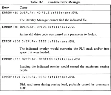
D Overlay Manager Run-time Error Messages ... 275
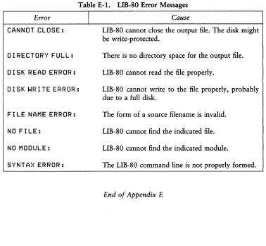
E LIB- 80 Error Messages . . . .. 277
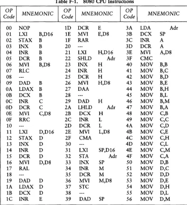
F 8080 CPU Instructions ... 279
Table of Contents
(continued)
List
of Tables
3-1. 8080 Registers and Values ... 7
3-2 Operators. . . .. . . .. . . .. . . .. . . .. . . . 9
3-3. Equivalent Forms of Relational Operators ... 12
4-1. Pseudo Operations ...•... 13
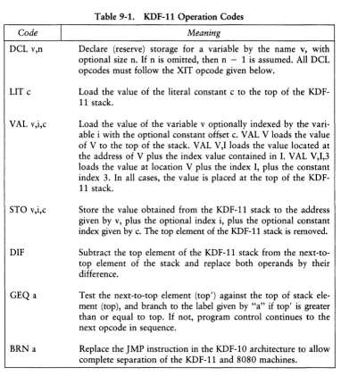
9-1. KDF-11 Operation Codes ... 120
10-1. Assembly Parameters ... 221
17-1. LIB-80 Switches ... 0 • • • • • • • • • • • • • • • • • • • • 0 • • 0 • • • • • • • • 263 A-1. MAC/RMAC Error Messages . 0 • • • • • • • • • • • • • • • • • • • • 0 " 0 . . . 265
A-2 Terminal Error Conditions .... 0 • • • • • • • • • ~ • • • • • • • • • • 0 • • 0 • • • • • • • • 267 B-1. XREF Error Messages ... 0 • • • • • • • • • • • • • • • • • • • • 0 • • 0 • • • • • • • • 269 C-1. LINK-80 Error Messages ... 0 • • 0 • • • • • • • • 271 D-1. Run-time Error Messages ...
0 ... 0...
275E-1. LIB-80 Error Messages ... 0 • • 0 • • • • • • • • 277 F-1. 8080 CPU Instructions ... 0 • • • • • • • • 279
List of Figures
15-1. IRL File Index ... 0 • • 0 • • 0 • • • • • 248 16-1. Tree-structured Overlay System 0 • • • • • • • • • • • • • • • • • • • 0 • • • 0 • • • • • • • • 251 16-2 Separate Overlay System ... 0 • • • • • • • • 258List of Listings
1-1. Sample ASM, PRN, SYM, and HEX files from MAC ... 14-1. Conditional Assembly with TTY True ... 0 • • 0 • • • • • • ; • 17 4-2 Conditional Assembly with TTY False ... 0 • • 0 • • • • • 18 4-3. Conditional Assembly Using ELSE for Alternate ... 0 • • 0 • • • • • • • • 19 4-4. Sample Program Using Nested IF, ELSE, and ENDIF . 0 • • 0 • • • • • • • • 21 4-5. TYPER Program Listing ... 0 . . . 0 0 • • 0 . . . 26
5-1. Assembly Showing Jumps, Calls, Returns, and Restarts 0 • • 0 • • • • • • • • 31 5-2 Assembly Using Immediate Operand Instructions ... 0 • • • • • • • • 33 5-3. Assembly Containing Increment and Decrement Instructions ... 34 5-4. Assembly Using Various Register IMemory Moves ... 0 • ' 0 • • • • • 36
5-5. Assembly Showing ALU Operations ... 0 • • • • • • • • 38
Table of Contents
(continued)
6-1. A Sample Macro Library ... 43
6-2 A Sample Assembly Using the MAC LIB Facility ... 45
7-1. A Sample Program Using the REPT Group ... 50
7-2a. Original (.ASM) File with IRPC Example ... 52
7-2b. Resulting (.PRN) file with IRPC Example ... 53
7-3. A Sample Program Using IRP ... ~ . . . .. . . 57
7-4. Use of the EXITM Statement in Macro Processing ... 59
7-5a. Assembly Program Using the LOCAL Statement ... 62
7-Sb. Output from Program of Listing 7-5a. ... 63
8-1. Example of Macro Definition and Invocation ... 69
8-2 Sample Message Printout Macro ... 71
8-3. Sample Program Using the NUL Operator ... 74
8-4. Sample Program Showing a Nested Macro Definition ... 78
8-5. Sample Program Showing Macro Redefinition ... 80
8-6. Sample Program Showing a Recursive Macro ... 83
8-7. Macro Parameter Evaluation Example ... 87
8-8. Parameter Evaluation Using Bracketed Notation ... 89
8-9. Examples of Macro Parameter Evaluation ... 91
9-1. Macro Library for Basic Intersection ... 98
9-2a. Macro Library for Treadle Control ... 100
9-21>. Macro Library for Corner Pushbuttons ... 100
9-3a. Traffic Control Algorithm Using -M Option ... 102
9-3b. Intersection Algorithm with l~M in Effect ... 103
9-3c. Algorithm with Generated Instructions ... 104
9-4. Library Segment with Debug Facility ... 106
9-5a. Sample Intersection Program with Debug ... 107
9-5b. Debug Trace Printout ... 107
9-6. A-D Averaging Program Using Stack Machine ... 110
9-7. Stack Machine Opcode Macros ... 111
9-8. Averaging Program with Expanded Macros ... 114
9-9. Averaging Program with Debugging Statements ... 117
9-10. Sample Execution of AVER Using DDT. . . .. . . .. 119
9-11. Stack Machine Macro Library ... 121
9-12. Program for Tool Travel Computation ... 139
9-13. Sample Execution of Distance Using DDT ... 143
9-14. Partial Listing of Distance with Full Trace ... 144
9-1S. Simple 1/0 Macro Library ... 147
9-16. Macro Library for Simple Comparison Operations ... 148
9-17a. 9-171>. 9-18. 9-19a. 9-19b. 9-20.
9-21a~
9-21h. 9-22 9-23a. 9-23h. 9-24a. 9-24h. 9-25a. 9-25h. 9-25c. 9-26. 9-27. 9-28. 9-29. 9-30. 9-31. 9-32 16-1. 16-2
Table of Contents
(continued)
Single Character Processing using COMPARE. . . .. . .. . .. 150
Partial Trace of Listing 9-17a with Macro Generation ... 152
Expanded NCOMPARE Comparison Operators ... 153
Sample Program using NCOMPARE Library ... 156
Segment of Listing 9-19a with +M Option ... 157
Macro Library for the WHEN Statement ... 161
Sample WHEN Program with -M in Effect ... 162
Partial Listing of Listing 9-21a with +M Option ... 163
Macro Library for the DOWHILE Statement ... 165
An Example Using the DOWHILE Statement ... 167
Partial Listing of Listing 9-23a with Macro Generation ... 168
Macro Library for SELECT Statement ... 171
Library for SELECT Statement ... 172
Sample Program Using SELECT with -M +S Options... ... 174
Segment of Listing 9-25a with Mnemonics ... 175
Segment of Listing 9-25a with +M Option ... 176
Program Using WHEN, DOWHILE, and SELECT ... 179
Lower- to Upper-case Conversion Program ... 186
Sequential File Input/Output Library ... 188
Sample FILE Expansion Segment ... 202
Program for Line Printer Page Formatting ... 208
File Merge Program ... 211
Sample MERGE Disk Files ... 219
LINK-80 Console Interaction ... 258
Console Interaction with ROOT ... 258
Section 1
Macro Assembler Operation
Start MAC with a command of the form:
MAC filename
where filename corresponds to the assembly language file with an assumed filetype ASM. During the translation process, MAC creates a file called filename. HEX con-taining the machine code in the Intel hexadecimal format. You can subsequently load or test this HEX file. (See the LOAD command and the Dynamic Debugging Tool, DDT™, in the CP/M documentation.) MAC also creates a file named filename.PRN containing an annotated source listing, along with a file called filename.SYM contain-ing a sorted list of symbols defined in the program.
Listing 1-1 provides an example of MAC output for a sample assembly language program stored on the disk under the name SAMPLE.ASM. Type MAC SAMPLE followed by a carriage return to execute the macro assembler. The PRN, SYM, and HEX files then appear as shown in the listing. The assembler listing file (PRN) includes a 16-column annotation at the left showing the values of literals, machine code addresses, and generated machine code. Note that an equal sign (=) is used to denote literal values to avoid confusion with machine code addresses. (See Section 4.3.) Output files contain tab characters (ASCII CTRL-I) whenever possible to con-serve disk space.
Source Program (SAMPLE.ASM)
org 100h ;transient prOgraM area
bdos equ 0005h ;bdos entrY point
wchar equ 2 ;write character function
enter with ccp's return address in the stacK write a single character (?) and return ITll} i
ITll} i call
ret end
c t' .... char
e t '? ' bdos
100h
;write character function ;character to write
;write the character ;return to the ccp ;start address is 100h
Listing 1-1. Sample ASM, PRN, SYM, and HEX files from MAC
1 Macro Assembler Operation Programmer's Utilities Guide
0100 0005 0002
0100 OE02 0102 lE3F 0104 CD0500 0107 C8 0108
0005 BOOS
Assembler Listing File (SAMPLE.PRN)
ORG 100H jTRANSIENT PROGRAM AREA
BOOS EQU 0005H JBDOS ENTRY POINT
WCHAR EQU 2 jWRITE CHARACTER FUNCTION
ENTER WITH CCP'S RETURN ADDRESS IN THE STACK WRITE A SINGLE CHARACTER (?) AND RETURN MVI C,WCHAR jWRITE CHARACTER FUNCTION MVI E, '?' jCHARACTER TO WRITE CALL BOOS jWRITE THE CHARACTER
RET jRETURN TO THE CCP
END 100H jSTART ADDRESS IS 100H
Assembler Sorted Symbol File (SAMPLE.SYM)
0002 WCHAR
Assembler Hex Output File (SAMPLE. HEX)
:080100000E021E3FCD0500C8EF :00010000FF
Listing 1-1. (continued)
End of Section 1
Section 2
Program Format
A program acceptable as input to the macro assembler consists of a sequence of statements of the form
line# label operation operand comment
where any or all of the elements can be present in a particular statement. Each assembly language statement terminates with a carriage return and line-feed. Note that the ED program automatically inserts the line-feed when you enter a carriage return. You can also terminate an assembly language statement by typing the excla-mation point (!) character. MAC treats this character as an end-of-line. You can write multiple assembly language statements on the same physical line if you separate them with exclamation points.
A sequence of one or more blank or tab characters delimits statement elements. Tab characters are preferred because they conserve source file space and reduce the listing file size. The tab characters are not expanded until the file is printed or typed at the console.
The line# is an optional decimal integer value representing the source program line number. It is allowed on any source line. The assembler ignores the optional line#.
The label field takes the form:
identifier
or
identifier:
The label field is optional, except where noted in particular statement types.
The identifier is a sequence of alphanumeric characters: alphabetics, question marks, commercial at-signs, and numbers, the first character of which is not numeric. You can use identifiers freely to label elements such as program steps and assembler directives, but identifiers cannot exceed 16 characters in length.
2 Program Format Programmer's Utilities Guide
All characters are significant in an identifier, except for the embedded dollar sign
($) that you can use to improve name readability. Further, MAC treats all lower-case alphabetics in an identifier as though they were upper-case. Note that the colon (:) following the identifier in a label is optional. The following examples are all valid labels:
x xy
x? x y 1 :
xlx2 @123:
GamMa @GAMMA
x234$5G78$8012$345G:
lon!1$name
lon!1er$named$data ??@@abcDEF
?ARE$WE$HERE?
The operation field contains an assembler directive (pseudo operation), 8080 machine operation code, or a macro invocation with optional parameters. The pseudo opera-tions and machine operation codes are described in Section 5. Macro calls are dis-cussed in Section 6.
The operand field of the statement contains an expression formed from constant and label operands, with arithmetic, logical, and relational operations on these oper-ands. Properly formed expressions are detailed in Section 3.
A leading semicolon character denotes the comment field, which contains arbitrary characters until the next carriage return or exclamation point character. MAC reads, lists, and otherwise ignores comment fields. To maintain compatibility with other assemblers, MAC also treats statements that begin with an asterisk (*) in column one as comment lines.
The assembly language program is thus a sequence of statements of the form described above, terminated optionally by an END statement. The assembler ignores all statements following the END.
End of Section 2
Section 3
Forming the Operand
Expressions in the operand field consist of simple operands-labels, constants, and reserved words-combined into properly formed subexpressions by arithmetic and logical operators. MAC carries out expression computation as the assembly proceeds. Each expression produces a 16-bit value during the assembly. The number of signifi-cant digits in the result must not exceed the intended use. That is, if an expression is to be used in a byte move immediate (see the MVI instruction), the absolute value of the operand must fit within an 8-bit field. Instructions for each expression give the restrictions on expression significance.
3.1 Labels
A label is an identifier of a statement. The label's value is determined by the· type of statement it precedes. If the label occurs on a statement that generates machine code or reserves memory space, such as a MOV instruction or a DS pseudo opera-tion, then the label is given the value of the program address it labels. If the label precedes an EQU or SET, then the label is given the value that results from evaluat-ing the operand field. In a macro definition, the label is given a text value, a sequence of ASCII characters, that is the body of the macro definition. With the exception of the SET and MACRO pseudo operations, an identifier can label only one statement.
When a nonmacro label appears in the operand field, the assembler substitutes its 16-bit value. This value can then be combined with other operands and operators to form the operand field for an instruction. When a macro identifier appears in the operation field of the statement, the text stored as the value of the macro name is substituted for the name. In this case, the operand field of the statement contains actual parameters. These are substituted for dummy parameters in the body of the macro definition. Later sections give the exact mechanisms for defining, calling, and substituting macro text.
3.2 Numeric Constants Programmer's Utilities Guide
3.2 Numeric Constants
A numeric constant is
a
16-bit value in a number base. A trailing radix indicator denotes the base, called the radix of the constant. The radix indicators areB binary constant (base 2)
o
octal constant (base 8) Q octal constant (base 8) D decimal constant (base 10) H hexadecimal constant (base 16)Q
is an alternate radix indicator for octal numbers because the letter 0 is easily confused with the digit O. Any numeric constant that does not terminate with a radix indicator is assumed to be a decimal constant.A constant is composed of a sequence of digits, followed by an optional radix indicator, where the digits are in the appropriate range for the radix. Binary con-stants must be composed of 0 and 1 digits. Octal concon-stants can contain digits in the range 0-7. Decimal constants contain decimal digits. Hexadecimal constants contain decimal digits and hexadecimal digits A through F, corresponding to the decimal numbers 10 through 15.
Note that the leading digit of a hexadecimal constant must be a decimal digit to avoid confusing a hexadecimal constant with an identifier. A leading 0 prevents ambiguity. A constant composed in this manner produces a binary number that can be contained within a 16-bit counter, truncated on the right by the assembler. Like identifiers, embedded $ symbols are allowed within constants to improve readability.
Finally, the radix indicator translates to upper-case if a lower-case letter is encoun-tered. The following examples are valid numeric constants:
1234 1234H 33770
12340
OFFFEH
Ofe3h11006 33770 1234d
1111$0000$1111$00006 33$77$22Q
Offffh
Programmer's Utilities Guide 3.3 Reserved Words
3.3 Reserved Words
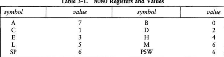
[image:23.469.62.433.139.233.2]Several reserved character sequences have predefined meanings in the operand field of a statement. The names of 8080 registers and their values are given in Table 3-1.
Table 3-1. 8080 Registers and Values
symbol
I
valueI
symbolI
valueA 7 B 0
C 1 D 2
E 3 H 4
L 5 M 6
SP 6 PSW 6
Lower-case names have the same values as their upper-case equivalents. Machine instructions can also be used in the operand field, resulting in their internal codes. For instructions that require operands, where the operand is a part of the binary bit pattern of the instruction (e.g., MOV A,B), the value of the instruction is the bit pattern of the instruction, with zeros in the optional fields. For example, the statement
L}{I HtMOl.J
assembles an LXI H instruction with an operand equal to 40H, the value of the MOV instruction with zeros as operands.
When the $ symbol appears in the operand field-not embedded within identifiers and numbers-its value is the address of the beginning of the current instruction. For example, the two statements
}{: JMP}-(
and
JMP $
produce a jump instruction to the current location. As an exception, the $ symbol at the beginning of a logical line can introduce assembly formatting instructions. (See Section 10.)
3.4 String Constants Programmer's Utilities Guide
3.4 String Constants
String constants represent sequences of graphic ASCII characters, enclosed in apos-trophes ('). All strings must be fully contained within the current physical line, with the exclamation point (!) character within strings treated as an ordinary string char-acter. Each individual string must not exceed 64 characters in length, or MAC reports an error. The apostrophe character can be included in a string by typing two apos-trophes ("). The assembler reads the two aposapos-trophes as a single apostrophe.
Note that particular operation codes can require the string length to be no longer than one or two characters. The LXI instruction, for example, accepts a character string operand of one or two characters. The CPI instruction accepts only a one-character string. The DB instruction, however, allows strings zero through 64 char-acters long in its list of operands. In the case of single-character strings, the value is the 8-bit ASCII code for the character, without case translation. Two-character strings produce a 16-bit value with the second character as the low-order byte and the first character as the high-order byte. For example, the string constant 'A' is equivalent to 41H. The two-character string 'AB' produces the 16-bit value 4142H. The following are valid strings in MAC statements:
'A '
'AB'
I a b ' , c ' ""
'she said IIhelloll 'Note: You can use the ampersand (&) character to cause evaluation of dummy arguments within macro expansions inside string quotes. Section 8 details the substi-tution process.
3.5 Arithmetic, Logical, and Relational Operators
MAC can combine the operands described above in algebraic notation using prop-erly formed operands, operators, and parenthesized expressions. The operators MAC recognizes in the operand field are listed below.
• a
+
b produces the arithmetic sum of a and b;+
b is b.• a - b produces the arithmetic difference between a and b; - b is 0 - b.
• a *b is the unsigned multiplication of a by b.
• alb is the unsigned division of a by b.
• a MOD b is the remainder after division of a by b.
• a SHL b produces a shifted left by b, with zero right fill.
Programmer's Utilities Guide 3.5 Operators
• a SHR b produces a shifted right by b, with zero left fill.
• NOT b is the bit-by-bit logical inverse of b.
• a EQ b produces true if a equals b, false otherwise.
• a L T b produces true if a is less than b, false otherwise.
• a LE b produces true if a is less than or equal to b, false otherwise. • a GT b produces true if a is greater than b, false otherwise.
• a GE b produces true if a is greater than or equal to b, false otherwise.
• a AND b produces the bitwise logical AND of a and b. • a OR b produces the bitwise logical OR of a and b.
• a XOR b produces the logical exclusive OR of a and b.
• HIGH b is identical to b SHR 8 (high-order byte of b).
• LOW b is identical to bAND OFFH (low-order byte of b).
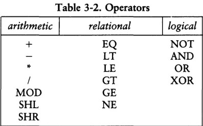
[image:25.469.146.345.374.498.2]The letters a and b represent operands that are treated as 16-bit unsigned quantities' in the range 0-65535. All arithmetic operators produce a 16-bit unsigned arithmetic result. Relational operators produce a true (OFFFFH) or false (OOOOH) 16-bit result. Logical operators operate bit-by-bit on their operands producing a 16-bit result of 16 individual bit operatioQ.s. The HIGH and LOW functions always produce a 16-bit result with a high-order byte of zero. Table 3-2 lists arithmetic, logical, and relational operators.
Table 3-2. Operators
arithmetic
I
relational+
*
/
MOD SHL SHR
EQ LT LE GT GE NE
/logical
NOT AND OR XOR
3.5 Operators Programmer's Utilities Guide
MAC performs all computations during the assembly process as 16-bit unsigned operations, as described above. The resulting expression must fit the operation code in which it is used. For example, the expression used in an ADI (add immediate) instruction must fit into an 8-bit field. Thus, the high-order byte must be zero. If the computed value does not fit the field, the assembler produces a value error for that statement.
As an exception to this rule, negative 8-bit values are allowed in 8-bit fields under the following conditions: if the program attempts to fill an 8-bit field with a 16-bit value that has allIs in the high-order byte, and the sign bit is set, then the high order byte is truncated, and no error is reported. This condition arises when a negative sign is placed in front of a constant. For example, the value -2 is defined and com-puted as 0-2, producing the 16-bit value OFFFEH, where the high-order byte (OFFH) contains extended sign bits that are all 1s, and the low-order byte (OFEH) has the sign bit set. The following instructions do not produce value errors in MAC:
ADI -1 ADI -15 ADI -127 ADI -128 ADI OFF80H
The following instructions produce value errors:
ADI 256 ADI 32788 ADI -129 ADI OFF7FH
The special operator NUL is used in conjunction with macro definition and expan-sion operations. The NUL operator takes a single operand. NUL must be the last operator in the operand field.
Expressions can be formed from simple operands such as labels, numeric con-stants, string concon-stants, and machine operation codes, or from fully enclosed paren-thesized expressions such as
10+20t 10H+37Qt
L1/3t
(L2 + 4) SHR 3 t
('a' and 5fh) + '0' t ( 'BB' + B) OR (PSW + M) t (1+ (2+C» shr (A-(B +1» t (HIGH A) SHR 3
where blanks and tabs are ignored between the operators and operands of the expression.
Programmer's Utilities Guide 3.6 Precedence of Operators
3.6 Precedence of Operators
MAC assumes operators have a relative precedence of application allowing expres-sions to be written without nested parentheses. The resulting expression has assumed parentheses that are defined by this relative precedence. The order of application of operators in unparenthesized expressions is listed below. Operators listed first have highest precedence. These are applied first in an unparenthesized expression. Opera-tors listed last have lowest precedence and are applied last. OperaOpera-tors listed on the same line have equal precedence and are applied from left to right as they are encountered in an expression:
* /
MOD SHL SHR+
EQ LT LE GT GE NE NOT
AND OR }{OR HIGH LO
The following expressions are equivalent:
a
*
b + c produces (a*
b) + Ca + b
*
c produces a + (b*
c)a MOD b
*
c SHL d produc~ «a MOD b)*
c) SHL D a OR b AND NOT c + d SHL e producesa OR (b AND (NOT (c + (d SHL e»»
Balanced parenthesized sub expressions can always override the assumed parenthe-ses. The last expression above can be rewritten to force application of operators in a different order, as shown below:
(a OR b) AND (NOT c) + d SHL e
resulting in the assumed parentheses
(a OR b) AND « NOT c) + (d SHL
e»
Note that an unparenthesized expression is well formed only if the expression that results from inserting the assumed parentheses is well formed.
3.6 Precedence of Operators Programmer's Utilities Guide
Relational operators can be expressed in either of two forms, as shown in Table 3-3.
Table 3-3. Equivalent Forms of Relational Operators
<
LT<=
LEEQ
<>
NE>=
GE>
GTEnd of Section 3
Section 4
Assembler Directives
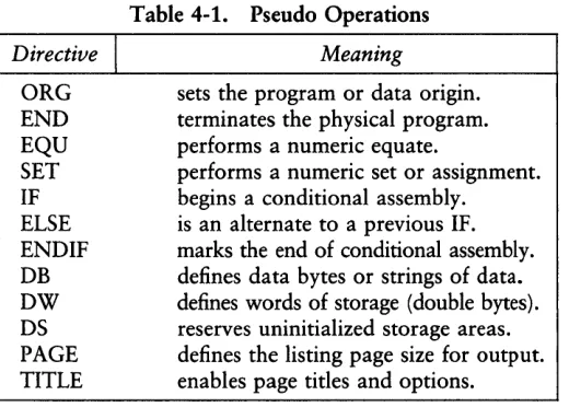
Assembler directives set labels to specific values during assembly, perform condi-tional assembly, define storage areas, and specify starting addresses in the program. Each assembler directive is denoted by a pseudo operation that appears in the oper-ation field of the statement. Table 4-1 lists the acceptable pseudo operoper-ations.
Directive
I
[image:29.468.114.374.210.396.2]ORG END EQU SET IF ELSE ENDIF DB DW DS PAGE TITLE
Table 4-1. Pseudo Operations
Meaning
sets the program or data origin. terminates the physical program. performs a numeric equate.
performs a numeric set or assignment. begins a conditional assembly.
is an alternate to a previous IF. marks the end of conditional assembly. defines data bytes or strings of data. defines words of storage (double bytes). reserves uninitialized storage areas. defines the listing page size for output. enables page titles and options.
In addition to those listed above, several pseudo operations are used in conjunction with the macro processing facilities. MACRO, EXITM, ENDM, REPT, IRPC, IRP, LOCAL, and MACLIB are reserved words. They are fully described in Sections 7 and 8. The nonmacro pseudo operations are detailed below.
4.1 The ORG Directive Programmer's Utilities Guide
4.1 The ORG Directive
The ORG statement takes the form
label ORG expression
where label is an optional program label-an identifier followed by an optional colon (:)-and expression is a 16-bit expression consisting of operands defined before the ORG statement. The assembler begins machine code generation at the location specified in the expression. There can be any number of ORG statements within a program. There are no checks to ensure that you are not redefining overlapping memory areas. Note that most programs written for CP/M begin with an ORG 100H statement that causes machine code generation to begin at the base of the CP/M Transient Program Area. Programs assembled with RMAC and linked with LINK-80 do not need an ORG 100H statement. (See Sections 13 and 15.)
If the ORG statement has a label, then the label takes on the value given by the expression. The expression is the next machine code address to assemble. This label can then be used in the operand field of other statements to represent this expression.
4.2 The END Directive
The END statement is optional in an assembly language program; if present, it must be the last statement. All statements following the END are ignored. The two forms of the END statement are
label END
label END expression
where the label is optional. If the first form is used, the assembly process stops, and the default starting address of the program is taken as 0000. Otherwise, the expres-sion is evaluated and becomes the program starting address. This starting address is included in the last record of the Intel format machine code hex file resulting from the assembly. Most CP/M assembly language programs end with the statement
END 100H
resulting in the default starting address of 100H, the beginning of the Transient Program Area.
Programmer's Utilities Guide 4.3 The EQU Directive
4.3 The EQU Directive
The EQU (equate) statement names synonyms for particular numeric values. The directive takes the form:
label EQU expression
The label must be present, and it must not label any other statement. The assembler evaluates the expression and assigns this value to the identifier given in the label field. The identifier is usually a name describing the value in a more huoriented man-ner. You can use this name throughout the program as a parameter for certain functions. Suppose, for example, that data received from a teletype appears on an input port, and data is sent to the teletype through the next output port in sequence. The series of equate statements that can define these ports for a particular hardware environment is shown below.
TTYBASE
TTYIN
TTYOUT
EQU
EQU
EQU
10H
TTYBASE
TTYBASE+l
;BASE TTY PORT
;TTY DATA IN
;TTY DATA OUT
At a later point in the program, the statements that access the teletype could appear as
IN
OUT
TTYIN
TTY OUT
;READ TTY DATA TO A
;WRITE DATA FROM A
making the program more readable than the absolute I/O port addresses. If the hardware environment is later redefined to start the teletype communications ports at 7FH instead of 10H, the first statement need only be changed to
TTYBASE
EQU
7FH;BASE PORT NUMBER FOR TTY
and the program can be reassembled without changing any other statements.
4.4 The SET Directive Programmer's Utilities Guide
4.4 The SET Directive
The SET statement is similar to the EQU, taking the form
label SET expression
except that the label, taken as a variable name, can occur on other SET statements within the program. The expression is evaluated and becomes the current value associated with the label. Thus, unlike the EQU statement, where a label takes on a single value throughout the program, the SET statement can assign different values to a name at different parts of the program. In particular, the SET statement gives the label a value that is valid from the current SET statement to the point where the label occurs on the next SET statement. The use of SET is similar to the EQU, except that SET is used more often to control conditional assembly within macros.
4.5 The IF, ELSE, and ENDIF Directives
The IF, ELSE, and ENDIF directives define a range of assembly language state-ments to be included or excluded during the assembly process. The IF and ENDIF statements alone can bound a group of statements to be conditionally assembled, as shown in the following example:
IF expression statement#l statement#2
statement#n ENDIF
Upon encountering the IF statement, the assembler evaluates the expression following the IF. All operands in the expression must be defined ahead of the IF statement. If the expression evaluates to a nonzero value, then statement#l through statement#n are assembled. If the expression evaluates to zero, then the statements are listed but not assembled.
Conditional assembly is often used to write a single generic program that includes a number of possible alternative subroutines or program segments, where only a few of the possible alternatives are to be included in any given assembly. Listings 4-1 and 4-2 give an example of such a program.
Programmer's Utilities Guide 4.5 IF, ELSE, and ENDIF
Assume that a console device, either a teletype or a CRT, is connected to an 8080 microcomputer through 110 ports. Due to the electronic environment, the current loop teletype is connected through ports 10H and 11H, while the RS-232 CRT is connected through ports 20H and 21H. The program continually loops, reading and writing console characters. The program shown below operates either with a teletype or a CRT, depending on the value of the symbol TTY.
Listing 4-1 shows an assembly for the teletype environment. Listing 4-2 shows the assembly for a CRT-based system. Note that the assembler leaves the leftmost 16 columns blank when statements are skipped due to a false condition.
CP/M MACRO ASSEM 2.0 #001 Teletype Echo Pro!traM
FFFF TRUE EQU OFFFFH ;OEFINE TRUE
0000 FALSE EQU NOT TRUE ;OEFINE FALSE
FFFF TTY EQU TRUE ;SET TTY ON
0010 TTYBASE EQU 10H ;BASE OF TTY PORTS
0020 CRTBASE EQU 20H ;BASE OF CRT PORTS
IF TTY ;ASSEMBLE TTY PORTS
TITLE 'Teletype Echo Pro!traM'
0010 CONIN EQU TTYBASE ;CONSOLE INPUT
0011 CONOUT EQU TTYBASE+l ;CONSOLE OUT
ENOIF
IF NOT TTY ;ASSEMBLE CRT PORTS TITLE 'CRT Echo Pro!traM'
CONIN EQU CRTBASE ;CONSOLE IN
CONOUT EQU CRTBASE+l ;CONSOLE OUT
ENOIF
0000 OBI0 ECHO: IN CONIN ;REAO CONSOLE
CHARACTER
0002 0311 / OUT CONOUT ; WR ITE CONSOLE
CHARACTER 000l! C30000 JMP ECHO
0007 ENO
Listing 4-1. Conditional Assembly with 1TY True
4.5 IF, ELSE, and ENDIF Programmer's Utilities Guide
CP/M MACRO ASSEM 2.0 #001 CRT Echo Prolfram
FFFF TRUE EQU OFFFFH iOEFINE TRUE
0000 FALSE EQU NOT TRUE iOEFINE FALSE
0000 TTY EQU FALSE iSET CRT ON
0010 TTYBASE EQU 10H iBASE OF TTY PORTS
0020 CRTBASE EQU 20H iBASE OF CRT PORTS
IF TTY iASSEMBLE TTY PORTS
TITLE 'Teletype Echo Prolfram'
CONIN EQU TTYBASE iCONSOLE INPUT
CONOUT EQU TTYBASE+l iCONSOLE OUT
ENOIF
IF NOT TTY iASSEMBLE CRT PORTS TITLE 'CRT Echo Prolfram'
0020 CONIN EQU CRTBASE iCONSOLE IN
0021 CONOUT EQU CRTBASE+l iCONSOLE OUT
ENDIF
0000 OB20 ECHO: IN CONIN iREAD CONSOLE
CHARACTER
0002 0321 OUT CONOUT iWRITE CONSOLE
CHARACTER
0004 C30000 JMP ECHO
0007 END
Listing 4-2. Conditional Assembly with TTY False
Programmer's Utilities Guide 4.5 IF, ELSE, and ENDIF
The ELSE statement can be used as an alternative to an IF statement. The ELSE statement must occur between the IF and ENDIF statements. The form is
IF expression statement#l statement#2
statement#n ELSE
statement#n
+
1 statement#n+
2statement#m ENDIF
If the expression produces a nonzero (true) value, then statements 1 through n are assembled as before. However, the assembly process skips statements n
+
1 through m. When the expression produces a zero value (false), MAC skips statements 1 through n and assembles statements n+
1 through m. For example, the conditional assembly shown in Listings 4-1 and 4-2 can be rewritten as shown in Listing 4-3.CP/M MACRO ASSEM 2.0 #001 CRT Echo Prog'raM
FFFF TRUE EQU OFFFFH iDEF I NE TRUE
0000 FALSE EQU NOT TRUEiOEFINE FALSE
0000 TTY EQU FALSE iSET CRT ON
0010 TTYBASE EQU 10H iBASE OF TTY PORTS
0020 CRTBASE EQU 20H iBASE OF CRT PORTS
IF TTY iASSEMBLE TTY PORTS
TITLE 'Telet)'pe Echo Prog'raM'
CONIN EQU TTYBASE iCONSOLE INPUT
CONOUT EQU TTYBASE+l iCONSOLE OUT
ELSE iASSEMBLE CRT PORTS
TITLE 'CRT Echo Prog'raM'
0020 CONIN EQU CRT BASE iCONSOLE IN
0021 CONOUT EQU CRTBASE+l iCONSOLE OUT
ENOIF
0000 OB20 ECHO: IN CONIN iREAO CONSOLE CHARACTER
0002 0321 OUT CON OUT iWRITE CONSOLE CHARACTER
000l! C30000 JMP ECHO
0007 END
Listing 4-3. Conditional Assembly Using ELSE for Alternate
4.5 IF, ELSE, and ENDIF Programmer's Utilities Guide
Properly balanced IF, ELSE, and END IF statements can be completely contained within the boundaries of outer encompassing conditional assembly groups. The struc-ture outlined below shows properly nested IF, ELSE, and ENDIF statements:
IF exp#l group#l IF exp#2 group#2 ELSE group#3 ENDIF group#4 ELSE group#S IF exp#3 group#6 ENDIF group#7 END IF
Groups 1 through 7 are sequences of statements to be conditionally assembled, and exp#l through exp#3 are expressions that control the conditional assembly. If exp#l is true, then group#l and group#4 are always assembled, and groups 5, 6, and 7 are skipped. Further, if exp#l and exp#2 are both true, then group#2 is also included in the assembly. Otherwise, group#3 is included. If exp#l produces a false value, groups 1, 2, 3, and 4 are skipped, and groups 5 and 7 are always assembled. If exp#3 is true under these circumstances, then group#6 is also included with 5 and 7. Otherwise, it is skipped in the assembly. A structure similar to this is shown in Listing 4-4, where literal true/false values show conditional assembly selection.
4.5 IF, ELSE, and ENDIF Programmer's Utilities Guide
There can be up to eight pending IFs or ELSEs with unresolved ENDIFs at any point in the assembly, but the assembly usually becomes unreadable after two or three levels or nesting. The nesting level restriction also holds, however, for pending IFs and ELSEs during macro evaluation. Nesting level overflow produces an error during assembly.
FFFF 0000
0000 3E05
0002 3EOS
0004 3E08
TRUE FALSE
EQU EQU IF MVI IF MVI ELSE MVI ENDIF MVI ELSE MVI IF MVI ELSE MVI ENDIF MVI ENDIF END
OFFFFH iDEFINE TRUE
NOT TRUE iDEFINE FALSE FALSE
Ad TRUE AI2
A,3
A,a
A,5 TRUE A,S
AI7
A,8
Listing 4-4. Sample Program Using Nested IF, ELSE, and ENDIF
4.6 The DB Directive
The DB directive defines initialized storage areas in single-precision (byte) format.
The statement form is
label DB e#l, e#2, ... , e#n
where the label is optional, and e# 1 through e#n are either expressions that produce 8-bit values (the high-order eight bits are zeros, or the high-order nine bits are ones), or are ASCII strings no longer than 64 characters each. There is no practical restric-tion on the number of expressions included on a single source line. The assembler evaluates expressions and places them into the machine code sequentially following the last program address generated.
4.6 The DB Directive Programmer's Utilities Guide
String characters are similarly placed into memory, starting with the first character and ending with the last character. Strings longer than two characters cannot be used as operands in more complicated expressions. They must stand alone between the commas. Note that ASCII characters are always placed in memory with the high-order (parity) bit reset to zero. Further, recall that there is no translation from lower to upper-case within strings. The optional label can be used to reference the data area throughout the program. The following are examples of valid DB statements:
data:
si9'non:
DB
DB
DB
DB
DB
O,i,2,3,4,5,8
data and Offh,5,377Q,i+2+3+4 'please t)'pe )'our nafTle:' ,cr,if,O 'AB' SHR 8, 'C', 'DE' AND 7FH
HIGH
data, LOW (si9'nonGT
data)4.7 The DW Directive
The DW statement is similar to the DB statement except double-precision (two-byte) words of storage are initialized. The form of the DW statement is
label DW e#l, e#2, ... , e#n
where the label is optional, and e#l through e#n are expressions that produce 16-bit values. Note that ASCII strings one or two characters long are allowed, but strings longer that two characters are disallowed. In all cases, the data storage is consistent with the 8080 processor; the least significant byte of the expression is stored first in memory, followed by the most significant byte. The following are examples of properly formed DW statements:
doub:
DW
DW
Offefh, doub+4, si9'non-$,255+255 ' a ' , 5, 'AB', 'CD', doub LT si9'non
Programmer's Utilities Guide 4.8 The DS Directive
4.8 The DS Directive
The DS statement reserves an area of uninitialized memory and takes the form
label DS expression
where the label is optional. The assembler begins subsequent code generation after the area reserved by the DS. Thus, the DS statement given above has exactly the same effect as the statement sequences:
label: EQU $
ORG $
+
expression;CURRENT CODE LOC ;MOVE PAST AREA
4.9 The PAGE and TITLE Directives
The PAGE and TITLE pseudo operations give you control over the output format-ting that is sent to the PRN file or directly to the printer device. The forms for the P AGE statement are
PAGE
PAGE expression
If the PAGE statement stands alone, an ASCII CTRL-L (form-feed) is sent to the output file after the PAGE statement has been printed. The PAGE command is often issued directly ahead of major sections of an assembly language program, such as a group of subroutines, to cause the next statement to appear at the top of the follow-ing page.
The second form of the PAGE command specifies the output page size. In this case, the expression following the PAGE pseudo operation determines the number of out-put lines to be printed on each page. If the expression is zero, there are no page breaks. The print file is simply a continuous sequence of annotated output lines. If the expression is nonzero, then the page size is set to the value of the expression. Form-feeds are issued to cause page ejects when this count is reached for each page.
4.9 PAGE and TITLE Directives Programmer's Utilities Guide
The assembler initially assumes that
PAGE 58
is in effect, producing a page eject at the beginning of the listing and at each 56-line increment.
The TITLE directive takes the form
TITLE string-constant
where the string-constant is an ASCII string enclosed in apostrophes, not exceeding 64 characters in length. If a TITLE pseudo operation is given during the assembly, each page of the listing file is prefixed with the title line, preceded by a standard MAC header. The title line thus appears as
CP/M MACRO ASSEM n.n #ppp string-constant
where n.n is the MAC version number, #ppp is the page number in the listing, and string-constant is the string given in the TITLE pseudo operation. MAC initially assumes that the TITLE operation is not in effect. When specified, the title line and the blank line following the title are not included in the line count for the page. No more than one TITLE statement is included in a program. Similarly, only one PAGE statement with the expression option is included.
If a TITLE statement is included, and the Symbol Table is being appended to the PRN file (see Section 10), then the SYM file also cont'i\ins the title at the beginning of the symbol listing with page breaks given by either the default or specified value of the PAGE statement.
Programmer's Utilities Guide 4.10 A Sample Program
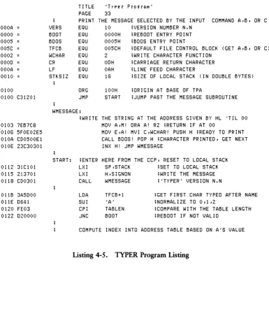
4.10 A Sample Program Using Pseudo Operations
The program in Listing 4-5 demonstrates the pseudo operations available in MAC. The sample program, called TYPER, operates in the CP/M environment by selecting one of three messages for output at the console. This program is created using the ED program, assembled using MAC, and then placed into COM file format using the CP/M LOAD function. After these steps have been accomplished, TYPER exe-cutes at the Console Command Processor level of CP/M by typing one of the commands:
TYPER A TYPER B TYPER C
to select message A, B, or C for printing. The TYPER program loads under the CCP and jumps to the label START where the 8080 stack is initialized. The TYPER program then prints its sign-on message:
'typer' version 1.0
The program then retrieves the first character typed at the console following the command TYPER. This character should be A, B, or C. If one of these letters is not specified, then TYPER reboots the CP/M system to give control back to the CCP. If a valid letter is provided, TYPER selects one of the three messages (MESS@A, MESS@B, or MESS@C) and prints it at the console before returning to CP/M.
The TITLE and PAGE statements produce a title at the beginning of each page; page size is 33 lines, excluding the title lines. Form-feeds are suppressed. A number of EQU statements at the beginning improve program readability. Note that through-out the program the exclamation point allows several simple assembly language statements on the same line. Although multiple statements make the program more compact, they often decrease the overall readability of the source program. Note also that the program terminates without the END statement. The END statement is necessary only if a starting address is specified. The END statement is often included, however, to maintain compatibility with other assemblers.
The DB statements labeled by SIGNON contain simple strings of characters and expressions that produce single-byte values. The DW statement following TABLE defines the base address of each string, corresponding to A, B, and C. Finally, the DS statement at the end of the program reserves space for the stack defined within the TYPER program.
4.10 A Sample Program Programmer's Utilities Guide OOOA 0000 0005 005C 0002 OOOD OOOA 0010 0100 0100 0103 0106 010A 010E 0112 0115 0118 o liB 011E 0120 0122
CP/M MACRO ASSEM 2.0 1001 Typer Pro~ram
C31201 7EB7C8 5FOE02E5 CD0500El 23C30301 31CI0l 213701 CD0301 3A5DOO D641 FE03 D20000
TITLE 'Typer Program'
PAGE 33
PRINT THE MESSAGE SELECTED BY THE INPUT COMMAND A,B, OR C
VERS EQU 10 ;VERSIoN NUMBER N.N
BOOT EQU
BDoS EQU
TFCB EQU
WCHAR EQU
CR EQU
LF EQU
STKSIZ EQU
oRG JMP WMESSAGE: OOOOH 0005H 005CH 2 ODH OAH 16 100H START
;REBooT ENTRY POINT ;BDoS ENTRY POINT
;DEFAULT FILE CONTROL BLOCK (GET A,B, OR C) ;WRITE CHARACTER FUNCTION
;CARRIAGE RETURN CHARACTER ;LINE FEED CHARACTER
;SIZE OF LOCAL STACK (IN DOUBLE BYTES)
;oRIGIN AT BASE OF TPA
;JUMP PAST THE MESSAGE SUBROUTINE
;WRITE THE STRING AT THE ADDRESS GIVEN BY HL 'TIL 00 MoV A,M! ORA A! RZ ;RETURN IF AT 00
MoV E,A! MVI C,WCHAR! PUSH H ;READY TO PRINT CALL BDoS! POP H jCHARACTER PRINTED, GET NEXT
INX H! JMP WMESSAGE
START: jENTER HERE FROM THE CCP, RESET TO LOCAL STACK
LXI SP,STACK ;SET TO LOCAL STACK
LXI H,SIGNoN jWRITE THE MESSAGE
CALL WMESSAGE j'TYPER' VERSION N.N
[image:42.469.32.417.81.523.2]LDA SUI CPI JNC TFCB+l 'A' TABLEN BOOT
;GET FIRST CHAR TYPED AFTER NAME iNoRMALIZE TO 0,1,2
;CoMPARE WITH THE TABLE LENGTH iREBooT IF NOT VALID
COMPUTE INDEX INTO ADDRESS TABLE BASED ON A'S VALUE
Listing 4-5. TYPER Program Listing
Programmer's Utilities Guide 4.10 A Sample Program
CP/M MACRO ASSEM 2.0 #002 Typer Pro~raM
0125 5F MmJ E,A jLOW ORDER INDEX
0126 1600 M~JI 0,0 jEXTENDED TO DOUBLE PRECISION
0128 214001 LXI H,TABLE jBASE OF THE TABLE TO INDEX
012B 19 DAD 0 jSINGLE PRECISION INDEX
012C 19 DAD 0 jDOUBLE PRECISION INDEX
0120 5E MmJ E,M jLOW ORDER BYTE TO E
012E 23 INX H
012F 56 MOV D,M jHIGH ORDER MESSAGE ADDRESS TO DE
0130 EB XCHG jREADY FOR PRINTOUT
0131 CD0301 CALL WMESSAGE jMESSAGE WRITTEN TO CONSOLE
0134 C30000 JMP BOOT jREBOOT, GO BACK TO CCP LEVEL
0137 2774797065 0147 312E30 014A ODOAOO
SIGNON: DATA
DB DB DB
AREAS
"'typer" version
l,JERS/l0+'O', '.', lJERS MOD 10 +'0' CR,LF,O jEND OF MESSAGE
TABLE: jOF MESSAGE BASE ADDRESSES
0140 5301670182 OW MESS@A,MESS@B,MESS@C
0003 TABLEN EQU ($-TABLEI/2 jLENGTH OF TABLE
0153 7468697320MESS@A: DB 0167 796F752073MESS@B: DB 0182 7468697320MESS@C: DB
01Al DS
STACK:
'this is rllessa~e a',CR,LF,O 'YOU selected b this tiMe' ,CR,LF,O 'this Messa~e COMes out for c',CR,LF,O
STKSIZ*2 jRESERVES AREA FOR STACK
Listing 4-5. (continued)
End of Section 4
Section 5
Operation Codes
Operation codes, found in the operation field of the statement, form the principal components of assembly language programs. MAC accepts all the standard mnemon-ics for the Intel 8080 microcomputer. These standard mnemonmnemon-ics are detailed in the
8080 Assembly Language Programming Manual, published by Intel. Labels are optional on each input line and, if included, take the value of the instruction address immedi-ately before the instruction is issued by the assembler. The individual operators are listed briefly in the following sections. See the Intel documentation for exact operator details. In this section, operation codes are categorized for discussion; a sample assembly shows the hexadecimal codes produced for each operation. The following notation is used throughout:
e3 represents a 3-bit value in the range 0-7 that usually takes one of the predefined register values A, B, C, D, H, L, M, SP, or PSW
e8 represents an 8-bit value in the range 0-255; signed 8-bit values are also allowed in the range -128 through
+
127e16 represents a 16-bit value in the range 0-65535
where eJ, e8, and e16 can be formed from an arbitrary combination of operands and operators in a well-formed expression. In some cases, the operands are restricted to particular values within the range, such as the PUSH instruction.
5.1 Jumps, Calls, and Returns Programmer's Utilities Guide
5.1 Jumps, Calls, and Returns
In some cases, the condition flags are tested to determine whether or not to take the jump, call, or return. The forms are shown below. The jump instructions are
JMP e16 JNC e16 JPE e16
JNZ e16 JC e16 JP e16
The call instructions are
CALL e16 CNC e16 CPE e16
CNZ e16 CC e16 CP e16
The return instructions are
RET RNC RPE
RNZ RC RP
The restart instruction takes the form:
RSTe3
JZ e16 JPO e16 JM e16
CZ e16 CPO e16 CM e16
RZ RPO RM
and performs exactly the same function as the instruction CALL e3
*
8 except that RST e3 requires only one byte of memory.Listing 5-1 shows the hexadecimal codes for each instruction, along with a short comment on each line describing the function of the instruction.
Programmer's Utilities Guide 5.1 Jumps, Calls, and Returns
CP/M MACRO ASSEM 2.0 #001 8080 JUMPS, CALLS, AND RETURNS
0000 C31BOO 0003 C25COO 0006 CAOOOI 0008 D21FOO OOOC DA4142 OOOF E21700 0012 EAODOO 0015 F24100 0018 FA1BOO
001B CD3600 001E C43800 0021 CCOOOI 0024 D43AOO 0027 DCOOOO 002A E43200 0020 EC0800 0030 F44100 0033 FC4100
0036 C7 0037 OF
0038 CS 0038 CO 003A C8 003B DO 003C 08 0030 EO 003E E8 003F FO 0040 F8
0002
0041
L1:
S 1 :
X
GAMMA:
TITLE '8080 JUMPS, CALLS, AND RETURNS'
JUMPS ALL REQUIRE A 16-BIT OPERAND
JMP Ll jJUMP UNCONDITIONALLY TO LABEL JNZ Ll+'A' jJUMP ON NON ZERO TO LABEL JZ 100H jJUMP ON ZERO CONDITION TO LABEL JNC Ll+4 jJUMP ON NO CARRY TO LABEL JC 'AB' jJUMP ON CARRY TO LABEL JPO $+8 jJUMP ON PARITY ODD TO LABEL JPE Ll/2 jJUMP ON EVEN PARITY TO LABEL JP
JM
GAMMA jJUMP ON POSITIVE RESULT TO LABEL LOW L1 jJUMP ON MINUS TO LABEL
CALL OPERATIONS ALL REQUIRE A 16-BIT OPERAND CALL CNZ CZ CNC CC CPO CPE CP CM
Sl jCALL SUBROUTINE UNCONDITIONALLY Sl+X jCALL SUBROUTINE IF NON ZERO FLAG 100H jCALL SUBROUTINE IF ZERO FLAG Sl+4 jCALL SUBROUTINE IF NO CARRY FLAG Sl MOD 3jCALL SUBROUTINE IF CARRY FLAG $+8 jCALL SUBROUTINE IF PARITY ODD Sl-$ jCALL SUBROUTINE IF PARITY EVEN GAMMA jCALL SUBROUTINE IF POSITIVE GAM$MA jCALL SUBROUTINE IF MINUS FLAG
PROGRAMMED RESTART (RST) REQUIRES 3-BIT OPERAND (RST X IS EQUIVALENT TO CALL X*8)
RST 0 jRESTART TO LOCATION 0
RST X+l
RETURN INSTRUCTIONS HAVE NO OPERAND RET RNZ RZ RNC RC RPO RPE RP RM EQU END 2
jRETURN FROM SUBROUTINE jRETURN IF NON ZERO jRETURN IF ZERO FLAG SET jRETURN IF NO CARRY FLAG jRETURN IF CARRY FLAG SET jRETURN IF PARITY IS ODD jRETURN IF PARITY IS EVEN jRETURN IF POSITIVE RESULT jRETURN IF MINUS FLAG SET
Listing 5-1. Assembly Showing Jumps, Calls, Returns, and Restarts