International Journal of Emerging Technology and Advanced Engineering
Website: www.ijetae.com (ISSN 2250-2459,ISO 9001:2008 Certified Journal, Volume 3, Issue 6, June 2013)
406
Design and Analysis of a Leaf Spring for automobile
suspension system: A Review
Baviskar A. C.
1, Bhamre V. G.
2, Sarode S. S.
31M.E. Student, 2,3Associate Prof., Mechanical Engg. Dept., S.N.D.COE & R.C. Yeola, Dist.-Nasik, India
Abstract -The aim of this review paper is to represent a general study on the design, analysis of leaf spring. The suspension system in a vehicle significantly affects the behavior of vehicle, i.e. vibration characteristics including ride comfort, stability etc. Leaf springs are commonly used in the vehicle suspension system and are subjected to millions of varying stress cycles leading to fatigue failure. A lot of research has been done for improving the performance of leaf spring. Now the automobile industry has shown interest in the replacement of steel spring with composite leaf spring. In general, it is found that fiberglass material has better strength characteristic and lighter in weight as compare to steel for leaf spring. In this paper ther e is reviewed some papers on t h e design and analysis leaf spring performance and fatigue life prediction of leaf spring. There is also the analysis of failure in leaf spring. Also the analysis of leaf spring with ansys is done. The automakers can reduce product development cost and time while improving the safety, comfort, and durability of the vehicles they produce. The predictive capability of CAE tools has progressed to the point where much of the design verification is now done using computer simulation rather than physical prototype testing.
Keywords - Leaf spring, finite element analysis, FEM, CAE tool.
I. INTRODUCTION
In order to conserve natural resources and economize energy, weight reduction has been the main focus of automobile manufacturer in the present scenario. Weight reduction can be achieved primarily by the introduction of better material, design optimization and better manufacturing processes. The suspension leaf spring is one of the potential items for weight reduction in automobile as it accounts for ten to twenty percent of the unstrung weight. This helps in achieving the vehicle with improved riding qualities. It is well known that springs, are designed to absorb and store energy and then release it. Hence, the strain energy of the material becomes a major factor in designing the springs. The introduction of composite materials was made it possible to reduce the weight of the leaf spring without any reduction on load carrying capacity and stiffness. Since; the composite materials have more elastic strain energy storage capacity and high strength-to-weight ratio as compared to those of steel.
Several papers were devoted to the application of composite materials for automobiles I. Rajendran studied the application of composite structures for automobiles and design optimization of a composite leaf spring. Great effort has been made by the automotive Multi leaf springs used in automotive vehicles normally consists of full length leaves and graduated length leaves. The specimen under this research work consists of nine leaves, two eye pins, centre bolt with nut etc CAE tools are being used to analyze the robustness and performance of components and assemblies. It uses a numerical technique called the finite element method (FEM). Using FEA Multi leaf spring is modeled using the discrete building blocks called elements. Each element has some equations that describe how it responds to certain loads. The sum of the response of all the elements in the model gives the total response of the design. CAE depends upon actual assumptions of the assembly which acts as input data. CAE has become an important technology with benefits such as lower costs and a shortened design cycle.
II. LITERATURE REVIEW
I. Rajendran , S.Vijayarangan has presented an artificial genetics approach for the design optimization of composite leaf spring. The design variable (thickness and width) of steel and composite leaf springs are optimized by making use of GA (Genetic Algorithm). Optimization using GA has contributed to a reduction of 8% of the steel spring weight and 23.4% of the composite spring weight.
H.A. Al Qureshi has described a single leaf, variable thickness spring of glass fiver reinforced plastic (GFRP) with similar mechanical and geometrical properties to the multi-leaf steel spring was designed, fabricated and tested.
International Journal of Emerging Technology and Advanced Engineering
Website: www.ijetae.com (ISSN 2250-2459,ISO 9001:2008 Certified Journal, Volume 3, Issue 6, June 2013)
407
W. Hufenbach & F. Adam has presented a method to adjust the spring r a t e of an leaf spring element. For dimensioning of this system a strategy was developed and validated. The tests of manufactured leaf spring elements with different reinforcements show a good agreement between the calculation and the measured characteristic.
B.Vijaya Lakshmi has presented the static analysis on 8-leafs we can concluded that E-glass epoxy is better than using Mild-steel as though stresses are little bit higher than mild steel, E-glass epoxy is having good
yield strength value (5e+008N/m2) and also epoxy material components are easy to manufacture and this having very low weight.
III. LAMINATED SEMI-ELLIPTIC SPRING
[image:2.595.344.526.468.585.2]A laminated semi-elliptic spring .The top leaf is known as the master leaf. The eye is provided for attaching the spring with another machine member. The amount of bend that is given to the spring from the central line, passing through the eyes, is known as camber. The camber is provided so that even at the maximum load the deflected spring should not touch the machine member to which it is attached. The camber shown in the figure is known as positive camber. The central clamp is required to hold the leaves of the spring. However, the bolt holes required to engage the bolts to clamp the leaves weaken the spring to some extent. Rebound clips help to share the load from the master leaf to the graduated leaf.
Fig 3.1 Laminated semi-elliptic leaf spring
The leaf spring involves two full length leaves and seven graduated leaves, four packing which are made of 65Si7 material. This conventional leaf spring model consists of 37 parts which, includes two full length leave, seven graduated leaves. The remaining part involves four rebound clips of MS, four shim pipes of C.D.S.T/ERW, centre nut & bolt and bush of bronze. The experimental setup consists of a full scale testing machine for leaf spring, jigs and fixture.
The system consists of a hydraulic power pack to give a hydraulic pressure of 20.6 M Pa with a flow rate of 210l pm, which is sent to a hydraulic actuator to operate at a frequency of 0.3 Hz with the displacement specified by the alternating load. This involves applying the axial load on the leaf spring and measure the deflection and bending stress. Supavut,Chantranuwathana have simulated a leaf spring model. An experimental leaf spring model was verified by using a leaf spring test rig The master leaf of a laminated spring is hinged to the supports. The support forces induce, stresses due to longitudinal forces and stresses arising due to possible twist. Hence, the master leaf is more stressed compared to other the graduated leaves. Methods to reduce additional stresses could be,
1. Master leaf is made of stronger material than the other leaves.
2. Master leaf is made thinner than the other leaves. This will reduce the bending stress as evident from stress equation.
3. Another common practice is to increase the radius of curvature of the master leaf than the next leaf that can measure vertical static deflection of leaf spring under static loading condition.
[image:2.595.57.275.497.628.2]A. Stresses due to support hinges
Fig 3.2 Nipping of leaf spring
International Journal of Emerging Technology and Advanced Engineering
Website: www.ijetae.com (ISSN 2250-2459,ISO 9001:2008 Certified Journal, Volume 3, Issue 6, June 2013)
408
However, by such operation of tightening the central bolt, the additional leaf that is placed beneath the master leaf has a tendency to flatten out and as a result the stress pattern of the additional leaf will be reverse of that of the master leaf, tensile stress is produced at the inner curvature and compressive stress is produced at the outer curvature. Hence, when the spring is loaded, for both the master leaf and the additional leaf, tensile stress will be produced at the inner curvature and compressive stress will be produced at the outer curvature. Therefore, due to opposite nature of initial stress and loading stress, the master leaf will experience lesser stress on both the surfaces. However, due to same nature of initial stress and loading stress, the additional leaf is stressed more compared to the master leaf. But, it is to be noted that the higher stress on the additional leaf is actually shared between all other leaves than the master leaf. This practice of stress relief in the master leaf is known as “Nipping of leaf spring”. As a matter of fact, all the leaves of a laminated leaf spring do have certain amount of nipping, so that there will be gaps between the leaves, as a result the stresses will be uniformly distributed and accumulated dusts can also be cleaned.IV. LEAF SPRING FAILURE
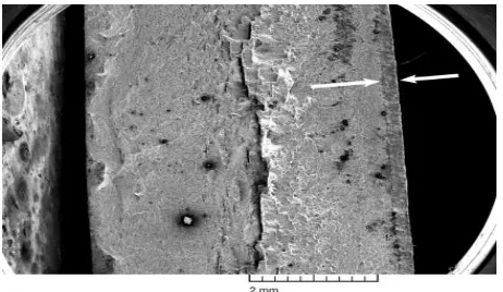
The determination of the point of failure during an accident sequence of a rear leaf spring in a sport utility vehicle is presented in terms of fracture surface analysis and residual-strength estimates. Marks at the scene of the accident pointed to two possibilities for the point of failure: marks in the roadway at the start of the accident sequence and a rock strike near the end of the sequence. Evidence from rust and chemical contamination on the fracture pointed to the spring having been cracked in half prior to the accident. Extensive woody fracture and secondary cracking at the mid-plane of the spring was evidence for segregation and weakness in the spring. Stress estimates for the effect of both the weakness and prior cracking on the residual strength of the spring revealed reductions in strength of the spring that could produce fracture at the start of the accident sequence. The point of failure of the spring was placed at the start of the accident sequence. A scanning electron microscope (SEM) was used to examine the fracture on the eye at higher magni-fications. Examination of the mid-plane fracture was difficult because the mid-plane fracture surface faced the surface of the spring itself. Such a geometry creates signal detection problems, particularly for X-ray analysis. However, significant results were achieved by repeated repositioning of the spring eye.
[image:3.595.318.549.577.711.2]This old crack exhibited features indicative of a corroded surface, as can be seen fracture between the old crack and the mid-plane was also rusted but less so than the old crack. The fracture mode in the old crack was difficult to see because of corrosion and physical damage. However, a few small areas were clear enough to reveal uniform, very small micro voids. Fracture between the old crack and the mid-plane was also by micro void coalescence, but the void size was duplex with large and small micro voids. The fracture was also rougher. X-ray spectroscopy of the old crack in the SEM revealed unusually high peaks for oxygen, silicon, calcium, chlorine, sulfur, and aluminum, the X-ray spectra from the old crack. Calcium, silicon, and aluminum are contamination elements, because they should not be present at the observed concentrations on a 5160 steel fracture surface. The geological report revealed calcium carbonate, alumina, and, to a lesser extent, silica were a major portion of the road material. Chlorine was not reported in the roadbed analysis, and roads are not salted for ice where the vehicle was driven. obvious source for chlorine in this case was the known transport of the vehicle by an ocean-going ship. The high oxygen level is consistent with corrosion. The source of the sulfur is not known at this time, area of “thumbnail-shaped” crack origins on the inside diameter (ID) surface. Woody fracture regions on this specimen were observed to be areas of decohesion of flat, elongated sulfide inclusions with regions of very fine micro voids in the broken ligaments. Bands of intergranular fracture were observed to be mixed in with the fracture, both of these morphologies together. X-ray analysis of the intergranular fracture area and the woody area strong peaks for carbon, oxygen, silicon, aluminum, and chlorine. For comparison, X-ray analysis of the clean, inboard half of the fracture revealed only a small peak for silicon in addition to the normal peaks for iron, manganese, and chromium.
International Journal of Emerging Technology and Advanced Engineering
Website: www.ijetae.com (ISSN 2250-2459,ISO 9001:2008 Certified Journal, Volume 3, Issue 6, June 2013)
409
V. STRESS ANALYSISStress calculations were performed to estimate the reduction in strength in the spring resulting from cracks existing before the accident and the mid-plane segregation. Exemplar spring test data were also used to provide a basis for estimating the reduction in strength. The reduction-in-strength estimates were then used to determine if normally expected dirt road forces in the absence of a large rock strike were adequate to rupture this spring. Finite-element stress analysis was used to study the existence of transverse tensile stresses at the location of the fracture. The leaf spring was secured directly to the vehicle frame at the forward end and through a shackle assembly at the end.
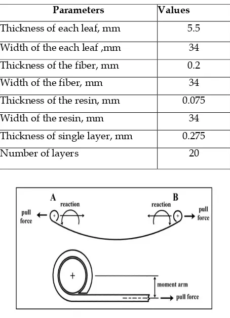
Fig 5.1 Reaction forces on the spring eyes in the vehicle
These crack depth measurements for the old OD crack, produced an estimate of 1460 MPa for an outer fiber bending stress required for spring fracture. The calculated outer fiber (or outer surface) bending stress estimated for fracture in the presence of the small OD crack is at or below the expected tensile strength for the spring. This analysis indicates that the strength has been reduced when compared to the nominal properties. Any delimitation in the spring would raise the stresses and result in unstable fracture at even lower force levels. (The observed elimination would double the stresses.). The longitudinal force required to produce the fracture initiation stress predicted by fracture mechanics was estimated by elastic bending calculations. The force to reach 146 M Pa was estimated to be 23,000 N for no delimitation and 10,200 N for the observed elimination in the accident spring. Using 48,200 N pull to failure from test results on exemplar springs yielded a 52 to 79% reduction in spring strength. These numbers demonstrate the serious reduction in strength possible for both the small crack and the delimitation. Evidence of the outer half being cracked for some time indicates that the reduction in strength did in fact occur. plane-strain unstable rupture occurred.
The toughness of the ID half of the spring was less than that of the OD half because of the extensive presence of intergranular fracture, which is evidence for embrittlement. Therefore, the combination of a stable tear and dynamic loading probably further reduced the final longitudinal rupture force below 0.72 g. criterion.
The mid-plane segregation leading to delaminating would be expected to arrest the running crack from the outsidesurface, and it did. This would leave the spring weakened but intact rubbing at the mid-plane demonstrates that this arrest did occur. Residual strength for this condition was estimated by assuming the spring was cracked halfway through.
[image:4.595.320.547.305.618.2]TABLE I
Fig 5.2 Reaction forces in spring eye in the pull test test
A 12,900 N pull to rupture was estimated using this approach. This is a 73% reduction in strength over the exemplar springs, or 0.72 g forward deceleration for a 17,800 N vehicle. Accelerations of 0.72 g or less are in the range of reasonably expected forces for a vehicle traveling on dirt or unimproved roads. Final rupture forces for the spring were probably lower still.
Parameters Values
Thicknessofeachleaf,mm 5.5
Widthoftheeachleaf,mm 34
Thicknessofthefiber,mm 0.2
Widthofthefiber,mm 34
Thicknessoftheresin,mm 0.075
Widthoftheresin,mm 34
Thicknessofsinglelayer,mm 0.275
International Journal of Emerging Technology and Advanced Engineering
Website: www.ijetae.com (ISSN 2250-2459,ISO 9001:2008 Certified Journal, Volume 3, Issue 6, June 2013)
410
Thumbnail regions were observed at the ID surface on the accident aexemplar springs at approximately 45° to the spring surface and to the rest of the ID half of the fracture. These thumbnail regions are at least plane-stress stable tear features.VI. FINITE ELEMENT ANALYSIS OF COMPOSITE LEAF SPRING
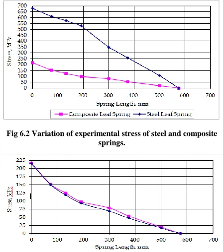
[image:5.595.54.276.354.474.2]With the extensive use of laminated composite materials in almost all engineering fields, the optimal design of laminated composites has been an extensive subject of research in recent years. The dimensions of the composite leaf spring are taken as that of the conventional steel leaf spring. Each leaf of the composite leaf spring consists of 20 plies of thickness 0.275 mm each. The number of leaves is also the same for composite leaf spring. The following graphs show the analysis of spring.
[image:5.595.52.276.355.609.2]Fig 6.2 Variation of experimental stress of steel and composite springs.
Fig 6.3 Variation of longitudinal stress of composite leaf spring.
VII. CONCLUSION
The composite leaf spring is lighter than conventional steel leaf spring with similar design specifications but not always is cost- effective over their steel counterparts. Composite materials have more elastic strain energy storage capacity and high strength to weight ratio as compared with those of steel. Therefore, it is concluded that composite leaf spring is an effective replacement for the existing steel leaf spring in automobile.
E-glass epoxy is better than using Mild-steel as though stresses are little bit higher than mild steel, E-glass epoxy is having good yield strength value. The prior cracking in the spring was extensive
enough to reduce the strength of the spring to the point where normal dirt road forces were adequate to produce rupture.
The weight of the leaf spring is reduced considerably about 85 % by replacing steel leaf spring with composite leaf spring. Thus, the objective of reducing the unstrung mass.
REFERENCES
[1] I. Rajendran, S. Vijayarangan “Optimal Design of a Composite Leaf Spring Using the Genetic Algorithms”Computer and Structures 79 (2001) 1121-1129
[2] H. A. Al-Qureshi “Automobile leaf springs from composite materials” Journal of Material Processing Technology, vol-118, p. p 58 – 61. (2001)
[3] M.L Aggarwal, V.P. Agrawal, R.A.Khan “A stress approach model for predictions of fatigue life by shot peening of EN45A spring steel” International Journal of Fatigue 28 (2006) 1845– 1853
[4] M Senthil Kumar And Vijayarangan “Static analysis and fatigue life prediction of steel and composite leaf spring for light passenger vehicles” Journal of scientific and Industries Research Vol. 66, February 2007 pp 128-134
[5] M Senthil Kumar, S Vijayarangan “Analytical and Experimental Studies on Fatigue Life Prediction of Steel and Composite Multi-leaf Spring for Light Passenger Vehicles Using Life Data Analysis” Journal- ISSN 1392-1320 MATERIALS SCIENCE (MEDZIAGOTYRA) Vol.13, No. 2.2007
[6] F.N. Ahmad Refngah, S. Abdullah and A Jalar, L.B. Chua “Life Assessment of a parabolic Spring Under Cyclic Strain Loading” European Journal of Scientific Research ISSN 1450-216X [7] S. Abdullah, C.K.E. Niz Wan and M.Z. Nuaw “A Study of
Fatigue Data Editing using the Short-Time Fourier Transform(STFT)” Journal-American Journal of applied Sciences 6(4):565-575,2009 ISSN 1546-9239
[8] Gulur Siddaramanna Shiva Shankar, Sambagam Vijayarangan “Mo no Composite Leaf Spring for Light Weight Vehicle –1979 [9] M. M. Patunkar1, D. R. Dolas2 “Modeling and Analysis of
Composite Leaf Spring under the Static Load Condition by using FEA” International Journal of Mechanical & Industrial Engineering, Volume 1 Issue 1-2011
[10] K. K. Jadhao, Dr. R.S Dalu- “Experimental Investigation & Numerical Analysis of leaf spring “International Journal of Mechanical & Industrial Engineering, Volume 2 Issue 1-2007 [11] Vinkel Arora et al “A Comparative Study on CAE and
Experimental Results of Leaf Springs in Automotive Vehicle” ISSN: 0975-5462 Vol. 3 No. 9 Sept. 2011 (IJEST)
[12] Dakshraj Kothari, Rajesh Satankar “Review of Researches on Leaf Spring Regarding Use of Composite Material and Various methods for Predicting Fatigue Life” IJCRR Vol. 4 issue 01 Jan. 2012.