Analysis of a Complex Architectural Style C2
Using Modeling Language Alloy
Ashish Kumar Dwivedi
∗,
Santanu Kumar Rath
Department of Computer Science and Engineering, National Institute of Technology, Rourkela, 769008, Odisha, India
∗Corresponding Author: [email protected]
Copyright c⃝2014 Horizon Research Publishing All rights reserved.
Abstract
Software architecture plays an important role in the high level design of a system in terms of components, connectors, and configuration. The main building block of software architecture is an architectural style that provides domain specific design semantics. Although many architectural descrip-tion languages (ADLs) are available in literature for modeling notations to support architecture based development, these ADLs lack proper tool support in terms of formal modeling and visualization. Hence formal methods are used for modeling and verification of architectural styles. In this study, an attempt has been made to formalize one complex style i.e., C2 ( component and connector) using formal specification language Alloy. For consistency checking of modeling notations, the model checker Alloy Analyzer is used. It automatically checks properties such as compatibility between components and connectors, satisfiability of predicates over the architectural structure, and consistency of a style. For modeling and verification of C2 architectural style, one case study on cruise control system has been considered. At the end of this study performance evaluation among different SAT solvers associated with Alloy Analyzer has been performed in order to assess the quality.Keywords
Software Architecture, Architectural style, C2 style, Alloy, Alloy Analyzer, Cruise Control System1
Introduction
A software architecture comprises a set of principal design decisions that deals with high-level structure of a system [1]. In the architectural development process, design decisions are usually being represented in terms of structure, behavior, interaction, and non-functional properties of the system. In the present day of soft-ware development, the complexity of desired outcomes are increases day by day. The present day, software development activities are shifting the emphasis from lines of code to architectural elements i.e., software com-ponents and connectors. Software architect intends to build systems across multiple application domains. He feels that under given conditions, some design decisions occur in solution. An architectural style is an architec-tural design decisions to capture knowledge of effective designs for achieving specified goals in a given devel-opment context [2]. Styles provide a common seman-tics for a software architect in order to make the design more easily understandable. Many styles are available, such as client-server, virtual machine, pipe-and-filter, blackboard, rule-based, publish-subscriber, event-based, peer-to-peer etc. for the development of a system. As the complexity of the system increases, large number of complex styles have been introduced such as C2 (com-ponents and connectors), CORBA, REST architecture etc.
ar-chitecture [3]. These ADLs support mathematical nota-tions and tools for modeling different architectural styles and architectural patterns. The use of ADLs vary from one problem to another e.g., Rapide [4] is used to model component interface and external behavior of a system, whereas Wright [5] models an architectural element con-nector. These ADLs have limitations for tool support in terms of modeling, platform support and formal verifi-cation. A number of complex styles have also been in-troduced for modeling and visualization of complex and heterogeneous systems. The ADLs are not sufficient for modeling and analyzing of complex styles. Because, the complex styles provide a semi-formal notation for the analysis of a complex system. Hence formal methods are being considered for modeling, refinement, and for-mal verification of software architecture. Forfor-mal meth-ods and model checking tools are helpful to support ar-chitecture based development.
Formal methods are collection of tools and techniques that can capture the abstract features of a system [6]. Formal specification is used to describe the software re-quirements precisely and unambiguously. In order to check whether the modeled system complies with the user requirements, it needs to verify and validate the model. A number of analysis techniques such as, reach-ability analysis, static code analysis, automated theo-rem proving, model checking etc. are available for test-ing and evaluattest-ing non-functional properties based on the architectural styles. Among them, model checking is a verification technique, used to verify whether an architectural model conforms to expected requirements. Model checking of any software system is the algorithmic analysis of programs to prove properties of their execu-tions. By model checking, important system properties like functional behavior, consistency of internal struc-ture, and performance characteristics are verified. Logic and theorem proving provide the conceptual framework in which the goal is to formalize the fundamental re-quirements and specify algorithmic procedures for the analysis of requirements [7].
The goal of this study is to analyze C2 style [1] using formal modeling language Alloy [8]. A safety critical sys-tem i.e., cruise control syssys-tem (CCS) [9] has been consid-ered as a case study for designing the architecture in C2 style. Subsequently Alloy notations of C2 style are ana-lyzed using the model generator Alloy Analyzer [10]. A number of formal models have been proposed for simple styles such as, client-server, publish-subscriber, pipe and filter, event-based etc. It is observed that more rigorous study needs to be carried out for formalization of com-plex styles such as, C2. ACME [11] is an architectural in-terchange language used to model a system using differ-ent simple architectural styles such as call-return,
data-flow, event-based, and repository. It supports mapping of architectural specifications from one ADL to another; but ACME can not modeled system in C2 style. Gener-ally C2SADEL (Software Architecture Description and Evolution Language for style) is used to modeled C2-style. The tool known as DRADEL (Development of Robust Architectures using a Description and Evolution Language) [12] supported by C2SADEL provides tex-tual and graphical modeling as well as skeleton genera-tion; but this tool is not sufficient for simulation and for-mal verification. Presently systems are running in a dis-tributed, heterogeneous environment and software com-ponents of a system are written in different languages. Hence, the software components should follow the prin-ciple of substrate independence. The C2-style provides a large number of benefits such as, substrate indepen-dence, accommodating heterogeneity, support for prod-uct lines [13], ability to design in model-view-controller pattern, support for distributed applications [14, 15].
2
Preliminaries
2.1
Formal modeling language AlloyAlloy is a formal modeling language for representing structural properties of a system. It provides a state based formula where syntax is powerful enough to ex-press complex constraints. Alloy is used to support a fully automatic semantic analysis that can provide checking of consequences, consistency, and simulated ex-ecution [8]. The semantics of Alloy bridges the gap be-tween Z [16] and object models. Alloy is mainly designed to search for instances within finite scope. It offers decla-ration syntax compatible with graphical object oriented models. Alloy specification is built fromatomsand rela-tions. The main building blocks of Alloy modeling lan-guage are: Signature, Field, Predicate, Function, Fact, Assertion, Command and Scope. Signature is a collec-tion of fields. The field represents a relacollec-tion between atoms.
S T S E U Q E R
[image:3.595.47.281.128.281.2]N O T I F I C A T I O N S
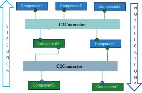
Figure 1. An example of C2 Style
2.2
C2 an architectural styleC2 is a message-based architectural style for develop-ing flexible and extensible software system. It is based on layered of concurrent components linked by connec-tors in accordance with a set of rules [17]. Communica-tion among components is done by implicit invocaCommunica-tion. The principle of this style is to provide limited visibil-ity among components. A component in a C2 style is only aware of services provided by components above it in the hierarchy. A component is completely unaware of services provided by components beneath it.
In a C2 style, a component placed at the bottom layer utilizes the services of components above it by sending a request message. Components on the upper layer emit the notification messages when they change their states. C2 connectors broadcast notification messages to every component and connector present at the bottom layer. Thus, notification messages represented as an implicit invocation mechanism, enable several components to re-act to a single component’s state change [18]. Figure 1 shows the example of C2 style developed in a tool known as AcmeStudio. An architectural interchange language models an architectural styles using AcmeStudio. This tool does not support C2 style. The Figure 1 is designed using an event-based style; because C2 style is much sim-ilar to event-based style. Above figure has seven compo-nents, two C2 connectors, and nine links. Component6 and component7 send only request messages to upper layer components, whereas component1, component2, and component3 broadcast only notification messages to the lower layer components. Component4 and compo-nent5 send request messages and broadcast notifications to upper layer components and lower layer components respectively.
2.3
ComponentA software component is an architectural element that encapsulates processing and data in a system’s architec-ture. It restricts access to a subset of the system’s func-tionality and/or data via an explicitly defined interfaces. It can be deployed independently [19]. A software com-ponent has a set of runtime interfaces, known as a port. The port allows the points of interactions between the component and connector. The Alloy notation of the component is given below:
sigComponent { ports : setPort }
2.4
ConnectorIn a complex and distributed heterogeneous environ-ment interaction may become more important and chal-lenging than the functionality of the individual compo-nents. A software connector has the task of effecting and regulating interactions among components. It also pro-vides application-independent interaction facilities. A connector has set of roles that identify the components and connectors in the interaction. The Alloy notation of connector is given below:
sigConnector { roles : setRole }
2.5
PortIt is not possible in current component models to deal separately with an element of an interaction point when such an element is needed alone for specifying a specific logic [20]. A port defines the points of interaction of a component with its environment. Components with complex interfaces are overloaded with many different ports. The Alloy notation of port is given below:
sigPort { component : oneComponent }
2.6
Roleof roles that are connected to specific ports. The roles are used to specify which interfaces of the port are being used. The Alloy notation of role is given below:
sigRole { Connector : oneConnector }
3
Related Work
Kim and Garlan [21] have mentioned about mapping of an architectural style into a relational model. They expressed an architectural style using formal modeling language Alloy can be checked for properties such as whether a style is consistent, whether a style satisfies some logical constraints over the architectural structure, whether two styles are compatible for composition, and whether one style refines another or not. Wong et al. [22] presented a technique to support the design and verification of software architectural models using the model checker Alloy Analyzer. They presented use of the architecture style library in modeling and verify-ing a complex system that utilizes multi-style structures. Heyman et al. [23] illustrated the need of formal mod-eling techniques for software architect who need to pre-cisely ascertain the security properties of their design models. They have proposed a technique that moti-vates an architect to easily develop, secured architecture designs by assembling already verified security pattern models.
Keznikl et al. [24] presented an approach for auto-mated resolution of connector architectures based on constraint solving techniques (ARCAS). They used a formal modeling language Alloy for describing a connec-tor theory. They employed a constraint solver to find a suitable connector architecture as a model of the theory. Bertolino et al. [25] illustrated software architecture-based analysis, evaluation, and testing. Zhang et al. [26] described the formal syntax of the Wright archi-tectural description language together with its opera-tional semantics in Labeled Transition System (LTS). They presented an architectural style library that em-bodies commonly used architecture patterns to facilitate the modeling process. They had considered the Teleser-vices and Remote Medical Care System (TRMCS), as case study.
Pahl et al. [2] presented an ontological approach for architectural style modeling based on description logic as an abstract, meta-level modeling instrument. They introduced ontologies as a mechanism described and for-mally defined architectural styles. Hansen and Ingstrup [27] have presented an application of the Alloy modeling
language to model architectural change. They demon-strated that it is possible to model architectural change in a relational, first-order language with both a static and dynamic model of architectural runtime structure and architectural runtime change respectively. Bagheri et al. [28] described the feasibility of automated compu-tation of architectural descriptions with an executable prototype developed in Alloy. First, they identified the behavior of architecture as an independent variable. Subsequently a conceptual architecture to make this idea precise, including a graphical notation showing how the key concepts relate to each other.
4
Proposed Work
4.1
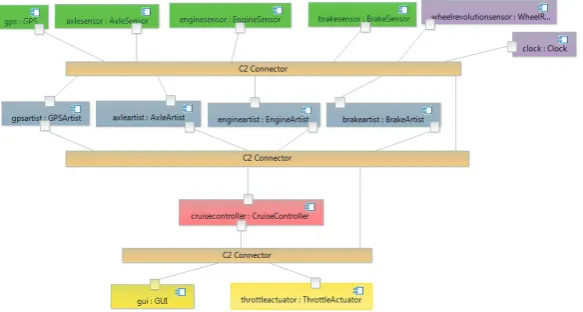
Application of C2 style on a case studyA cruise control system (CCS) has been considered as a case study. It is a safety critical real-time system typi-cally aims to increase passenger safety. It is designed for a car with an automatic transmission. An architectural style C2 is used in structuring embedded control appli-cations. Figure 2 shows the architecture of cruise control system in C2-style. The components in this style are or-ganized in a layered structure. In this example there are five sensors at the top layer of the cruise control system. The Global positioning system (GPS) senses the location and time information. The axle sensor senses number of pulses per rotation of the axle. The engine sensor senses signals when the engine switches on and off. The brake sensor senses signals when the brake is pressed and an-other signal when it is released. The wheel revolution sensor senses the number of revolution of wheel.
The component clock generates a pulse when sensors change their state. There is a facility of implicit feedback in such applications via the external environment.
con-troller to calculate speed and compared it with desired speed. Cruise controller requests for data from sensors to perform computations. By notification messages, sen-sors broadcast data to it. After performing computation cruise controller broadcast calculated values to different actuators i.e., throttle actuator and GUI. The throttle actuator sends request message for required data and listen to the cruise controller for notifications. In C2-style, components are independent, concurrent message generators and/or consumers. Whereas connectors are message routers that may filter, translate, and broadcast messages such as requests and notifications.
4.2
Specifying C2 style of Cruise Control Sys-tem using AlloyModeling a software or a hardware system using for-mal method Alloy has several advantages. Alloy pro-vides formal model in an executable form which ensures that model has unambiguous and testable semantics. Model generator Alloy Analyzer translates high-level, declarative, relational expressions of the formal model into a SAT formula that can be solved by different SAT solvers such as, SAT4J, Zchaff, MiniSAT etc. [29]. Al-loy is also helpful to visualize a model of unbounded size and later specifies a size in a bounded form when verifying properties. To make the explanation more pre-cise, formal method Alloy is used for specifying essential properties of the cruise control system represented in C2-style. Behavioral properties of cruise control system can be expressed as a form of logical predicates which can be analyzed by using the tool Alloy Analyzer [30].
The following Alloy specification of cruise control sys-tem has a module Cruise Control Syssys-tem to split a model among several modules. Amodulein Alloy allows constraints to be reused in different contexts. There are four enumerations such as,FuelLevel, Speed, Brake, and Acceleratorhave been considered. Like asignature, enu-merationcan also contain a set of atoms. In the process of analysis, Alloy Analyzer selects all instances for the givenscope. Therefore the number of atoms become very large that an explicit enumeration would be infeasible. Alloy Analyzer uses pruning techniques (analysis tech-nique) in order to rule out whole sets of atoms at once. First enumerationFuelLevel is used to specify fuel level of engine. EnumerationsSpeed, Brake, andAccelerator are used to indicate the status of speed (LowSpeed or ConstSpeed or HighSpeed), state of brake (ON or OFF), and state of accelerator (Pushed or UnPushed) respec-tively.
moduleCruise Control System enumFuelLevel {LOW,HIGH}
enumSpeed {LowSpeed,ConstSpeed, HighSpeed} enumBrake {ON,OFF}
enumAccelerator {Pushed,UnPushed} sigNotification extends Port {} sigNotifier extendsRole {} sigRequest extendsPort {} sigRequester extendsRole {} abstract sigCruiseControlSystem {
comps : set Component,
conns : set Connector,
c2cons : setC2Connector }
sigComponent {
ports : set Port }
sigC2Connector {
c2port : setPort }
sigConnector {
roles : setRole,
attach : Role one−> onePort }
sigPort {
component : oneComponent,
Figure 2. Cruise Control System in C2 architectural style
sigRole {
connector : oneConnector,
owner : oneConnector,
attachTo : lonePort }
abstract sigSensor extends Component {} one sigGPS extendsSensor
{
specifygpsN : set Notification,
sendG : Notification−>GPSArtist }
one sigAxleSensor extendsSensor { specifyaxleN : setNotification,
sendA : Notification−>AxleArtist,
senseA : Accelerator }
one sigEngineSensor extends Sensor { specifyengineN : setNotification,
sendE : Notification−>EngineArtist,
senseE : FuelLevel }
one sigBrakeSensor extendsSensor { specifybrakeN : set Notification,
sendB : Notification−>BrakeArtist,
senseB : Brake }
one sigWheelRevolutionSensor extends Sensor { specifyWRSN : setNotification,
sendW : Notification−>EngineArtist,
senseW : Speed }
In this Alloy specification, four signatures have been considered such as, Notification, Notifier, Request, and Requester for communication among the components us-ing message passus-ing. Message passus-ing between compo-nents is only done byrequest andnotification messages. In this Alloy model, another signature is a CruiseCon-trolSystem which represents the whole system in terms of components, connectors, and C2-connectors. An ar-chitectural style is a collection of components and con-nectors. Each component has a set of ports to connect with different connectors. Similarly, each connector has a set of roles to connect with the ports of a component. The fieldownerin the port and role signatures indicates that each role and each port have single owner; because a port is owned by single component and a role is owned by single connector.
the speed of a vehicle.
abstract sigDepiction {} sigArtist extendsComponent {}
abstract sigController extendsComponent {} abstract sigActuator extendsComponent {} sigGPSArtist {
specifyGAR : set Request,
specifyGAN : setNotification,
update : Depiction,
sendRequest : GPS,
broadcastNotifi : CruiseController +GUI }
sigAxleArtist {
specifyAAR : setRequest,
specifyAAN : setNotification,
update : Depiction,
sendRequest : AxleSensor,
broadcastNotifi : CruiseController +GUI }
sigEngineArtist {
specifyEAR : setRequest,
specifyEAN : setNotification,
update : Depiction,
sendRequest : EngineSensor,
broadcastNotifi : CruiseController +GUI }
sigBrakeArtist {
specifyBAR : set Request,
specifyBAN : set Notification,
update : Depiction,
sendRequest : EngineArtist,
broadcastNotifi : CruiseController +GUI }
one sigGUI, ThrottleActuator extends Actuator {
specifyAReq : setRequest }
one sigCruiseController extends Controller {
specifyCN : setNotification specifyCR : set Request }
{
Sensor =GPS + BrakeSensor+ AxleSensor + EngineSensor+
WheelRevolutionSensor Actuator =GUI + ThrottleActuator }
Four artist components are specified in the above Alloy specification such as, GPSArtis, AxleArtist,
En-gineArtist, and BrakeArtist for maintaining the states of abstract graphical objects. The artist components receive notification messages of sensor’s state change, causing them to update their depiction. GPSArtist com-ponent has five fields such as specifyGAR, specifyGAN, update,sendRequest,broadcastNotifi. The first field spec-ifyGAR represents a set of request messages for the top layer components. The fieldspecifyGAN represents a set of notification messages for bottom layer components. The Third field update indicates the state changed of sensor component in the form of depiction. In architec-tural style C2, a component has all requisite informa-tion about the upper layer components, whereas it has no information about bottom layer components. Hence, an artist components send request messages to a spe-cific upper layer component and broadcast notifications to all components placed at the layer below it, from that component’s layer. Fourth field sendRequests indi-cates request messages sent from this artist component to only GPS component. WhereasbroadcastNotifi field represents notification message sent from this compo-nent to controller and actuator compocompo-nents. Similarly, other artist components also have five fields for showing relationship with other components.
In C2-style of cruise control system, cruise controller is the main component. Hence, cruise controller sends and broadcasts both requests and notifications to the upper layer components as well as lower layer compo-nents respectively. It has two fields such as specifyCN and specifyCR in order to represent a set of notifica-tions and requests respectively. C2-style of cruise con-trol system has two actuators such as, GUI and throt-tle actuator for receiving data, sent from upper layer components. These actuators can specify only requests messages, because the bottom layer components send only request messages to upper layer components. In formal method Alloy, ’+’ operator is used for the union operation. Hence, sensor shows the union of all sensor components and actuator shows the union of all actuator components those are used in this style.
4.3
Analysis of dynamic behavior of architec-tural style C2portroleowner is a first fact. It indicates that if a port is present in the component, it means that this port is owned by the component and the component is the owner of this port. Similarly, if a role is present in the connector, it means that this role is owned by the con-nector and the concon-nector is the owner of this role. In the first fact, name is given but in second fact name is not specified. In Alloy, fact name is optional. The second fact indicates that if some roles are related to some ports then these roles should be specified by some connectors.
According to the principles of C2-style, two compo-nents cannot directly be connected. If one component wants to communicate with other components, it must be connected through a C2-connector. In C2-style ar-chitecture, C2-connector is a combination of more than one simple connector. Hence, it can be viewed that C2-connector acts as a component having a set of ports to connect with other simple connectors having set of roles. AssertionNo comp connect comp, analyzes that, if some roles are attached to other some ports and the first port owned by any component and also the second port is owned by any other component, Alloy Analyzer generates counterexamples.
There are certain constraints that a developer does not want to record them as facts. If a developer wants to analyze the model with other constraints, and also to check whether these constraints are related to some other constraints or not. Predicate expressions are used to achieve all these. A predicate is a logi-cal formula with declaration parameters. Predicate de-scribes a set of states and transitions, by using con-straints among signatures and their fields. Without using predicate, instances cannot be generated for op-eration except from counterexample. Following code have two predicates such as Port Connect Role and Comp Connect C2Con to specify port-role connection and component to C2-Connector attachment operations. PredicatePort Connect Roleis used for a port and role, returning value true if they are directly connected. In predicateComp Connect C2Con, constraints are added to connect component and C2-Connector. The keyword disj is used to restrict the bindings and include ones in which the bound variables are disjoint from one an-other. In this specification,disj indicates that between two roles only one is used. In the second predicate, first predicate is used, because predicates in Alloy act as built-in functions and it can be easily used by other predicates.
factPortRoleOwner {
∼ports = component && ∼roles = connector }
fact {
allconnector1,connector2 : Connector | somerole1,role2 : Role |
someport1, port2 : Port |
role1−> port1inconnector1.attach &&role2−> port2 inconnector2.attach }
assertNo comp connect comp{ allrole1,role2 : Role | allport1,port2 : Port |
somecomponent1,component2 : Component | Port Connect Role[role1,port1] && Port Connect Role[role2,port2] && owner[port1] = component1 =>
owner[port2] ! = component2 }
predPort Connect Role [role : Role,port : Port] {
role−> port in Connector.attach }
predComp Connect C2Con [comp : Component,
c2con : C2Connector] {
somerole1,role2 : Role | someport1, port2 : Port | disj[role1,role2] &&
Port Connect Role[role1,port1] &&owner[port1] = comp
&&Port Connect Role[role2,port2] &&owner[port2] = c2con
&&owner[role1] = owner[role2] }
also low, then engine sensor component broadcast noti-fication message to artist component.
factaxle sensor Notification {
allwrs : WheelRevolutionSensor,
axle : AxleSensor |
somen : Notification,a : AxleArtist | wsr.senseW = HighSpeed &&
axle.senseA=UnPushed impliesaxle.sendAinn−> a }
factengine sensor Notification {
allwsr : WheelRevolutionSensor,
engine : EngineSensor |
somen : Notification,e : EngineArtist | wsr.senseW = LowSpeed &&
engine.senseE = LOW
impliesengine.sendE inn−> e }
In the following Alloy model,Define signature is used to restrict the model to generate only one system in-stance. The predicateType-Definition specifies the def-inition of architectural elements and their types. Key-wordunivis an unary operator represented as universal set. Style Consistency Checking predicate specifies the type definition of notification and request signatures. In this study, Notification and Request are considered as a port andNotifier and Requester are considered as a role. First constraint considersDefine as aNotification attached by a Notifier (it is a type of role). Similarly, in next the constraint, Define is considered as Request attached by a Requester. Other two constraints are in-versely related to first two constraints.
Third constraint consideredDefineas a role (Notifier) to attach with the portNotification. In this constraint, it is specified that the number of link between a role (No-tifier) and a port (Notification) should be one. Fourth constraint is similar to third constraint for port request and role requester.
one sigDefineextendsCruiseControlSystem {} predTypeDefinition[archElement : univ,
elementType : set univ] {
archElementinelementType }
predStyle Consistency Checking[] {
allDefine : Notification | (allrole:Define.∼attachTo |
TypeDefinition[role,Notifier]) allDefine : Request |
(allrole : self.∼attachTo |
TypeDefinition[role,Requester]) allDefine : Notifier |
(#(Define.attachTo) = 1) && (allport : Define.attachTo |
TypeDefinition[port, Notification]) allDefine : Requester |
(#(Define.attachTo) = 1) && (allport : Define.attachTo |
TypeDefinition[port,Request]) }
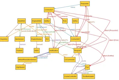
runStyle Consistency Checking for3
Figure 3. Instances generated by Alloy Analyzer
4.4
Performance evaluation for different
SAT solvers
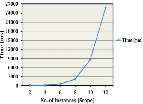
[image:11.595.296.543.142.202.2]To analyze the performance of analysis, the consis-tency on Alloy specification of cruise control system con-sidering problem size from 2 to 12 has been performed. For the performance evaluation, system configuration is Intel(R) Core(TM) i5-2400 CPU @ 3.10 GHz, 2.00 GB (1.88 GB usable), 32-bit Windows 7 operating sys-tem. Execution is carried out using Alloy Analyzer 4.2, build date: 2012-04-20 10:05 EDT. During execution process, SAT solver is SAT4J where maximum stack to use was 8192k and maximum memory to use was 768M. For problem size 2 to 10 above details are used; when the execution performed for problem size 12, Alloy Ana-lyzer generates an error message related to memory used. Hence for problem size 12, maximum memory 1024M is used. The performance result for different bound range (from 2 to 12) is shown in Figure 5. As shown in Fig-ure 5, for problem size 12 time reach its limit of tractabil-ity for C2-style.
Figure 5. Performance evaluation for SAT4J solver
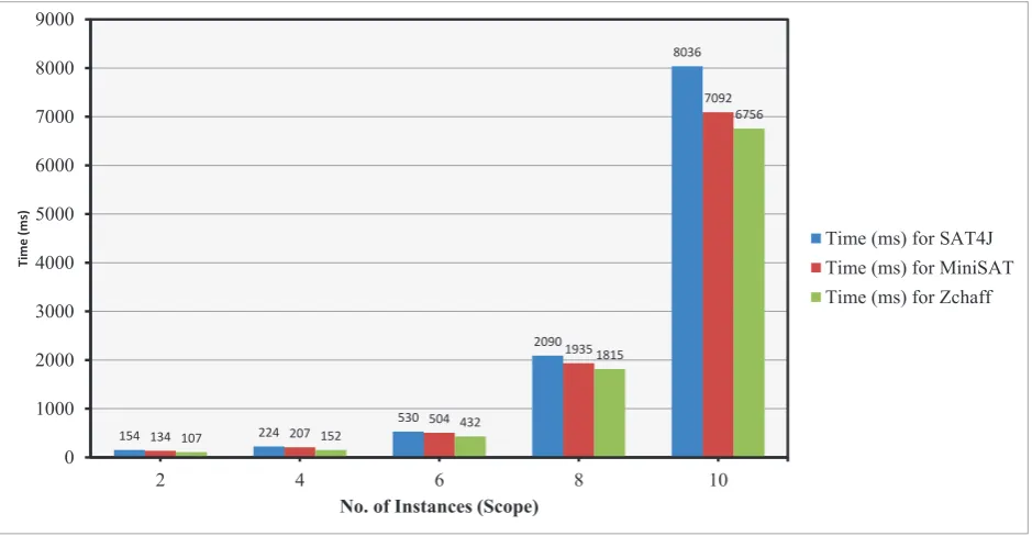
The Alloy Analyzer supports many SAT solvers such as MiniSat, MiniSat with Unsat Core, ZChaff, and SAT4J to exhaustively search for satisfying models or counterexamples. The comparative analysis among these solvers for bound range 7, maximum memory used 768, maximum stack used 8192k is presented in ta-ble:1. Finally the comparison of performance evalua-tion among these solvers is also presented in Figure 6 for bound range from 2 to 10 with same system config-uration.
There are many advantages of analyzing different lev-els of abstractions of an architectural style such as
in-Table 1. Performance analysis for different SAT solvers
S. No. SAT Solver Time (ms) No. of vars.
1. MiniSat 982 134306
2. MinisatProver 1407 134305
3. ZChaff 915 134306
4. SAT4J 1104 134306
ternal functioning of component and connector, topol-ogy of architectural elements, and principle of the archi-tectural style. The first advantage is to provide more understandability for developer to implement different components and connectors. Second advantage is to provide a framework that is helpful for deployment pro-cess. Third advantage provides an appropriate level of granularity for accessing non-functional properties of a software system. The use of formal modeling techniques ensures the correctness of any architectural changes per-formed by an architect. In this study, it is inferred that analysis of dynamic aspects of any style needs to be car-ried out to assess the correctness.
5
Conclusion
In this paper, a study on a safety critical system called as cruise control system using a complex architectural style C2 is presented. Subsequently a library of styles is presented using formal modeling language Alloy to assist the reuse and extensible modeling of complex and highly distributed components, developed in different program-ming languages. This style library is used to model the cruise control system. Compatibility among compo-nents, connectors, and C2-connectors has been checked using formal verifier Alloy Analyzer. Finally, perfor-mance evaluation among different SAT solvers have been performed in order to assess the efficiency of Alloy Ana-lyzer. In this study, Alloy is chosen because it provides a compact model that allows the verification of structural and behavioral properties of a system. Modeling the structural properties of an architectural style has gener-ally been associated with the component-connector ab-stractions. Styles are generally used to promote design reuse, code reuse, and support interoperability between two different styles. Hence, from the above study, it is concluded that, formalizing an architectural style pro-vides style consistency and validity of configuration. It also helps in refinement of critical processes and check-ing compatibility among different style.
[image:11.595.45.284.405.578.2](REpresen-154 224
530
2090
8036
134 207
504
1935
7092
107 152
432
1815
6756
0 1000 2000 3000 4000 5000 6000 7000 8000 9000
2 4 6 8 10
T
im
e
(
m
s)
No. of Instances (Scope)
[image:12.595.71.541.128.372.2]Time (ms) for SAT4J Time (ms) for MiniSAT Time (ms) for Zchaff
Figure 6. Performance evaluation for different SAT solvers
tational State Transfer) architecture etc. The formal models can be verified using model checkers such as Al-loy Analyzer, CPN Tools, and PAT (Process Analysis Toolkit). The verification process may also be carried out considering different architectural patterns such as state-logic-display, Model-View-Controller (well known as MVC pattern), and Sense-Compute-Control etc.
REFERENCES
[1] R. N. Taylor, N. Medvidovic, and E. M. Dashofy. Soft-ware architecture: foundations, theory, and practice. Wiley Publishing, 2009.
[2] C. Pahl, S. Giesecke, and W. Hasselbring. Ontology-based modelling of architectural styles.Information and Software Technology, 51(12):1739–1749, 2009.
[3] N. Medvidovic and R. N. Taylor. A classification and comparison framework for software architecture de-scription languages. IEEE Transactions on Software Engineering, 26(1):70–93, 2000.
[4] D. C. Luckham, J. J. Kenney, L. M. Augustin, J. Vera, D. Bryan, and W. Mann. Specification and analysis of system architecture using rapide. IEEE Transactions on Software Engineering, 21(4):336–354, 1995.
[5] R. Allen and D. Garlan. A formal basis for architectural connection. ACM Transactions on Software Engineer-ing and Methodology (TOSEM), 6(3):213–249, 1997.
[6] J. Woodcock, P. G. Larsen, J. Bicarregui, and J. Fitzgerald. Formal methods: Practice and expe-rience. ACM Computing Surveys (CSUR), 41(4):19, 2009.
[7] R. Jhala and R. Majumdar. Software model checking.
ACM Computing Surveys (CSUR), 41(4):21, 2009.
[8] D. Jackson.Software Abstractions: logic, language, and analysis. MIT press, 2006.
[9] H. Gomaa. Software Design Methods for Concurrent and Real-Time Systems. Addison-Wesley, 2001.
[10] S. D. Group. Alloy analyzer 4.http://alloy.mit.edu/
alloy4/, 2010.
[11] D. Garlan, R. Monroe, and D. Wile. Acme: an architec-ture description interchange language. InProceedings of the 1997 conference of the Centre for Advanced Studies on Collaborative research, pages 159–173. IBM Press, November 1997.
[13] J. Kofroˇn, F. Pl´aˇsil, and O. ˇSer`y. Modes in component behavior specification via EBP and their application in product lines. Information and Software Technology, 51(1):31–41, 2009.
[14] S. Malek, N. Medvidovic, and M. Mikic-Rakic. An ex-tensible framework for improving a distributed software system’s deployment architecture. IEEE Transactions on Software Engineering, 38(1):73–100, 2012.
[15] N. Medvidovic and G. Edwards. Software architecture and mobility: A roadmap.Journal of Systems and Soft-ware, 83(6):885–898, 2010.
[16] J. M. Spivey.The Z notation: a reference manual. Pren-tice Hall International (UK) Ltd., 1992.
[17] H. Muccini, M. Dias, and D. J. Richardson. Software architecture-based regression testing. Journal of Sys-tems and Software, 79(10):1379–1396, 2006.
[18] P. Oreizy, M. M. Gorlick, R. N. Taylor, D. Heimhigner, G. Johnson, N. Medvidovic, A. Quilici, D. S. Rosen-blum, and A. L. Wolf. An architecture-based approach to self-adaptive software.Intelligent Systems and Their Applications, IEEE, 14(3):54–62, 1999.
[19] I. Crnkovic, S. Sentilles, A. Vulgarakis, and M. R. Chau-dron. A classification framework for software compo-nent models.IEEE Transactions on Software Engineer-ing, 37(5):593–615, 2011.
[20] D. Bennouar, T. Khammaci, and A. Henni. A new ap-proach for component’s port modeling in software archi-tecture. Journal of Systems and Software, 83(8):1430– 1442, 2010.
[21] J. S. Kim and D. Garlan. Analyzing architectural styles.
Journal of Systems and Software, 83(7):1216–1235, July 2010.
[22] S. Wong, J. Sun, I. Warren, and J. Sun. A scalable approach to multi-style architectural modeling and ver-ification. InProceedings of the 13th IEEE International Conference on on Engineering of Complex Computer Systems, ICECCS ’08, pages 25–34, Washington, DC, USA, 2008. IEEE Computer Society.
[23] T. Heyman, R. Scandariato, and W. Joosen. Reusable formal models for secure software architectures. In Pro-ceedings of the 2012 Joint Working IEEE/IFIP Confer-ence on Software Architecture and European ConferConfer-ence on Software Architecture, WICSA-ECSA ’12, pages 41– 50, Washington, DC, USA, 2012. IEEE Computer So-ciety.
[24] J. Keznikl, T. Bureˇs, F. Pl´aˇsil, and P. Hnˇetynka. Auto-mated resolution of connector architectures using con-straint solving (ARCAS method).Software and Systems Modeling, Springer, pages 1–30, 2012.
[25] A. Bertolino, P. Inverardi, and H. Muccini. Soft-ware architecture-based analysis and testing: a look into achievements and future challenges. Computing, Springer-Verlag, 95(8):1–16, 2013.
[26] J. Zhang, Y. Liu, J. Sun, J. S. Dong, and J. Sun. Model checking software architecture design. InProceedings of the 2012 IEEE 14th International Symposium on High-Assurance Systems Engineering, pages 193–200, Wash-ington, DC, USA, 2012. IEEE Computer Society.
[27] K. M. Hansen and M. Ingstrup. Modeling and analyzing architectural change with alloy. In Proceedings of the 2010 ACM Symposium on Applied Computing, SAC 10, pages 2257–2264, New York, NY, USA, 2010. ACM.
[28] H. Bagheri, Y. Song, and K. Sullivan. Architectural style as an independent variable. In Proceedings of the IEEE/ACM international conference on Automated software engineering, ASE 10, pages 159–162, New York, NY, USA, 2010. ACM.
[29] M. W. Moskewicz, C. F. Madigan, Y. Zhao, L. Zhang, and S. Malik. Chaff: Engineering an efficient SAT solver. In Proceedings of the 38th annual Design Au-tomation Conference,New York, NY, USA, pages 530– 535. ACM, 2001.