© 2017, IRJET | Impact Factor value: 5.181 | ISO 9001:2008 Certified Journal | Page 1976
A Finite Element Thermo-Mechanical Stress Analysis of IC Engine
Piston
Manish Kumar
M.Tech., Dept. of Mechanical Engineering HBTI Kanpur, India
---***---Abstract -
A piston is a component of reciprocating engines, pumps and gas compressors. It is located in a cylinder and is made gas-tight by piston rings. Engine pistons are one of the most complex components among all automotive or other industry field components. Piston and connecting rod are connected by the piston pin at one end of connecting rod and other big end of connecting rod than connected to crankshaft. Pistons are subjected to forces generated by hot burned gases on fuel combustion and in high temperature combustion chamber. These two causes result in thermal and mechanical stresses. Mechanical stresses appear due to gas force and thermal stresses due to high temperature of combustion. In the present work, the thermal boundary conditions are obtained to calculate the temperature distribution and thermal stress in piston. The analysis is carried out to identify the maximum and minimum stress location in piston. The modeling of piston is carried out in CATIA software whereas ANSYS workbench is used for the Finite Element Analysis. Von Mises stresses criterion is used in Finite element analysis.Key Words: Piston, Thermo-mechanical, Stress, Temperature, Heat Transfer Coefficient
1. Introduction
Pistons are subjected to forces generated by hot burned gases on fuel combustion and in high temperature combustion chamber. These two causes result in thermal and mechanical stresses. Mechanical stresses appear due to gas force and thermal stresses due to high temperature of combustion; therefore, a piston must be capable of transmitting the kinetic energy of high gas pressure and temperature. The piston is subjected to the varying pressure and temperature by the gases and inertia forces due to the acceleration/retardation in a cycle. The piston behaviour affected by thermal-mechanical stresses phenomenon due to cyclic thermal and mechanical loadings. The objective of present work is to predict the temperature distribution and stresses due to thermal and mechanical loadings for the conventional pistons. The analyses are carried out to identify the critical location of stresses and deformations.
1.1 Literature Review
C.S. Wang et al. discussed a heat transfer model that used quasi-steady heat flux relations to calculate the heat transfer from combustion gases through cylinder wall to the coolant in an internal combustion engine to calculate the components temperature distribution [2].T. Morel et al. showed the temperature and heat flow distribution
analytically of an S.I. engine. Douglas M. Baker et al. discussed about a methodology for a coupled thermodynamic and heat transfer analysis for diesel engine with 1-D and 2-D heat flow finite element models to find the piston and liner temperatures and heat transfer rate [4]. Mahdi Hamzehei et al. measured the temperature of piston and cylinder head in a 4-cylinder gasoline engine at actual process [6]. Krisztina Uzuneanu et al. modeled the heat transfer in the piston head of a spark ignition engine supplied with ethanol-gasoline blend using simple thermal networks to multidimensional differential equation modeling [7]. Yanxia Wang et al. investigated the thermo-mechanical coupling of piston using ANSYS software to find the temperature and stress distribution [8]. Dr. Ahmed beiruti et al. discussed the analytical study on the thermal effects on the diesel engine piston and its compression rings during the contact between the piston and rings with three dimensional finite element method using ANSYS software [9]. P. Gudimetal et al. analyzed the finite element analysis of reverse engineered internal combustion engine piston using ANSYS package [10].
1.2 Temperature Field and Stress Locations
The piston is used to take the load from the combustion gases and transfer it to crankshaft through connecting rod for the rotational motion in an engine, It should be strong enough to remain rigid under loading, and also be light enough to reduce the inertia forces which are produced when the connecting rod and piston stop, change directions and start again at the end of each stroke.
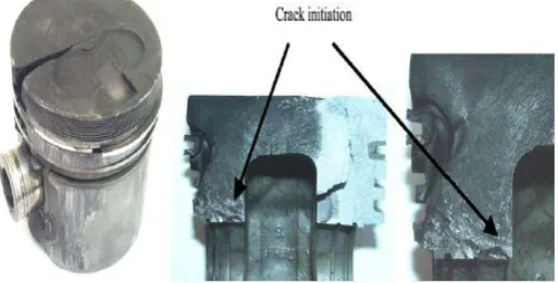
[image:1.595.309.566.605.735.2]Piston is under the high thermal load and mechanical load. Thus the stresses in the piston are found greatly near the piston pin areas. [1]
© 2017, IRJET | Impact Factor value: 5.181 | ISO 9001:2008 Certified Journal | Page 1977
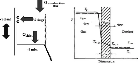
2. Engine Heat Transfer
[image:2.595.57.266.210.346.2]Heat transfer analysis of engine is carried out using convection heat transfer, to calculate the heat transfer coefficient and ambience temperature on piston boundaries. A theoretical model is taken for the study with engine specifications as shown in Table 1.
Table 1: Engine specifications
Bore 80 mm
Stroke 110 mm
Connecting Rod 234 mm
Compression Ratio 16.5
Rated Power 3.7 kW @ 1500 RPM
SFC 245 g / kW h
The heat in engine is generated on combustion of fuel. Heat is transferred by all three modes. Heat is transferred by conduction through the cylinder head, cylinder walls, and piston; through the piston rings to the cylinder wall; through the engine block and manifolds. Heat is transferred by forced convection between the in-cylinder gases and the cylinder head, valves, cylinder walls, and piston. Heat exchange by radiation occurs through the emission and absorption of electromagnetic waves. Only convection heat transfer is taken into account in present work to obtain piston thermal boundary conditions to predict temperature within the piston to calculate the thermal stresses. A typical heat transfer path [5] is shown in Figure 2.
Figure 2: Convection heat transfer from gas to coolant
2.1 Steady state heat transfer modeling
Gas temperature is a function of crank angle in an engine and varies with crank angle. So, for steady state thermal analysis in this work the following relationship to obtain mean gas temperature at mean gas pressure [5],
Tgm =
The conditions at coolant side [11], wall thickness, wall thermal conductivity, molar mass and density of combustion gases are given in Table 2. The average heat transfer coefficient at the gas side is calculated with assumption Nusselt, Reynolds and Prandtl number relationship for turbulent flow in pipes and over flat plates [5]:
Nu =
a
Rem PrnIn present work, the mean heat transfer coefficient is calculated from empirical relationship of Nusselt’s equation [12] at mean pressure and bulk gas temperature.
2 1 4 3 3
5.41 10
(1 1.24
)
m m
[image:2.595.309.559.279.404.2]h
P Tg
C
Table 2: Physical & Thermal properties of materials
Parameter Value
Bulk gas temperature, Tgm 1162 K
Gas heat transfer coefficient, hm 293 W/m2K
Cylinder wall temperature, Twg 245 0C
Wall thermal conductivity, k 46 W/mK
Wall thickness, tw 6 mm
Water temperature, Tcm 80oC
Water heat transfer coefficient, hc 1400 W/m2K
Molar mass of combustion gas, M 29 kg/KMole Combustion gas density 1.127 kg/m3
2.2 Thermal Boundary Conditions
In this work, finite element thermal analysis is carried out to calculate the piston temperature with the help of third kind boundary condition as below [13]:
(
f)
T
k
h T
T
n
Where, T is the surface temperature, n is the exterior normal vector for the object boundary, h is the convection heat transfer coefficient, k is the thermal conductivity of object and Tf is the ambience temperature at the boundary of the
object.
[image:2.595.38.263.526.631.2]© 2017, IRJET | Impact Factor value: 5.181 | ISO 9001:2008 Certified Journal | Page 1978 Figure 3: Surfaces of the heat exchange of the piston
The boundary conditions are calculated of piston surfaces from literature with numerical means of surfaces from A to H as figure 3, At piston crown face, A: Ambience Temperature is bulk gas temperature and gas side heat transfer coefficient. Ring land surface, B: Since there is a small gap between piston crown and the liner, the captured gas temperature is the mean temperature of thecrevice surfaces [14]. Therefore, the heat is conducted through the gas with the convective heat transfer coefficient:
k
h
Where
is crevice clearance, 0.5 mm for the present work, for k = 0.047 W/ m KIt gives, h = 94 W/ m2 K, and the ambience temperature at
this face is taken as the wall temperature.
Ring groove face, C: the rings are placed to make a tight seal for gases. The heat transfer modeling in this region is obtained through ring resistance approach. The oil film resistance R2 is neglected in this face. The heat transfer in
rings is shown in Figure 4:
Figure 4: Thermal circuit of heat transfer resistances in the region of the rings
Where, R1: conductive resistance of the ring, R2: conductive
resistance of the oil film is negligible, R3: conductive
resistance of the liner, R4: convective resistance between the
liner and the cooling water. The resistances are:
2 1 1
1
ln( / )
2
kringr
r
R
L
, conductive resistance of the ring4 3 3
3
ln(
/ )
2
linerr
r
R
L k
, conductive resistance of the liner
4
1
water s
R
h
A
, convective resistance between the linerand the cooling water
Where, r1, r2, r3 and r4 are inner radius of ring, outer radius of ring, bore radius and inner radius of water-jacket, respectively. L1, L2 and L3 are the widths of the heat transfer
paths, respectively.
The effective heat transfer coefficient is obtained from,
1
efftot eff
h
R A
Where, Aeff is the piston surface in contact with the ring and
Rtot is the total resistance. Other ring land D and E: the heat
transfer coefficient at this face is taken as the one third of the gas heat transfer coefficient and the ambience temperature is the 69.5 % and 66.5% of the first ring land temperature for D and E respectively [15]. Skirt F; The heat transfer at this face through convection with low coefficient [16]. Piston underside heat transfer G and H: the piston underside is divided into two regions: Region G and H, the crown underside is cooled by splash cooling type. The ambience temperature is taken in this region the oil temperature [15]. The value of convective heat transfer coefficient is calculated from the following equations,
0.35
900
4600
H
RPM
h
0.35
240
4600
G
RPM
h
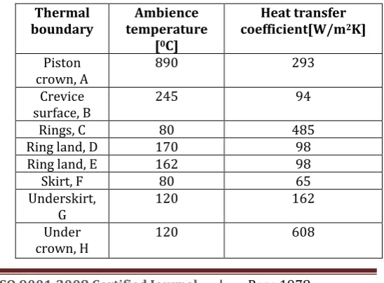
[image:3.595.64.264.521.629.2]The surface boundary conditions, heat transfer coefficient and gas temperature ambience to the piston surface for given Figure 3 are calculated as given in Table 3 below:
Table 3: Piston thermal boundary conditions
Thermal
boundary temperature Ambience [0C]
Heat transfer coefficient[W/m2K]
Piston
crown, A 890 293
Crevice
surface, B 245 94
Rings, C 80 485
Ring land, D 170 98
Ring land, E 162 98
Skirt, F 80 65
Underskirt,
G 120 162
Under
[image:3.595.292.566.585.787.2]© 2017, IRJET | Impact Factor value: 5.181 | ISO 9001:2008 Certified Journal | Page 1979
3. Mechanical Loading on Piston
The stress, strain and deformations are the most serious when the explosive pressure of the fuel gas achieves maximum under the condition of stable rotational speed. Therefore, the research of the stable stress under the maximum explosive pressure is very important [17] and the inertia- forces at the maximum acceleration at the condition of maximum gas pressure at TDC theoretically.
3.1 Gas Pressure Model
[image:4.595.46.275.303.413.2]The gas pressure model is described without the effect of temperature acting on the piston crown, combustion chamber surface, field of fire, ring grooves and so on as shown in Figure 5.
Figure 5: Variation of gas pressure along cylinder axis
[image:4.595.36.277.552.662.2]The maximum explosive pressure is taken as 10 times of mean effective pressure. The maximum gas pressure P is 5.5 MPa for pressure loading on piston top which is the 10 times of mean effective pressure approximately. The values of gas load on the piston are given in Table 4 [18].
Table 4: Gas pressure variation on piston
Boundary field Load Value [MPa]
Piston crown P 5.5
Bottom of first groove P ×76% 4.18
Bottom of the second groove P × 30% 1.65
Bottom of the third groove P× 20% 1.10
3.2
Inertia Force ModelBecause the piston does the reciprocating motion in the cylinder, according to the Dynamics of Engine, this process can produce the reciprocating inertialforce Pj. Its value is proportion to the acceleration of the piston [18]. The mass of the piston is supposed to be concentrated in itscentre of
gravity. The maximum reciprocating inertial force can be calculated as:
2
(1
j j
P
m
R
In ANSYS, the inertial force is not loaded directly, but acceleration is loaded in it. Software calculates the inertial force automatically with take the mass of piston into account. The acceleration is obtained as:
2
(cos
cos 2 )
a
R
Among them,
is the crank angle:
= RPM
/ 30
is the link rod ratio:
= R/L3.3 Constraint Conditions for Mechanical Loading
Three freedom degrees of the piston pin are restrained to let the piston in a static condition to eliminate the revolving of the piston around the piston pin. The selection of the displacement boundary condition is very important to the finite element analysis. If the selection is not correct, it will affect the calculation precision. On the moment of the maximum gas pressure, the pin contacted to the surface of the pin hole [18].
4. Finite Element Analysis
In this section FE based stress analysis piston is carried out using ANSYS Workbench software. The ANSYS software is very important tool for the stress analysis, use to solve the problem related to the structure analysis with complex structure and loading conditions, heat flow analysis, fluid flow analysis and design optimization. In this present work the Steady State Thermal and Static Structural tools of ANSYS software are used to analyze the Thermal and Mechanical stresses.
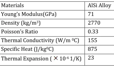
The piston material properties are given in Table 5[15].
Table 5: Material properties of piston
Materials AlSi Alloy
Young’s Modulus(GPa) 71
Density (kg/m3) 2770
Poisson’s Ratio 0.33
Thermal Conductivity (W/m 0C) 155
Specific Heat (J/kg0C) 875
Thermal Expansion ( 10-6 1/K) 23
[image:4.595.336.535.567.682.2]© 2017, IRJET | Impact Factor value: 5.181 | ISO 9001:2008 Certified Journal | Page 1980 Figure 6: Finite element mesh model of piston
5. Results and Discussion
5.1 Piston Temperature Distribution
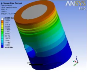
The piston temperature distribution as in Figure 7 changes between 161.90C to 263.890C with the maximum
temperature at the piston top and minimum temperature at the lower part of the piston skirt. At the piston ring land, temperatures are distributed uniformly along the piston in the radial direction. The piston temperature changes uniformly from the piston top to the bottom, without any sharp change phenomenon. The heat absorbed from the gas by the piston crown is generally takes up 2 - 4 % of the total heat of fuel burning [19]. The heat transfer for piston crown for present work is calculated from 0.218 kW to 0.437 kW.
Figure 7: Surface Temperature field of the piston
5.2 Aluminium Alloy Piston Mechanical Stresses
The gas pressure model and inertial forces model given to ANSYS workbench, Displacement constraints are given at the piston pin holes to avoid the motion of the piston.
The value of equivalent von-Mises stress for the Aluminium alloy piston is 199 MPa maximum and 0.11 MPa is minimum value. The maximum stress is on the piston pin hole and greater stress is found on the above portion of piston pin hole. At the piston crown the stress value is nearly 28 MPa. The maximum value of strain and total deformation are 0.0028 mm/mm, and 0.04615 mm respectively.
(a)
(b)
(c)
Figure 8: (a) Equivalent Von-Mises Stress, (b) strain, and (c) deformations of piston
5.3 Coupling Stress in Piston
In this section, the coupling stresses on aluminium alloy piston are calculated. The thermal and mechanical boundary conditions are given into ANSYS work bench. The maximum value of stress near piston pin hole is found 661 MPa maximum at piston pin hole, strain near piston pin hole 0.010387 mm/mm, and total deformation is 0.33243 mm.
[image:5.595.91.234.426.545.2] [image:5.595.362.508.654.775.2]© 2017, IRJET | Impact Factor value: 5.181 | ISO 9001:2008 Certified Journal | Page 1981 (b)
(c)
Figure 9: (a) Stress, (b) strain, and (c) deformations of piston
Conclusions
The maximum temperature is obtained for piston is 161.90C
to 263.890C with the maximum temperature at the piston
top and minimum temperature at the lower part of the piston skirt. The heat flux on piston crown is 78244 W/m.2
The stresses obtained by action of gas pressure and inertia forces; the maximum value of equivalent stresses on conventional piston is 199.03 MPa at near region of piston pin hole and total deformation is 0.046157 mm.
The coupled stresses in piston by temperature, pressure and inertia forces are calculated. Coupled stress for aluminium alloy piston near piston pin hole region is 661.34 MPa. The total deformations are 0.33242 mm near the piston crown face radially.
References
[1] F.S. Silva “Fatigue on engine pistons-A compendium of
case studies,” Engine failure analysis 13(2006), pp. 480-492, doi:10.1016/j.engfailanal.2004.12.023.
[2] C.S. Wang, G F Berry,”Heat transfer in internal
combustion engines”,1985,The American society of mechanical engineers.
[3] R. Nicole, “Title of paper with only first word
capitalized,” J. Name Stand. Abbrev., in press.
[4] Douglas M Baker,”A methodology for coupled
thermodynamic and heat transfer analysis of a diesel engine”,1994,Applied mathematical modeling, vol 18, November , butterworth Heinemann
[5] J.B. Heywood, “Internal combustion engine
fundamentals”, ISBN: 0-07-028637-X, 1998, McGraw Hill Inc.
[6] Mahdi Hamzehei, Manochehr Rashidi, 2006, “
Determination of piston and cylinder head temperature distribution in a 4-cylinder gasoline engine at actual process”, proceedings conf. on Heat transfer engineering and environment, Elounda, Greece, August 21-23,2006, pp. 153-158
[7] Krisztina Uzuneanu,”Modeling the heat transfer in the
piston head of a spark ignition engine supplied with ethanol-gasoline blend,COFRET 08, Jun 11-13,2008, France
[8] Yanxia wang, “ Simulation investigation on the
thermo-mechanical coupling of the QT 300 piston”, 2009. Second international conference on information and computing science, pp 77-80
[9] Dr. Ahamed,” thermal effects on diesel engine piston and
piston compression rings”,2009, Eng & tech journal, vol 27, No. 8 , 2007, pp 1444-1454
[10] Gudimetal P, Gopinath C V, “Finite element analysis of
reverse engineered internal combustion engine piston”,2009, AIJSTPME 2009 2(4), pp 85-92
[11] Imdat Taymaz, “ An analysis of residual stresses in
thermal barrier coatings: A FE performance assessment”, 2009, WILEY-Verlag Gmbh & Co
[12] Toshio Shudo, “ Applicability of heat transfer equations
to hydrogen combustion”, JSAE review, Vol 23 No. 3 2002 pp 303-308
[13] Hongyuan Zhang, Jian Xing, “ Temperature field analysis
to gasoline engine piston and structure optimization”, ISSN: 1992-8645, JATIT Feb 2013, pp 904-910
[14] Ekrem Buyukkaya, “ Thermal analysis of functionally
graded coating AlSi alloy and steel pistons”, 2008, Elsevier Ltd., pp 3856-3865
[15] V. Esfahanian, A. Javaheri, “ Thermal analysis of an SI
engine piston using different combustion boundary condition treatments”, 2005, Elsevier Ltd., 2006, pp 277-287
[16] Hongyuan Zhang, Jian Xing, “ Temperature field analysis
to gasoline engine piston and structure optimization”, ISSN: 1992-8645, JATIT Feb 2013, pp 904-910
[17] Hongyuan Zhang “An analysis to thermal load and
mechanical load coupling of a gasoline engine piston” ISSN: 1992-8645, Journal of theoretical and applied information technology, Vol 48, no. 2, Feb 2013, pp 911-917
[18] Yanxia Wang, Haiyan Shi, “ Simulation and analysis of
thermo-mechanical coupling load and mechanical dynamic load for a piston”, 2010 IEEE, pp 106-110
[19] Vinay V. Kuppast et al. “ Study on influence of