© 2018, IRJET | Impact Factor value: 6.171 | ISO 9001:2008 Certified Journal | Page 2737
Parametric Optimization of Electric Discharge Drill Machine using
Taguchi and ANOVA Approach
1M.Tech Student, Dept of Mechanical Engg, KIT Kanpur, Uttar Pradesh, India 2Professor, Dept of Mechanical Engg, KIT Kanpur, Uttar Pradesh India 3Asst. Professor, Dept of Mechanical Engg, BIT Kanpur Dehat, Uttar Pradesh, India
---***---Abstract -
This experimental study deals with EDM drilling on stainless steel material using copper tubular electrode to drill micro holes. The tool used is a tubular copper electrode of 3mm diameter. EDM oil was used as dielectric medium. The objective of the research is to optimize the process parameters to obtain maximum machining rate and minimum EWR while drilling deep holes using Drill EDM on stainless steel using a tubular copper electrode of 3mm. The study was done by selecting the most prominent parameters i.e. Pulse on time, Pulse off time, Discharge current and fluid pressure with L9 orthogonal array set of experiments and optimizing the responses individually using Taguchi Method & ANOVAKey Words: EDM drilling, Taguchi, ANOVA, hole, MRR, EWR etc.
1. INTRODUCTION
The quality of the product mainly depends upon the material and process parameters. Optimization technique plays a vital role to increase the quality of the product [1]. Design of experiment is considered to be a very useful strategy for accomplishing these tasks [2]. Electrical Discharge Machining (EDM) Drilling is quickly becoming the standard method for producing small, tight tolerance holes. It is an extremely cost-effective method for producing fast and accurate holes into all sorts of whether hard or soft conductive materials [3]. An Electric Discharge Machining is a thermo-electric, spark erode non- traditional operation. EDM machine have large used in the manufacturing die cavity with large components, small deep diameter hole and various intricate holes and other high precision part [4]. In conventional machining process tool have large hardness than the work piece material [5]. So for machining process use high hardness material like nickel based alloy and titanium alloy by the small and large scale industry and with traditional operation their machining are not so much high but the results into poor surface finish and less tool material life. Moreover EDM machining used for machining the difficult contours and cavity [6]. This machining is successfully operated to those materials which are electrical conductivity.
1.1 Literature Review
Arun Kumar et al. (2017) stated that Electrodes are the most essential component in Micro Electrical Discharge
Machining (Micro-EDM). Electrode wear affects the geometry and precision of the components. In present work, a new technique has been adopted to fabricate micro electrodes in rectangular metallic materials using tubular electrodes in EDM process. Micro electrodes with high aspect ratio were generated in rectangular copper block using tubular electrodes of copper in electrical discharge drilling (EDD) process. Machining rate (MR) has been investigated on EDD process using Taguchi’s L9 orthogonal array. The process parameters namely Discharge current (Ip), Pulse-on time (T-on) and Pulse-off time (T-off) are used for investigation. In order to optimize process parameters for maximum machining rate, Taguchi’s approach has been used in the present research work.
Nivin Vincent et al. (2016) In this study, the performance parameters of EDM process are to be evaluated to achieve the feasibility in machining of nitride steel En41b which is extensively used in applications that required excellent resistance to wear and abrasion, e.g., connecting rods, small extruders, valve stems, dies, and gears. Here, the machining is done using rotary tubular copper and brass electrodes, in which the tool electrodes may have an additional rotary or orbiting motion, in addition to the servo-controlled feed. Taguchi’s signal-to-noise ratio and grey relational analysis were applied in this work to improve the multi-response characteristics such as MRR and EWR on En41b steel and the optimum combination of control parameters such as current, gap voltage, pulse ON time and pulse OFF time were obtained.
Modi et al. (2015) studied EDM process parameters so that the whole process is affected by the electrical and non-electrical. The project work rotating equipment metal removal rate (MRR) to improve and to monitor its impact on surface finish is used.RSM and Taguchi method is used to optimization the design.
Pradhan et al. (2014) stated that Electrical discharge machining is typically performed based on material removal rate (MRR), tool wear rate (TWR), relative wear ratio (RWR) and surface roughness (SR) is assessed on. EDM machining process performance measures that affect important parameters of the discharging current, Ton time, pulse off time, gap, and are duty cycle. A considerable amount of work MRR, TWR, RWR based on EDM performance measurement, and different materials have been reported by researchers at the SR.
© 2018, IRJET | Impact Factor value: 6.171 | ISO 9001:2008 Certified Journal | Page 2738
1.2 Working Principle of EDM
Fig -1: EDM working Principle [7]
EDM has a controlled removal of metal through the electric spark erosion is used to extract the metal. In the process, the cutting tool to cut an electrical spark (Erode) finished work piece part production to the desired size as is used. The process of removing metal electrode to the work piece through a pulsing (on / off) of the high frequency current is performed by applying electrical charge. This removes the metal work piece at a controlled rate (impaired) is very small [8].
A small gap about 0.025-0.075mm is maintained between the tubular electrode and the work piece. Dielectric fluid of simple tap water is continuously supplied at high pressure through the hollow electrode to flush the eroded particles out of the drill hole. The temperature due to sparking is rise above 10,000 0C in the spark gap, as a result of material gets vaporized. The sparking takes place at the bottom of the electrode and electrode wear takes place primarily at the bottom edge of the electrode as shown in figure: 1. In addition to that the secondary discharges material removal takes place between the electrode and top edge of the work material.
2. MATERIAL AND METHOD
[image:2.595.306.551.91.391.2]The work piece material taken for this study was Stainless Steel Its composition is given below in table: 1
Table-1:Chemical Composition of Stainless Steel
Chemical Compositi on Wt%
Carbo
n (C) Manganese (Mn) Silicon (Si) Sulphur (S) phosphorous (P)
Nickel
(Ni) Chromium (Cr)
Work
Material 0.08 1.86 0.41 0.016 0.026 8.42 18.26
Range Up to
0.08 Up to 2.00 Up to 0.75 Up to 0.030 Up to 0.045 8.00 - 10.50 18.00 - 20.00
2.2 Tool material
[image:2.595.43.279.95.236.2]The tool material selected for this study was Copper. A property of this electrode with chemical composition is given table: 2
Table - 2:Chemical Composition of Copper electrode
Element Cu Bi O Pb
% 99.90 0.0005 0.040 0.005
Fig -2: Copper tool
Fig -3: EDMD Processed Piece (stainless steel)
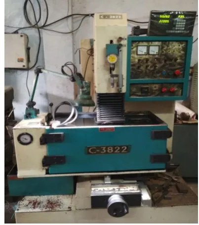
Machining was carried out in EDM of Electronic Electra plus C 3822 Die Sinking Machine. Machine is provided with fixed pulse voltage. The current, fluid pressure, pulse ON time and pulse OFF time were selected from the range. A Copper electrode of diameter 3 mm is used as cutting tool and the work piece of stainless steel is drilled and data to record the readings. Observations are taken in the form of mass of material removed per sec (gram/sec) for both work piece and brass electrode.
[image:2.595.331.533.531.759.2] [image:2.595.30.293.614.689.2]© 2018, IRJET | Impact Factor value: 6.171 | ISO 9001:2008 Certified Journal | Page 2739
2.3 Machining parameters and their levels
Table -3:Parameters and Their Levels for Machining
Control Parameters Levels
1 2 3
Pulse ON time (μs) A 8 10 12
Pulse OFF time (μs) B 2 3 4
Discharge Current(A) C 9 15 20
[image:3.595.310.551.72.341.2]Fluid Pressure(Kg/cm2) D 0.5 0.6 0.7
Table -4:Taguchi’s L9 OA
Exp. No. Pulse on Time Pulse off Time Current Fluid Pressure
Unit (µ Sec) (µ Sec) (Amp) (Kg/cm2)
1 1 1 1 1
2 1 2 2 2
3 1 3 3 3
4 2 1 2 3
5 2 2 3 1
6 2 3 1 2
7 3 1 3 2
8 3 2 1 3
9 3 3 2 1
2.4 Calculation of MRR and EWR
Material Removing Rate (MRR)
The Material Removal Rate (MRR) was calculated using the formula given below
Electrode Wear Rate (EWR)
The Tool Wear Rate (TWR) was calculated using the formula given below
2.5 Signal-to-noise ratio
SN ratio for MRR Larger is better S/N = −10 log(Σ(1/Y2)/n) SN ratio for EWR Smaller is better S/N = −10 log(Σ(Y2)/n))
3. RESULT AND ANALYSIS
Table -5:Experimental result
Exp No Pulse on Time Pulse off
Time Current Fluid
Pressure gm/min M.R.R gm/min E.W.R
1 8 2 9 0.5 0.00938 0.000781
2 8 3 15 0.6 0.01897 0.001186
3 8 4 20 0.7 0.01903 0.000001
4 10 2 15 0.7 0.01050 0.001749
5 10 3 20 0.5 0.01255 0.000001
6 10 4 9 0.6 0.00639 0.000001
7 12 2 20 0.6 0.01519 0.000844
8 12 3 9 0.7 0.01249 0.000694
9 12 4 15 0.5 0.01191 0.000851
Table -6:S/N ratio data
Ex p. No .
Pulse
on Time off Time Pulse Current Fluid Pressur
e
S/N Ratio
(MRR) S/N Ratio (EWR)
1 8 2 9 0.5 -40.5559 62.14698
2 8 3 15 0.6 -34.4387 58.51831
3 8 4 20 0.7 -34.4112 120
4 10 2 15 0.7 -39.5762 55.1442
5 10 3 20 0.5 -38.0271 120
6 10 4 9 0.6 -43.89 120
7 12 2 20 0.6 -36.3688 61.47315
8 12 3 9 0.7 -38.0688 63.17281
9 12 4 15 0.5 -38.4818 61.40141
Table -7: S/N Ratio Table for MRR
LEVEL PULSE ON PULSE OFF CURRENT FLUID PRESSURE
1 -36.47 -38.83 -40.84 -39.02
2 -40.50 -36.84 -37.50 -38.23
3 -37.64 -38.93 -36.27 -37.35
DELTA 4.03 2.08 4.57 1.67
[image:3.595.44.281.117.422.2]RANK 2 3 1 4
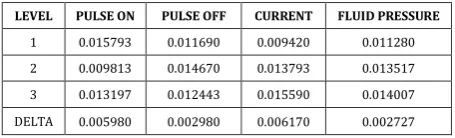
Table- 8: Response Mean Table for MRR
LEVEL PULSE ON PULSE OFF CURRENT FLUID PRESSURE
1 0.015793 0.011690 0.009420 0.011280
2 0.009813 0.014670 0.013793 0.013517
3 0.013197 0.012443 0.015590 0.014007
DELTA 0.005980 0.002980 0.006170 0.002727
Table - 9: S/N Ratio Table for EWR
LEVEL PULSE ON PULSE OFF CURRENT FLUID PRESSURE
1 -80.22 -59.59 -81.77 -81.18
2 -98.38 -80.56 -58.35 -80.00
3 -62.02 -100.47 -100.49 -79.44
DELTA 36.37 40.88 42.14 1.74
RANK 3 2 1 4
Table - 10: Response Mean Table for EWR
LEVEL PULSE ON PULSE OFF CURRENT FLUID PRESSURE
1 0.000656 0.001125 0.000492 0.000544
2 0.000584 0.000627 0.001262 0.000677
3 0.000796 0.000284 0.000282 0.000815
[image:3.595.321.549.481.550.2]© 2018, IRJET | Impact Factor value: 6.171 | ISO 9001:2008 Certified Journal | Page 2740
Table -11: Analysis of Variance of S/N ratio (MRR)
Source DF Seq SS Adj SS Adj MS PC
Pulse on Time 2 2986.23 2986.23 993.12 45.56
Pulse off Time 2 1201.45 1201.45 1250.72 18.33
Discharge Current 2 2068.05 2068.05 1334.02 31.55
Fluid Pressure 2 228.65 228.65 2.32 3.49
Residual Error 2 69.69 69.69 - 1.06
total 10 6554.07 6554.07 100.00
Chart -1: Mean of SN Ratio of MRR
Chart -2: Mean of Means of MRR
Chart -3: Mean of SN Ratio of EWR
Chart -4: Mean of Means of EWR
3. CONCLUSIONS
After completion of Experimental work data was optimize using Minitab 17.1. Optimize data is given as under:
This paper has presented an investigation on the optimization and the effect of machining parameters on MRR and EWR in EDMD operations. An optimum parameter combination for the maximum MRR and minimum EWR was obtained by using the signal-to-noise (S/N) ratio. The optimal levels of machining parameters of EDMD process were at level A1, B2, C3, D3 gives the maximum MRR. The optimal levels of machining parameters of EDMD process were at level A3, B1, C2, D3, gives the Minimum EWR
ANOVA shows that Pulse on time (A) has the maximum contribution i.e. 45.56% on MRR, Current (C) has 31.55% and Pulse off time (B) has 18 % contribution on MRR i.e. MRR is increase with increasing pulse on time up to a certain then decreasing, increasing in current MRR increase but after a certain limit increase in current MRR is decreased.
ACKNOWLEDGEMENT
I am thankful to collage management for cooperation during my study and thesis work. Also thankful to my research guide Prof. A S Verma for their moral support during the research work.
REFERENCES
[1] Venkata Rao “Advanced Modelling and Optimization of Manufacturing Processes” Springer. 2011.
[2] Harmanpreet, Manpreet Singh, Bipendeep “Optimization of EDM Process Parameters Using Taguchi Method: A Review” IJRET: International Journal of Research in Engineering and Technology eISSN: 2319-1163 | pISSN: 2321-7308 Volume: 04 Issue: 04 | Apr-2015
© 2018, IRJET | Impact Factor value: 6.171 | ISO 9001:2008 Certified Journal | Page 2741 [4] Choudhary, Sushil Kumar, “Current Advanced Research
Development of Electric Discharge Machining (EDM)”, International Journal of Research in Advent Technology, Vol.2, No.3, March 2014.
[5] Modi, T and Patel, Jignesh, “A review paper on Optimization of process parameter of EDM for air hardening tool steel”, Int. Journal of Engineering Research and Applications, ISSN: 2248-9622, Vol. 5, Issue 1(Part 1), January 2015, pp.32-37
[6] Raut G, “A Review on Optimization of Machining Parameters in EDM”. International Journal of Innovative Research in Science, Engineering and Technology, Vol. 4,pp 893-896. March 2015
[7] https://www.google.co.in/imgres?imgurl=https%3A%2
F%2Fimage.slidesharecdn.com