Vol. 08, Issue 12 (December. 2018), ||V (I) || PP 33-41
Practical Implementation Of UPQC Under Non-Linear Loading
Condition
Ragini Singh Thakur
1, Amrita Kranti Mishra
21Research scholar, Department of Electrical and Electronics Engineering, Trinity Institute of Technology &
Research, Bhopal, India 2
Associate Professor, Department of Electrical and Electronics Engineering, Trinity Institute of Technology & Research, Bhopal, India
Corresponding author;Ragini Singh Thakur
Abstract:
Non-linear load adversely affect the voltage stability of the distribution system. If not checked at time the generated harmonics may propagate further and can severely damage the supply system. Non-linearity of load generates harmonics which if not filtered out may damage the connected equipments. In this paper dual compensation based unified power quality conditioner has been proposed to rule out the harmonics of the system. The controller is designed using sinusoidal current as well as voltage source converter which take care of both voltage as well as current control. The steady state error is removed using PI controller.--- --- Date of Submission: 19-11-2018 Date of acceptance: 04-12-2018 ---
---I.
INTRODUCTION
control references, the dual compensating strategy uses only sinusoidal references to control the PWM converters.
II.
UNIFIED POWER QUALITY CONDITIONER (UPQC)
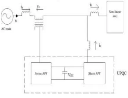
The main concern of power engineer is to maintain sinusoidal voltage and current at point of common coupling and also to supply harmonic free power to the consumer. The increased connectivity of non-linear loads had raised the demand of power conditioning devices. UPQC is one of the advance configurations of hybrid filter. In some literature it is also termed as universal filter [17].UPQC is a multifunction power conditioner employed to compensate voltage disturbances of the utility system, as a remedial for voltage fluctuation, and barricade the harmonic load current from entering the power system. It is designed by integrating series active filter and shunt active filter. The UPQC is accepted as one of the most powerful filter to large capacity loads sensitive to supply voltage flicker/imbalance. At the distribution side/ industrial load UPQC can improve power quality at the point of installation. Since last two decades it has been under research to improve voltage profile at distribution side. The state of the art of design of UPQC is to make the load equal to a resistance which done by inserting a series voltage proportional to the line current As the UPQC is a combination of series and shunt active filters, two active filters have different functions. The series active filter suppresses and isolates voltage-based distortions. The shunt active filter cancels current-based distortions. At the same time, it compensates reactive current of the load and improves power factor. The general configuration of UPQC is shown in Figure 1.
Figure 1 Schematic of UPQC
UPQC is crafted to protect the sensitive load at the point of installation connected to distorted distribution systems by correcting any of the following shortcomings:
harmonic distortions (of source voltage and load current) at the utility--consumer PCC,
voltage disturbances (sags, swells, flickers, imbalances, and instability),
voltage regulation,
reactive power flow at fundamental and harmonic frequencies,
neutral and negative-sequence currents, and
harmonic isolation (e.g., between a sub-transmission and a distribution system).
III. CONTROL STRATEGIES FOR UPQC
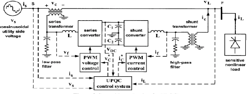
Shunt converter is a voltage-source converter connected in shunt with the same AC line and acts as a current source to cancel current distortions, to compensate reactive current of the load, and to improve the power factor. It also performs the DC-link voltage regulation reducing the rating of the DC capacitor. The output current of the shunt converter is adjusted (e.g., using a dynamic hysteresis band) by controlling the status of semiconductor switches such that output current follows the reference signal and remains in a predetermined hysteresis band.
Figure 2 Control Loop Design for UPQC
1) Control Loop Design;
The accurate compensation calculation and the reference for voltage unbalance factor can be accurately obtained by properly designing controller.
The function of the controller can be defined with the following blocks;
i) The PCC voltage control block is used to track the VUF reference with a PI controller.
ii) The negative sequence current sharing block is used to produce the weighting factor for the output of the PCC voltage control block.
iii) The feed forward block is used to improve the dynamic response when the VUF reference steps rapidly.
IV. PROPOSED WORK
In this paper the practical implementation of the UPQC connected to the three phase distribution system under various operating conditions is present. The work has been carried out in three parts;Firstly; modeling of UPQC in matlab using simulink toolbox is carried out. The parameters chosen are mentioned in table 1. For modeling two converters one connected in series working as voltage converter and another connected in parallel with the supply system acting as current controller is designed. The series APF is triggered by generating control signal with PI controller whose gains are given in table 1. Series converter references are extracted from supply voltage which is first transformed using parks transformation than PI controller generates the control signal which is again converted from dqo-abc reverse parks transformation. The shunt converter forces the feeder (system)current to become a balanced (harmonic-free) sinusoidal waveform, while the seri es converter ensuresa balanced, sinusoidal, and regulated load voltage.
Secondly; the modeled UPQC is connected in the three phase distribution system. Three types of non-linear loadingis connected to check the performance of the modeled UPQC. Also condition of voltage sag is created to analyze the system under emergency state. The results are presented in next section. The scope of the research is to eliminate current harmonics load side generated due to non-linear loading and voltage sag. To regulate the load voltage and prevent it propagating further hence to safeguard the voltage sensitive equipments.
Table 1 Simulation model parameters
Effective nominal voltage of the utility (line to neutral))
Vs a , b , c = 127 V
Nominal utility grid frequency fs = 50 Hz Series filter inductance and capacitance 11H, 28e-6H Inductance, resistance and Capacitances of the
parallel
13e-6H, 10 ohm, 50e-6F
Transformation ratio of the series coupling transformers
n = 1
dc-bus voltage Vd c = 400 V
Table 2 Various operating conditions
Unbalanced three phase loads Phase A Phase B Phase C
Three single phase rectifier with RL loading R=8.1 ohm L=380mH
R=10.12 ohm L=346mH
R=8.1 ohm L=357mH Three single phase rectifier with RLC loading R=13.5 ohm
C=940 micro F
R=10.12 ohm L=346mH
R=8.1 ohm L=380mH Balanced loading connected via three phase full
wave rectifier
R=17 ohm
Voltage sag Three phase fault with ground resistance 0.001ohm persisting for 0.3seconds
V.
Simulation results
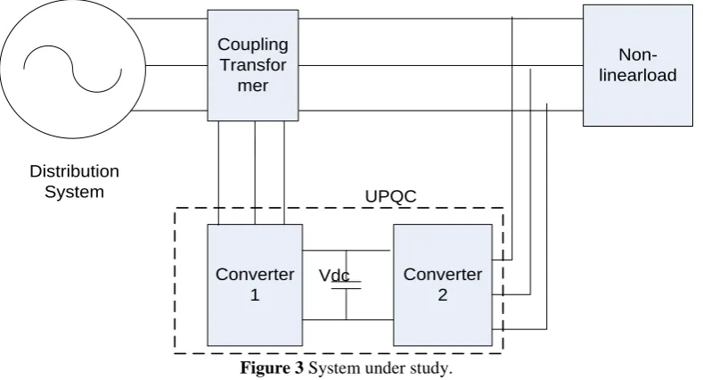
The system under study is shown in figure 3 which has been modeled in matlab simulink 2013a. For analyzing the performance of the system the three cases of operation of three phase three wire distribution system has been considered. The weak grid suffers from the problem of voltage unbalance which has been removed by designing controller which is placed between distribution system and the load terminal. The controller consists of two converter one controls the grid voltage unbalance and another stabilize the load current harmonics. The simulation results for system have been discussed below;
Case 1; non-linear load connected to distribution system without UPQC. Case 2; non-linear load connected to distribution system with UPQC.
Case 3; condition of voltage sag on distribution system without and with UPQC.
Non-linearload
Converter 2 Converter
1 Distribution
System
Vdc
UPQC Coupling
Transfor mer
Figure 3 System under study.
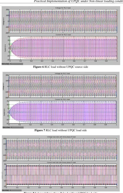
Distribution system performance under non-linear loading without UPQC
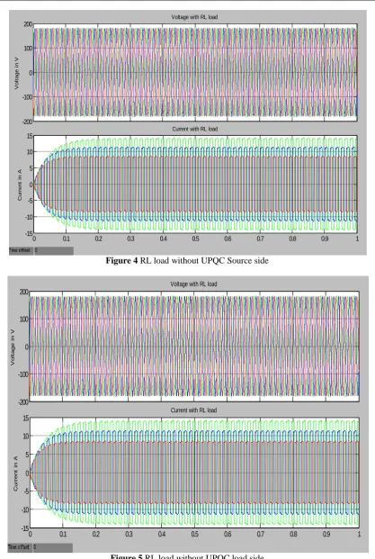
It can be seen from the figures 5-8 that though the source voltage is stable under non-linear loading but
source current is distorted a lot which may damage the other load or equipment connected to the same system. The harmonic content of the source and load current are mitigated to a very extent employing UPQC whose
results are presented in next section.
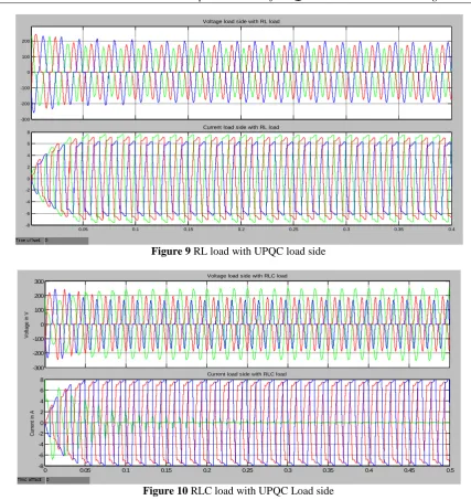
Distribution system performance under non-linear loading with UPQC
This section presents the distribution system performance with UPQC. All the three non-linear loading behavior with UPQC connected are presented in figures 9 and 10. The comparisons of THD percentage and the level of mitigation of harmonic both in source as well as load side is presented in tables 1and 2.
Voltage sag
Figure 4 RL load without UPQC Source side
Figure 5 RL load without UPQC load side
-200 -100 0 100 200
V
o
lt
a
g
e
i
n
V
Voltage with RL load
0 0.1 0.2 0.3 0.4 0.5 0.6 0.7 0.8 0.9 1
-15 -10 -5 0 5 10 15
C
u
rr
e
n
t
in
A
Current with RL load
-200 -100 0 100 200
V
o
lt
a
g
e
i
n
V
Voltage with RL load
0 0.1 0.2 0.3 0.4 0.5 0.6 0.7 0.8 0.9 1
-15 -10 -5 0 5 10 15
C
u
rr
e
n
t
in
A
Figure 6 RLC load without UPQC source side
Figure 7 RLC load without UPQC load side
Figure 8 balanced three phase R load without UPQC load side
-200 -100 0 100 200 V ol ta ge in V
Voltage for RLC load
0 0.1 0.2 0.3 0.4 0.5 0.6 0.7 0.8 0.9 1
-15 -10 -5 0 5 10 15 C ur re nt in A
Current for RLC load
-200 -100 0 100 200 V ol ta ge in V
Voltage for RLC load
0 0.1 0.2 0.3 0.4 0.5 0.6 0.7 0.8 0.9 1
-15 -10 -5 0 5 10 15 C ur re nt in A
Current for RLC load
-200 -100 0 100 200 V o lt a g e i n V
Voltage load side with three phase R load
0 0.1 0.2 0.3 0.4 0.5 0.6 0.7 0.8 0.9 1
-20 -10 0 10 20 c u rr e n t in A
Figure 9 RL load with UPQC load side
Figure 10 RLC load with UPQC Load side
Table 4 Comparison of Load Current THD with and without UPQC
Loading condition Phase A Phase B Phase C
Phase A Phase B Phase C
Without UPQC With UPQC Three single-phase
full-wave rectifiers (unbalanced load 1)
51 40 55 41 30 34
Three single-phase full-wave rectifiers (unbalanced load 2)
46 40 57 21 23 25
Balanced three-phase load(17.7 ohm)
Three-phase full-wave Rectifier
28 28 28 24 24 24
-300 -200 -100 0 100 200
Voltage load side with RL load
0.05 0.1 0.15 0.2 0.25 0.3 0.35 0.4
-8 -6 -4 -2 0 2 4 6
8 Current load side with RL load
-300 -200 -100 0 100 200 300
V
ol
ta
ge
in
V
Voltage load side with RLC load
0 0.05 0.1 0.15 0.2 0.25 0.3 0.35 0.4 0.45 0.5
-8 -6 -4 -2 0 2 4 6 8
C
ur
re
nt
in
A
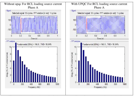
Without upqc For RCL loading source current Phase A
With UPQC For RCL loading source current Phase A
Figure 11 comparison of THD for fundamental waveform of source current for RCL loading
VI.
CONCLUSION
A flexible compensation strategy for distribution system under various balanced and unbalanced non-linear loading as well as for the condition of voltage sag is presented in this paper. The proposed dual compensatory UPQC topology successfully mitigates the load current harmonics and protects the supply system from voltage flickers. With the help of series and parallel active filters input and output currents are balanced, and regulated. The system has been analyzed under various nonlinear loading conditions. Also the behavior of the proposed UPQC custom power device is studied under the condition of voltage dip.
REFERENCES
[1]. Vinod Khadkikar, Member, IEEE, and Ambrish Chandra “UPQC-S: A Novel Concept of Simultaneous Voltage Sag/Swell and Load Reactive Power Compensations Utilizing Series Inverter of UPQC”. IEEE Transactions On Power Electronics, Vol. 26, NO. 9, SEPTEMBER 2011.
[2]. Vinod Khadkikar “Enhancing Electric Power Quality Using UPQC: A Comprehensive Overview”. IEEE Transactions On Power Electronics, VOL. 27, NO. 5, MAY 2012.
[3]. D. C. Bhonsle, R. B. Kelkar, “Design and Simulation of Single Phase Shunt Active Power Filter”, 2011 International Conference on Recent Advancements in Electrical, Electronics and Control Engineering. [4]. Mahesh Singh and Vaibhav Tiwari, “Modeling analysis and solution of Power Quality Problems”,
http://eeeic.org/proc/papers/50.pdf.
[5]. R.N.Bhargavi, “Power Quality Improvement Using Interline Unified Power Quality Conditioner”, 10th International Conference on Environment and Electrical Engineering (EEEIC), Page(s): 1 - 5, 2011. [6]. K. Palanisamy, J Sukumar Mishra, I. Jacob Raglend and D. P. Kothari, “Instantaneous Power Theory
Based Unified Power Quality Conditioner (UPQC)”, 25th Annual IEEE Conference on Applied Power Electronics Conference and Exposition (APEC), Page(s): 374 – 379, 2010.
[7]. G. Siva Kumar, P. HarshaVardhana and B. Kalyan Kumar, “Minimization of VA Loading of Unified Power Quality Conditioner (UPQC)”, Conference on POWERENG 2009 Lisbon, Portugal, Page(s): 552 - 557, 2009.
[8]. Rodrigo Augusto Modesto, S´ergio Augusto Oliveira da Silva, Azauri Albano de Oliveira, and Vin´ıciusD´ario Bacon, “A Versatile Unified Power Quality Conditioner Applied to Three-Phase Four-Wire Distribution Systems Using a Dual Control Strategy”, IEEE Transactions On Power Electronics, Vol. 31, No. 8, August 2016 5503.
[10]. T. A. Short, “Distribution Reliability and Power Quality”, Taylor & Francis Group, CRC Press, 2006, June 2009.
[11]. MojtabaNemati, HesamAddinYousefian and RouhollahAfshari, “Recognize the Role of DVR in Power Systems”, International Journal of Recent Trends in Engineering, Vol. 2, Page(s): 13 - 15, November 2009.
[12]. J. Barros, M. de Apraiz, and R. I. Diego, “Measurement of Subharmonics In Power Voltages”, Power Tech, IEEE Lausanne, Page(s): 1736 – 1740, 2007.
[13]. Mahesh Singh and Vaibhav Tiwari, “Modeling analysis and solution of Power Quality Problems”, http://eeeic.org/proc/papers/50.pdf.
[14]. ChellaliBenachaiba and BrahimFerdi, “Voltage Quality Improvement Using DVR”, Electrical Power Quality and Utilisation, Journal Vol. XIV, No. 1, 2008.
[15]. R.N.Bhargavi, “Power Quality Improvement Using Interline Unified Power Quality Conditioner”, 10th International Conference on Environment and Electrical Engineering (EEEIC), Page(s): 1 - 5, 2011. [16]. K. Palanisamy, J Sukumar Mishra, I. Jacob Raglend and D. P. Kothari, “Instantaneous Power Theory
Based Unified Power Quality Conditioner (UPQC)”, 25th Annual IEEE Conference on Applied Power Electronics Conference and Exposition (APEC), Page(s): 374 – 379, 2010.