Experimental and Finite Element Analysis of Fibre
Metal Laminates (FML’S) Subjected to Tensile,
Flexural and Impact Loadings with Different
Stacking Sequence
1
P.Sathyaseelan,
2K.Logesh,
3M.Venkatasudhahar,
4N.Dilip Raja
1,3,4Research Scholar, Department of Mechanical Engineering, Vel Tech University, Chennai, Tamil Nadu, India
2Assistant Professor, Department of Mechanical Engineering, Vel Tech University, Chennai, Tamil Nadu, India 1[email protected],2[email protected],3[email protected],4
Abstract-- The main objective of this research paper is
to study the mechanical behavior of Carbon Reinforced Aluminium Laminates (CARALL) under tensile, flexural and impact loads. It is a Fiber Metal Laminate (FML) which consists of layers of carbon fiber and thin layers of aluminium sheet bonded by epoxy resin. FML has a wide range of applications in Aerospace, Automotive, marine industries and it is also used in making of Sports goods due to their good strength. In this study, the tensile, flexural and impact performances of Carbon Reinforced Aluminium Laminates (CARALL) was investigated by experimental and finite element analysis. The FML is fabricated by hand layup method and then compressed using compression molding machine .The tensile strength, flexural strength and impact toughness of the laminates for two different stacking orders for each test was carried out as per the ASTM standards. The effect of stacking sequence with alternate layer of metal and carbon fiber is investigated experimentally and finite element analysis (FEA) is done. The results were compared. The experimental results were found to be closely equivalent with the FEA results that were performed.
Index Term-- FML, Tensile test, flexural strength, impact test,
FE-Analysis.
1. INTRODUCTION
Composite materials gained its interest during the past few decades after the successful use of these materials in applications of Military aircrafts during the Second World War [1]. Fiber Metal Laminates (FML) consists of alternately stacked layers of sheet metal and fiber reinforced polymers. Aramid reinforced Aluminium laminate (ARALL) was the first Fiber Metal Laminate developed by Aerospace Department of Delft University of Technology Netherlands during the year 1978 and it was made Commercially available in 1982[2, 3, 4].When metals and fibers are used separately they had certain advantages and drawbacks. For example an alloy of Aluminium has low fatigue strength; similarly carbon fiber also has low impact strength. When the two materials were combined together the advantages of material is increased reducing their own drawbacks [5]. The combination of fiber and metal is also used to overcome the characteristics like corrosion, bearing strength, impact resistance and the repair ability of the composite materials [6, 7]. Hence the material has the property and characteristics of both the metal and composite[8-10] .The Metal sheets and fibers are bonded together generally using adhesives like epoxy resin; the adhesion between the metal and fiber determine the
mechanical properties of the composite materials. Epoxies are used to reduce the rate of fatigue crack growth and also reduce the growth of cracks in the fractured sheets by acting as a crack barrier [11].
The Fiber reinforced metal laminates have high strength, fatigue resistance and specific stiffness and it is easy to manufacture for specific applications [12].The weight saving realized by fabricating components in aerospace industries, construction field and manufacturing of automotive and marine components.FML are used as a flat skins, and for lining the floors in cargo bay and the fuselage of A340 and other structural components in aircraft[13].The strength and stiffness of the FML can be varied by changing the stacking sequence of the metal and fiber in the composite materials [12, 14-21].
Carbon reinforced Aluminium Laminate (CARALL) has alternating layers of aluminium sheets and carbon fibers bonded with epoxy resin. The high stiffness of CARALL reduces the crack growth rates. CARALL is manufactured by hand lay-up method ,the surface of the aluminium sheet is treated for better bonding strength between the fiber and metal surface then it is allowed for natural curing followed by hot press curing [22, 23]The fabricating work is done with six different combinations of stacking sequence with (00, 90 0 and ± 450) orientation. This paper deals with fabrication and experimental investigation of different orientation of carbon fiber reinforced with aluminium alloy to improve the mechanical properties of the fiber metal laminate.
2. MATERIALS AND MANUFACTURING METHODOLOGY
The present work focuses on the fabricating techniques of Fiber Metal Laminate (FML) which deals with Carbon Reinforced Aluminium Laminate (CARALL).The influence of stacking sequence with respect to Aluminium, carbon fiber is discussed in detail in the following sections [24].
2.1. CARALL Preparation
scrubbed with emery paper to remove the smoothness of the surface which enables good bonding between the aluminium sheet and carbon fiber.
2.2. Stacking Sequence of CARALL
The CARALL is fabricated using different stacking sequence as per ASTM standards for tensile, flexural and impact test. The CARALL specimen of stacking order 1 & 2 is considered for tensile test and the specimen of stacking sequence 3 & 4 with Carbon fiber as top and bottom layer of the laminate is subjected to flexural test. The specimen of stacking sequence 5 & 6 with quasi- isotropic arrangement is taken for Impact Test [24].
The carbon fiber and aluminium sheets were arranged as per the stacking sequence.
(Stacking Order 1) – (Al/Ca00 /Al/ Ca00 / Ca900 /Al/ Ca00 /Al),
(Stacking Order 2) – (Al/Ca00 /Al/ Ca00 / Ca900 /Al/ Ca900 ), (Stacking Order 3) – (Ca00 /Al/ Ca00 / Ca00 / Ca900 / Ca00 /Al/
Ca00 ),
(Stacking Order 4) – (Ca00 /Al/ Ca00 /Al/ Ca00 / Ca900 /Al/ Ca00
/Al/ Ca00 ),
(Stacking Order 5) – (Ca0 0
/Al/ Ca90 0
/Al/ Ca0 0
/ Ca90 0
/Al/ Ca90 0
/ Al/ Ca00 /Al/ Ca900 / Al/ Ca00 /Ca900 /Al/ Ca900 /Al),
(Stacking Order 6) – (Ca00 /Al/ Ca450 /Al/ Ca00 / Ca900/Al/ Ca - 450 / Al/ Ca00 /Al/ Ca450 / Al/ Ca00 /Ca900 /Al/ Ca-450 /Al) .
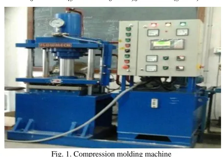
Fig. 1. Compression molding machine
(Image Courtesy- Engineering Design Division .CEG, Anna University, Chennai-25).
After the fabrication of the specimen by hand layup method, it is cured naturally for four hours and then it is hot cured by using compression molding machine (fig.1) at a temperature of 700C at a pressure of 70 bar for 10 minutes duration and the FML is cut in required dimension as per the ASTM standards for Mechanical Testing.
3. EXPERIMENTATION
3.1. Tensile Test
Tensile testing of the specimens with stacking order 1 and 2 is carried out as per ASTM D3039 Standard by using the Instron Universal Testing Machine which has a maximum capacity of 50 KN. The Test specimen was positioned vertically in the grips of the upper and lower jaws of the UTM.
The testing speed of the cross head is fixed as 1.27mm/min.A computer connected with the testing machine was utilized. The breaking load for each specimen is recorded by the computer system attached with the Universal testing machine.
Fig. 2. Tensile test- specimen before failure
Fig. 3. Tensile test- specimen after failure
The Fig.2. Shows the tensile testing of the laminate and the elongation of the specimen was continued until rupture was observed Fig.3. The load value at break was also recorded.
3.2. Flexural Test
Flexural testing is an important part of the characterization process of any material because the test result provides relevant information for how the materials will behave under real – world conditions. Flexural testing is carried out by three point bending method as per ASTM D 790 standard by using universal testing machine (UTM) that was used to perform the tensile tests on the specimens and corresponding Load Vs Displacement curve is obtained. The ultimate breaking load is obtained from the graph and by using the formula the flexural stress is calculated.
Flexural stress, σ = 3PL / 2bd² Flexural Modulus =L3m/4bd3
Fig. 4. Flexural test setup in universal testing machine
Fig. 5. Flexural test -specimen after failure
Fig.4 shows the flexural test of the specimen by three point bending method, where the load is applied at the mid span the specimen and the corresponding values are recorded. The failure of the specimen after flexural test is shown in the Fig.5.
3.3. Impact Test
Impact tests are designed to measure the resistance to failure of a material to a suddenly applied force such as collision, falling object or instantaneous blow. Material toughness is the ability of a material to absorb energy during plastic deformation. Izod impact testing is an ASTM D 7136 standard method of determining impact energy. The specimens are cut into required dimension as per standards and tested. The Izod test is most commonly used to evaluate the relative toughness or impact toughness of materials and as such is often used in quality control applications where it is a fast and inexpensive test. It is not a definite test it is just used as a comparison test. Izod test sample usually have a V-notch engrave into the specimen, sometimes specimens without notch also used.
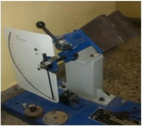
Fig. 6. Impact test -specimen loaded in the Impact Tester
A pendulum with adjustable weight is released from a known height. A rounded point on the tip of the pendulum makes contact with the specimen. The impact strength of the specimen is obtained directly from the reading scale in the impact tester.
4. FINITE ELEMENT ANALYSES USING ANSYS
Finite element analysis of Carbon Reinforced Aluminium Laminate is done using ANSYS ©10 software. The input data is given to loading and meshing of the laminate. The laminate is considered to be fixed at one end and corresponding tensile load to be given at another end. The laminate displacement in all x, y, and z direction has to be fixed, corresponding ultimate load to the laminate as to be given at another end and the results are obtained.
Fig. 8. Finite Element Analysis of flexural specimenwith stacking order3 using ANSYS software
The tensile stress of the specimen with stacking order 1 is 209 Mpa Fig.7. Stacking order 2 has a tensile stress of 245.719 Mpa. Similarly the Flexural stress of the specimen with stacking order 3 is 214.59 Mpa Fig.8. Stacking order 4 has a flexural stress of 164.77 Mpa. The FE-Analysis is compared with experimental values and their deviation is tabulated in Table I & II.
5. RESULT AND DISCUSSION
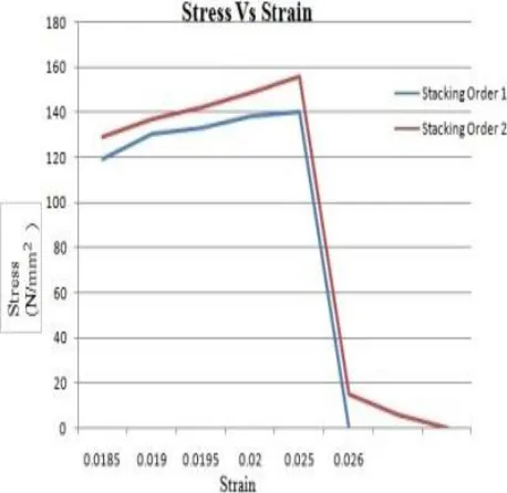
Fig. 9. Stress Vs Strain Graph for Stacking order 1 &2
Fig.9. Shows the Stress-Strain value of laminates with stacking order 1 & 2 and it is found from the experimental result that stacking order 1 has a tensile stress of 191.12 Mpa and stacking order 2 has tensile stress 228.98 Mpa. The tensile stress value of Stacking order 2 is greater than stacking order 1 and the FE- Analysis values for the
tensile stress of stacking order 2 is 245.7 Mpa which is greater than the stacking order 1 value of 209 Mpa.
Fig. 10. Load Vs Displacement Graph for Stacking order 3 &4
Table I
Comparison of Experiment and FEA value of tensile stress
Similarly flexural stress is calculated experimentally for stacking order 3 & 4 is found to be 236.53 Mpa for stacking order 3 and for stacking order 4 it is found to be 146.45 Mpa. The FEA values are 214.59 Mpa and 164.77 Mpa for stacking order 3&4.
Table II
Comparison of Experiment and FEA value of Flexural Stress
Impact Toughness for stacking order 5 & 6 is found out to be 24.34 x 10⁻⁴ J/mm3 and 27.68 x 10⁻⁴ J/mm3..Further the experimental and FE-A results were compared (Table 1 & 2) and it has a minimum deviation of 6.81 % and maximum deviation of 8.6% for tensile stress. Similarly the flexural
Flexural stress
(Mpa) Stacking order 3 Stacking order 4
Experiment 236.53 146.45
Finite Element
Analysis 214.59 164.77
% Deviation 10.2 10.7
Tensile stress
(Mpa) Stacking order 1 Stacking order 2
Experiment 191.12 228.983
Finite Element
Analysis 209 245.719
stress has a minimum deviation of 10.2% and maximum deviation of 10.7% with that of the experimental result.
6. CONCLUSION
The CARALL laminates were prepared and they were tested experimentally with two different stacking orders. It has been observed from result that the tensile strength of the laminate increases with thickness of the laminate. The FML with stacking order 2 has more tensile stress than stacking order 1.The top layer and bottom layer of the specimen is made up of aluminium. This increases the strength of the composite and delays the rupture of the specimens. Flexure and impact test were also carried out for two different stacking orders for each test. The experimental results of the tensile test and flexure test were compared using ANSYS software and it found that for the tensile testing, experimental results matches with the numerical results with a maximum deviation of 8.6 % and that for that of the flexure test, has a maximum deviation of 10.7 %. The sequence of failure of CARALL is cracking of the matrix material, followed by Aluminium sheet metal and epoxy de-bonding and finally carbon fiber breakage.
REFERENCE
[1] Botelho EC, Silva RA, Pardini LC, Rezende MC. A review on the development and properties of continuous fiber/epoxy/aluminum hybrid composites for aircraft structures. Mater Res 2006; 9(3):247–56.
[2] Villanueva GR, Cantwell WJ. The high velocity impact response of composite and FML-reinforced sandwich structures. Composites Science Technology 2004; 64:35–54.
[3] Sun CT, Dicken A, Wut HF. Characterization of impact damage in ARALL laminates. Composites Science Technology 1993; 49:139–44.
[4] Lee SM, editor. Handbook of composite reinforcements. Wiley VCH Publishers Inc.; 1993. pp. 1–6.
[5] Vogelesang LB, Vlot A. Development of fibre metal laminates for advanced. J Mater Process Technology 2000; 103:1–5.
[6] Alderliesten RC, Benedictus R. Fiber/metal composite technology for future primary aircraft structures. In: 48th Aiaa/Asme/Asce/Ahs/Asc structures, structural dynamics, and materials conference 15th; April 23–26, 2007;Honolulu, Hawaii; 2007. P. 1–12.
[7] Chang PY, Yeh PC, Yang JM. Fatigue crack initiation in hybrid boron/glass/aluminum fiber metal laminates. Mater Sci Eng 2008; A 496:273–80.
[8] Vlot A. Impact properties of fibre metal laminates. Compos Eng 1993; 3(10):911–27.
[9] E.C. Botelho, R.S. Almeida, L.C. Pardini and M.C.Rezende: Int. J. Eng. Sci., 2007, 45, 163.
[10] G. Reyes and H. Kang: J. Mater. Proc. Technol.,2007, 186, 284. [11] Asundi A, Choi Alta YN. Fiber metal laminates: an advanced
material for future aircraft. J Mater Process Technol 1997; 63:384– 94.Honolulu, Hawaii; 2007. p. 1–12.
[12] Reyes VG, Cantwell WJ. The mechanical properties of fibre-metal laminates based on glass fibre reinforced polypropylene. Compos Sci Technol 2000;60:1085–94.
[13] Vogelesang LB, Vlot A. Development of fibre metal laminates for advanced aerospace structures. J Mater Process Technol 2000;103(1–5).
[14] Xia Y, Wang Y, Zhou Y, Jeelani S. Effect of strain rate on tensile behavior of carbon fiber reinforced aluminum laminates. Mater Lett 2007;61:213–5.
[15] Hull, D., An Introduction to Composite Materials, Cambridge University Press, Cambridge, (1992), 1-57.
[16] Kim, J. K.; Sham, M. L., Impact and Delamination Failure of Woven Fabric Composites, Composites Science and Technology, 60 (2000), 745–761.
[17] Kacir, L.; Narkis, M.; Ishai, O., Oriented Short Glass-Fiber Composites: 1. Preparation and StatisticalAnalysis of Aligned Fiber Materials, Polymer Engineering Science, 15 (1975), 525-531.
[18] Dhakal, H. N.; Zhang, Z. Y.; Richardson, M. O. W.,Effect of Water Absorption on the Mechanical Properties of Hemp Fibre Reinforced Unsaturated Polyester Composites, Composites Science Technology, 67 (2007), 1674-1683.
[19] Johnson WS, Hammond MW. Crack growth behavior of internal titanium plies of a fiber metal laminate. Composites Part A 2008; 39:1705–15.
[20] Wang, W.; Sain, M.; Cooper, P. A., Study of Moisture Absorption in Natural Fibre Composites, Composites Science Technology, 66 (2006), 379–386.
[21] Mishra, S.; Mohanty, A. K.; Drzal, L. T.; Misra. M.;Parija, S.; Nayak, S. K.; Tripathy, S. S., Studies on Mechanical Performance of Biofibre/Glass Reinforced Polyester Hybrid Composites, Composite Science Technology, 63 (2003), 1377-1385.
[22] A review: Fibre metal laminates, background, bonding types and applied test methods, Tamer Sinmazcelik, Egemen Avcu, Mustafa Ozgur Bora , Onur Coban, Materials and Design 32 (2011) 3671– 3685.
[23] Lin CT, Kao PW, Yang FS. Fatigue behavior of carbon fibre-reinforced aluminium laminates. Composites 1991; 22(2):135–41. [24] M.Vasumathi, Vela Murali, Effect of alternate metals for use in