IJSRSET1841130 | Received : 12 January 2018 | Accepted : 29 January 2018 | January-February-2018 [(4) 1 : 541-550]
© 2018 IJSRSET | Volume 4 | Issue 1 | Print ISSN: 2395-1990 | Online ISSN : 2394-4099 Themed Section : Engineering and Technology
541
Design and Analysis of a Random Number Generator on FPGA
D. S. Bhojane1,Sneha S. Oak2 , Vishakha V. Bonde3
1Assistant Professor, Electronics and Telecommunication Engineering, DMIETR, Wardha, Maharashtra, India 2Assistant Professor, Electronics and Telecommunication Engineering, DMIETR, Wardha, Maharashtra, India
3Lecturer, Electronics and Telecommunication Engineering, VSPD, Amravati, Maharashtra, India
ABSTRACT
Random numbers are used in a wide variety of applications. True random number generators are slow and expensive for many applications while pseudo random number generators (RNG) suffice for most applications. Although a majority of random number generators have been implemented in software level, increasing demand exists for hardware implementation due to the advent of faster and high density Field Programmable Gate Arrays (FPGA). FPGAs make it possible to implement complex systems, such as numerical calculations, genetic programs, simulation algorithms etc., at hardware level. This paper discusses in detail the hardware implementation of several RNGs and their characteristics. Random number generator is required extensively by many applications like cryptography, simulation, numerical analysis, text-to-speech etc. Most C libraries have a pair of library routines for initializing, and then generating random numbers. For parametric speech synthesis application, a random number generator is required to produce noise samples. Therefore, a need has been felt for the design of a dedicated hardware for random number generator that generates one random number per cycle so that text-to speech conversion is done in real time.
Keywords: Random Number Generator, Cryptography, C, synthesis, text-to-speech, FPGA
I.
INTRODUCTION
Random numbers are widely used in various applications such as Monte Carlo simulations, cryptography, simulations of wireless communication systems, electronic circuit testing, genetic programming, data encryption, games etc. Usually, random numbers are generated using software algorithms. Although the sequence of numbers they produce seems random, they are not truly random. It is difficult to program a series of logical steps that produce numbers that do not follow some definite sequence. These random numbers are called Pseudo random numbers. True random numbers can be generated from a physical process, such as measuring thermal noise or noise power level in a radio-frequency receiver, photoelectric effect or other quantum phenomena. These processes are, in theory, completely unpredictable. True random number
The 8 and 16 bit length sequence using verilog HDL implemented on FPGA kit. Also the comparison between 8and 16 bits on the basis of synthesis and simulation result. FPGA can implement any logical expression i.e. it is predefined reconfigurable IC. It can be reconfigured any number of time. Therefore FPGA kit is used for rapid prototype development as compared to ASIC; hence FPGA is used to implement design. There are two main approaches to generating random numbers using a computer: Pseudo- Random Number Generators (PRNGs) and True Random Number Generators (TRNGs). The approaches have quite different characteristics and each has its pros and cons.
II.
LITERATURE REVIEW
From the rigorous review of related work and published literature, it is observed that many researchers have designed random number generation by applying different techniques. Researchers have undertaken different systems, processes or phenomena with regard to design and analyze RNG content and attempted to find the unknown parameters. A pseudorandom number generator (PRNG),is an algorithm for generating a sequence of numbers that approximates the properties of random numbers. These sequences are not truly random. Although sequences that are closer to truly random can be generated using hardware random number generators, pseudorandom numbers are important in practice for simulations (e.g., of physical systems with the Monte Carlo method), and are important in the practice of cryptography.
Ray C. C. Cheung, Dong-U Lee, John D. Villasenor [1], presented an automated methodology for producing hardware-based random number generator (RNG) designs for arbitrary distributions using the inverse cumulative distribution function (ICDF). The ICDF is evaluated via piecewise polynomial approximation with a hierarchical segmentation scheme that involves uniform segments and segments with size varying by powers of two which can adapt to local function nonlinearities. Analytical error
Leap-Ahead LFSR architecture has very good Area Time performance and Throughput performance that are 2.18×10- 9 slices×sec per bit and 17.87×109 bits per sec. Jonathan M. Comer, Juan C. Cerda, Chris D. Martinez, and David H. K. Hoe [3] introduced new architecture using Cellular Automata. Cellular Automata (CA) have been found to make good pseudo-random number generators (PRNGs), and these CA-based PRNGs are well suited for implementation on Field Programmable Gate Arrays (FPGAs). To improve the quality of the random numbers that are generated, the basic CA structure is enhanced in two ways. First, the addition of a super-rule to each CA cell is considered. The overviews of the design of linear feedback shift register (LFSRs) and cellular automata (CA), followed by a review of related works that have utilized LFSR and CA for generating random numbers. Therefore, evaluated the performance of CA-based PRNGs suitable for implementation on FPGAs. Synthesis results for the Xilinx Spartan 3E FPGA give a good idea of the relative resources required for each configuration. Pawel Dabal, Ryszard Pelka [4] presented ―FPGA Implementation of Chaotic Pseudo-Random Bit Generators‖ Modern communication systems (including mobile systems) require the use of advanced methods of information protection against unauthorized access. Therefore, one of the essential problems of modern cryptography is the generation of keys having relevant statistical properties. In recent years, the cryptographers pay an increasing attention to digital systems based on chaos theory. The use of chaotic signals to carry information .An idea of using a nonlinear chaotic dynamic system for design of cryptographic secure pseudo-random number or bit generator (PRNG or PRBG) seems to be interesting from practical reasons. Carlos Arturo Gayoso, C. González, L. Arnone, M. Rabini, Jorge Castiñeira Moreira, [5] presented ―Pseudorandom Number Generator Based on the Residue Number System and its FPGA Implementation‖ Residue Number System (RNS), which allows us to design a very fast circuit that has a very different way of operating with respect to other generators. A set of classic tests, the
Diehard test, the statistic complexity test and the Hurst exponent test are used to provide a measure of the quality of the randomness of the proposed pseudorandom number generator. David B. Thomas, Wayne Luk, [6] presented ―The LUT-SR Family of Uniform Random Number Generators for FPGA Architectures‖. A type of FPGA RNG called a LUT-SR RNG, which takes advantage of bitwise XOR operations and the ability to turn lookup tables (LUTs) into shift registers of varying lengths. This provides a good resource–quality balance compared to previous FPGA-optimized generators, between the previous high-resource high-period LUT-FIFO RNGs and low-resource low-quality LUTOPT RNGs, with quality comparable to the best software generators. The LUT-SR generators can also be expressed using a simple C++ algorithm contained within this paper, allowing 60 fully-specified LUT-SR RNGs with different characteristics to be embedded in this paper, backed up by an online set of very high speed integrated circuit hardware description language (VHDL) generators and test benches. Ravi Saini, Sanjay Singh, Anil K Saini, A S Mandal, Chandra Shekhar [7] presented ―Design of a Fast and Efficient Hardware Implementation of a Random Number Generator in FPGA‖ presents a fast and efficient hardware implementation of a pseudo-random number generator based on Lehmer linear congruential method. Demonstrated in this paper that how the introduction of application specificity in the architecture can deliver huge performance in terms of area and speed. The design has been specified in VHDL and is implemented on Xilinx FPGA device XC5VFX130T- 3ff1738 and takes up only 23 slice LUTS. In 2014, Purushottam Y. Chawle and R.V. Kshirsagar [8] , presented a simple algorithm to generate pseudo random number using Linear Feedback Shift register(LFSR).The generated pseudo sequence is mainly used for communication process such as cryptographic, encoder and decoder application in coded format.
designed using verilog HDL language to study their performance and randomness. LFSR is a shift register whose output random state is depend on feedback polynomial.
III.
ANALYSIS OF PROBLEM
In examining the quality of the samples, it is seen that the differences between the samples produced by the hardware and the corresponding samples that would be produced using an ICDF approximation with floating point accuracy. Bit-widths of signals are important parameters that designers can tweak to improve the quality of a design in terms of area, latency, and throughput. The goal is to use the minimal bit-widths to each signal, while respecting error constraints at the output. The Leap-Ahead architecture acquires much higher working frequency, while consumes much less slices. So, the Area Time performance of Leap-Ahead architecture is 2.18 slices×sec per bit, much better than the other ones.. Leap-Ahead architecture works slower than the Multi-LFSR architecture. This is because the feedback logic is much more complicated in the Leap-Ahead architecture. And the Fan- Out of each register is larger, too.
IV.
OBJECTIVES
1. To study the different algorithm about random number generator.
2. To study the hardware language platform VHDL.
3. To design and implement the various technique about Random number generation.
4. Verify the functionality of random number generation.
5. Analyze the design for FPGA device utilization summary, propagation delay and maximum operating frequency of design.
V.
PROPOSED WORK
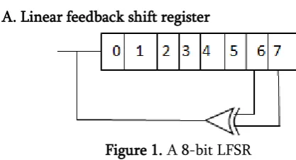
A. Linear feedback shift register
Figure 1. A 8-bit LFSR
The XOR gate provides feedback to the register that shifts bits from left to right. The maximal sequence consists of every possible state except the "00000000" state.
In computing, a linear-feedback shift register (LFSR) is a shift register whose input bit is a linear function of its previous state.
The most commonly used linear function of single bits is exclusive-or (XOR). Thus, an LFSR is most often a shift register whose input bit is driven by the XOR of some bits of the overall shift register value.
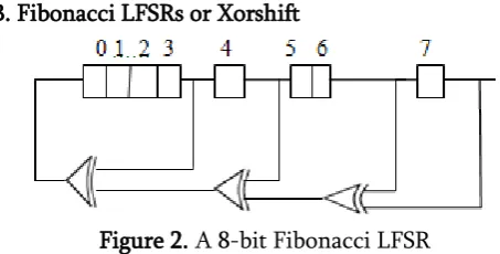
B. Fibonacci LFSRs or Xorshift
Figure 2. A 8-bit Fibonacci LFSR
The feedback tap numbers correspond to a primitive polynomial in the table so the register cycles through the maximum number of 256 states excluding the all-zeroes state. The bit positions that affect the next state are called the taps. In the diagram the taps are [7,6,4,3]. The rightmost bit of the LFSR is called the output bit. The taps are XOR'd sequentially with the output bit and then fed back into the leftmost bit. The sequence of bits in the rightmost position is called the output stream. The arrangement of taps for feedback in an LFSR can be expressed in finite field arithmetic as a polynomial mod 2. This means that the coefficients of the polynomial must be 1's or 0's. This is called the feedback polynomial or reciprocal characteristic polynomial. For example, if the taps are at the 7th, 6th, 4th and 3rd bits (as shown), the feedback polynomial is X7+X6+X4+X3+1 The 'one' in the polynomial does not correspond to a tap – it corresponds to the input to the first bit (i.e. x0, which is equivalent to 1). The powers of the terms represent the tapped bits, counting from the left. The first and last bits are always connected as an input and output tap respectively.
The LFSR is maximal-length if and only if the corresponding feedback polynomial is primitive. This means that the following conditions are necessary (but not sufficient):
The number of taps should be even.
The set of taps – taken all together, not pairwise (i.e. as pairs of elements) – must be relatively prime. In other words, there must be no divisor other than 1 common to all taps.
C. Galois LFSRs
Named after the French mathematician Évariste Galois, an LFSR in Galois configuration, which is also known as modular, internal XORs as well as one-to-many LFSR, is an alternate structure that can generate the same output stream as a conventional LFSR (but offset in time). In the Galois configuration, when the system is clocked, bits that are not taps are shifted one position to the right unchanged. The taps, on the other hand, are XOR'd with the output bit before they are stored in the next position. The new output bit is the next input bit. The effect of this is that when the output bit is zero all the bits in the register shift to the right unchanged, and the input bit becomes zero. When the output bit is one, the bits in the tap positions all flip (if they are 0, they become 1, and if they are 1, they become 0), and then the entire register is shifted to the right and the input bit becomes 1
Figure 3. A 8-bit Galois LFSR
To generate the same output stream, the order of the taps is the counterpart (see above) of the order for the conventional LFSR, otherwise the stream will be in reverse. Note that the internal state of the LFSR is not necessarily the same. The Galois register shown has the same output stream as the Fibonacci register in the first section. A time offset exists between the streams, so a different start point will be needed to get the same output each cycle.
In a software implementation of an LFSR, the Galois form is more efficient as the XOR operations can be implemented a word at a time: only the output bit must be examined individually.
D. Blum Blum Shub
Blum Blum Shub (B.B.S.) is a pseudorandom number generator proposed in 1986by Lenore Blum, Manuel Blum and Michael Shub (Blum et al., 1986).Blum Blum Shub takes the form: Xn+1 = Xn2mod n Where n=p x q is the product of two large primes p and q. At each step of the algorithm, some output is derived from xn+1; the output is commonly the bit parity of Xn+1 or one or more of the least significant bits of Xn+1. The two primes, p and q, should both be congruent to 3 (mod 4) .
Steps for executing Blum Blum Shub Generator algorithm:
The Blum Blum Shub Generator is known to be the cryptographically secure pseudo random number generator (CSPRNG). The algorithm for BBS generator is as follows:
Select two big prime numbers p and q, such that both the numbers leave a remainder of 3 when divided by 4.
Choose n = p * q
Choose seed s, such that s is relatively prime to n which means that neither p nor q is a factor of s.
Xo = s2 mod n
The consequent values are generated according to the formula Xi = (Xi1)2mod n
A sequence of binary digits is produced according to the formula Bi= Xi mod2
The output sequence is B1, B2, B3, B4…… Pipelining Introduction
a) Pipelining
Comes from the idea of a water pipe: continue sending water without waiting the water in the pipe to be out
leads to a reduction in the critical path
Either increases the clock speed (or sampling speed) or reduces the power consumption at same speed in a DSP system
b) Parallel Processing
Multiple outputs are computed in parallel in a clock period
The effective sampling speed is increased by the level of parallelism
Can also be used to reduce the power consumption water pipe
An instruction pipeline is a technique used in the design of computers to increase their instruction throughput (the number of instructions that can be executed in a unit of time). The basic instruction cycle is broken up into a series called a pipeline. Rather than processing each instruction sequentially (one at a time, finishing one instruction before starting the next), each instruction is split up into a sequence of steps so different steps can be executed concurrently (at the same time) and in parallel (by different circuitry). Pipelining increases instruction throughput by performing multiple operations at the same time (concurrently), but does not reduce instruction latency (the time to complete a single instruction from start to finish) as it still must go through all steps. Indeed, it may increase latency due to additional overhead from breaking the computation into separate steps and worse, the pipeline may stall (or even need to be flushed), further increasing latency. Pipelining thus increases throughput at the cost of latency, and is frequently used in CPUs, but avoided in real time systems, where latency is a hard constraint. Each instruction is split into a sequence of dependent steps. The first step is always to fetch the instruction from memory; the final step is usually writing the results of the instruction to processor Registers or to memory.
the assembly line is to keep each assembler productive at all times, pipelining seeks to keep every portion of the processor busy with some instruction. Pipelining lets the computer's cycle time be the time
of the slowest step, and ideally lets one instruction complete in every cycle.
VI.
RESULTS AND DISCUSSION
A. Simulation Result of LFSR
Figure 4. Simulation Result of LFSR Timing report without pipeline
1. Minimum period: 2.225ns (Maximum Frequency: 449.438MHz) 2. Minimum input arrival time before clock: 3.654ns
3. Maximum output required time after clock: 4.394ns
Timing report with pipeline
1. Minimum period: 2.213ns (Maximum Frequency: 451.875MHz) 2. Minimum input arrival time before clock: 4.054ns
3. Maximum output required time after clock: 4.283ns
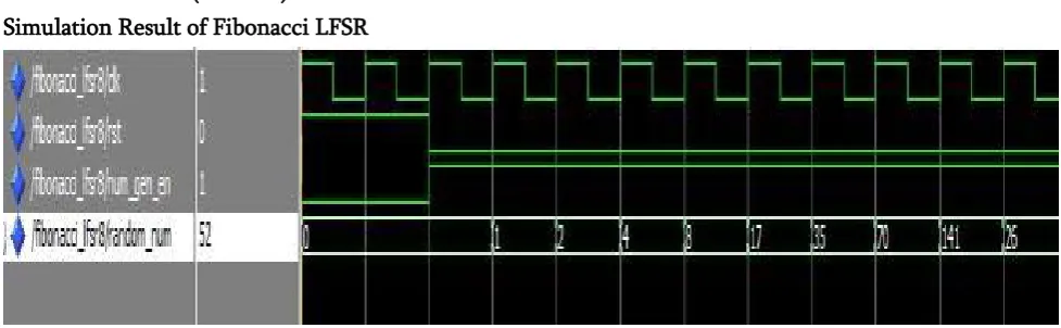
B. Fibonacci LFSR (Xorshift)
Simulation Result of Fibonacci LFSR
Figure 5. Simulation Result of Fibonacci LFSR
Timing report without pipelining
1. Minimum period: 3.455ns (Maximum Frequency: 289.436MHz) 2. Minimum input arrival time before clock: 4.229ns
Timing report with pipelining
1. Minimum period: 3.455ns (Maximum Frequency: 289.436MHz). 2. Minimum input arrival time before clock: 4.133ns
3. Maximum output required time after clock: 4.283ns
C. Galois LFSR
Simulation Result of Galois LFSR
Figure 6. Simulation Result of Galois LFSR Timing report without pipelining
1. Minimum period: 2.411ns (Maximum Frequency: 414.766MHz) 2. Minimum input arrival time before clock: 3.872ns
3. Maximum output required time after clock: 4.394ns
Timing report with pipelining
1. Minimum period: 2.411ns (Maximum Frequency: 414.766MHz) 2. Minimum input arrival time before clock: 3.776ns
3. Maximum output required time after clock: 4.394ns
D. Blum Blum Shub Simulation Result of BBS
Figure 7. Simulation Result of BBS
Timing report without pipelining 1. Minimum period: No path found
Timing report with pipelining
1. Minimum period: 46.666ns (Maximum Frequency: 21.429MHz) 2. Minimum input arrival time before clock: 50.584ns
3. Maximum output required time after clock: 4.571ns
Comparative analysis of Throughput parameter
Table 1
VII.
CONCLUSION
Several different ways have been already examined to increase randomness of random number generator. For a single bit random number generator, LFSR is most effective method. When multiple bits are required, LFSR can be extended by utilizing extra time and extra circuitry. Cryptographic algorithms and communication protocol are based on random number generation. By implementing, multi LFSR Architecture of both Fibonacci and Galois type on FPGA, we acquire conclusion that with only very little loss in speed, multi LFSR generate random number. For a good BBS generator with a long period time the seed x0 and the prime numbers P and Q must satisfy several requirements. Since this generator does not process any input, the unpredictability of the output is completely based on the unpredictability of the seed. If the seed is guessed once the whole output of the generator can be calculated. Due to this property, a reduced strength has a more severe impact than on entropy gathering or hybrid generators. The BBS generator does not process any input and can thus be applied when a reconstructible sequence of random numbers is desired like in the case of stream ciphers. By implementing pipelining, throughput of the various random number generation methods increases.
VIII.
APPLICATIONS
Random numbers have applications in many areas: simulation, game-playing, cryptography, statistical
sampling, evaluation of multiple integrals, particle transport calculations, and computations in statistical physics, to name a few. Since each application involves slightly different criteria for judging the ―worthiness‖ of the random numbers generated, a variety of generators have been developed, each with its own set of advantages and disadvantages.
IX.
REFERENCES
[1].Ray C. C. Cheung, John D. Villasenor, Wayne Luk, ―Hardware Generation of Arbitrary Random Number Distributions From Uniform Distribution Via the Inversion Method‖ vol.15, no. 8, August 2007.
[2].GU Xiao-chen, ZHANG Min-xuan ―Uniform Random Number Generator using Leap- Ahead LFSR Architecture‖2009 International Conference on Computer and Communications Security. [3].Jonathan M. Comer, Juan C. Cerda, Chris D.
Martinez, and David H. K. Hoe 44th IEEE Southeastern Symposium on System Theory University of North Florida, Jacksonville, FL March 11-13, 2012.
[4].Pawel Dabal, Ryszard Pelka ―FPGA Implementation of Chaotic Pseudo-Random Bit Generators‖ MIXDES 2012, 19th International Conference "Mixed Design of Integrated Circuits and Systems", May 24-26, 2012, Warsaw, Poland. [5].Carlos Arturo Gayoso, C. Gonzalez, L. Arnone, M.
Rabini, Jorge Castiñeira Moreira, ―Pseudorandom Number Generator Based on the Residue Number System and its FPGA Throughput LFSR Fibonacci LFSR Galois LFSR B.B.S
Without Pipeline 182×107 189.16×10⁷ 206.6×10⁷ 156.42×10⁷
Implementation‖ 2013 Argentine School of Micro-Nanoelectronics, Technology and Applications.
[6].David B. Thomas, Wayne Luk, ―The LUT-SR Family of Uniform Random Number Generators for FPGA Architectures‖ IEEE transactions on very large scale integration (VLSI) systems, vol. 21, no. 4, April 2013
[7].Ravi Saini, Sanjay Singh, Anil K Saini, A S Mandal, Chandra Shekhar ―Design of a Fast and Efficient Hardware Implementation of a Random Number Generator in FPGA‖ CSIR- Central Electronics Engineering Research Institute (CSIR-CEERI) Pilani- 333031, Rajasthan, India 2013 International Conference on Advanced Electronic Systems (ICAES).