IJEDR1802036
International Journal of Engineering Development and Research (
www.ijedr.org
)
203
Behavior of CFRP confined RC rectangular columns
with different aspect ratios
Abdelrahman Megahid Ahmed1, Omar Ahmed Farghal 2, Mohamed Ramadan Abdellatif3 1Professor, 2Associate Professor, 3 Assistant Lecturer
1civil engineering department
1Assiut Faculty of Engineering, Assiut, Egypt
_____________________________________________________________________________________________________
Abstract — In last decades, the use of externally fiber-reinforced polymer sheets (FRPs) has become increasingly popular for civil infrastructure applications. Early investigate studies have demonstrates that confinement enhancement of FRP wrapped circular columns is more efficient than that of square or rectangular RC columns. Most existing columns however, are square or rectangular in cross section. An experimental study has been carried out on rectangular RC columns strengthened with carbon fiber- reinforced polymer (CFRP) sheets. A total of 9 RC columns were loaded to failure in axial compression and examined in both axial and lateral directions. Number of wrap layers and aspect ratios were the main test parameters. Compression stress, axial and transverse strain have been registered to estimate the stress-strain relationships, ultimate strength and ductility of specimens. Results obviously indicate that CFRP wrapping can improve the structural performance of rectangular RC columns regarding both maximum strength and ductility. The effects of test parameters are evidenced and compared.
Index Terms—RC columns, CFRP, strength, ductility
_____________________________________________________________________________________________________
I.INTRODUCTION
IJEDR1802036
International Journal of Engineering Development and Research (
www.ijedr.org
)
204
II.EXPERIMENTAL PROGRAM
Specimen design
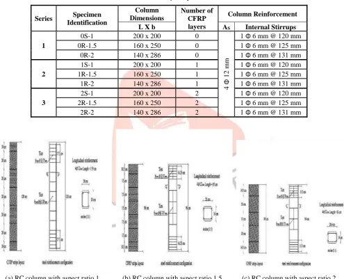
Nine rectangular RC columns were casted with 26 MPa concrete and deformed to achieve a slenderness ratio (H/b) equal to 6 to represent short columns and to avoid the formation of considerable secondary moment due to the slenderness effect, where H and b are the column’s height and the shorter side dimension of cross-section. All RC specimens have the same cross-section area with corner radius of 40 mm. The longitudinal steel ratio and transverse steel ratio were constant for all specimens and equal to 1.3%.and 0.4% respectively. The variables considered in this investigation include the aspect ratio L/b, where L is the longer side dimension of the cross-section and thickness of CFRP jacket. Aspect ratios 1, 1.5, and 2 were tested. The jacket thickness varied from non to one and two layer of CFRP with confinement ratio μf = 0.332 μf = 0.664 for one and two layer respectively, see
Figure.1 shows the cross-section of the test specimens and their steel configuration reinforcement.
The test specimens are summarized in Table 1. The specimens are labeled as XS (or R)-Y, where X is the number of CFRP layers, S stands for a square cross-section and R for a rectangular cross-section, and Y specifies the aspect ratio (H/b).
Table 1. Details of test specimens
Series Specimen
Identification
Column Dimensions
Number of CFRP layers
Column Reinforcement
L X b AS Internal Stirrups
1
0S-1 200 x 200 0
4
Φ
1
2
m
m
1 Φ 6 mm @ 120 mm
0R-1.5 160 x 250 0 1 Φ 6 mm @ 125 mm
0R-2 140 x 286 0 1 Φ 6 mm @ 131 mm
2
1S-1 200 x 200 1 1 Φ 6 mm @ 120 mm
1R-1.5 160 x 250 1 1 Φ 6 mm @ 125 mm
1R-2 140 x 286 1 1 Φ 6 mm @ 131 mm
3
2S-1 200 x 200 2 1 Φ 6 mm @ 120 mm
2R-1.5 160 x 250 2 1 Φ 6 mm @ 125 mm
2R-2 140 x 286 2 1 Φ 6 mm @ 131 mm
(a) RC column with aspect ratio 1 (b) RC column with aspect ratio 1.5 (c) RC column with aspect ratio 2 Figure 1. Configuration of internal reinforcement for the tested columns
Materials
Fine & coarse aggregate: angular crushed coarse aggregates were used in experimental work with maximum size of 20 mm.
River sand was as a fine aggregate. The properties of used aggregate are shown in Table 2.
Cement: ordinary Portland cement of 32.5 grade was used in the current experimental work. The test properties of Portland
cement are given in Table 3.
IJEDR1802036
International Journal of Engineering Development and Research (
www.ijedr.org
)
205
Table 2. Properties of fine and coarse aggregatesproperty gravel sand
Maximum nominal size 20 mm --
Fine modulus 6.2 2.56
Fine materials 0.6 1.6
Volume weight (t/m3) 1.67 1.68 Specific gravity 2.52 2.56 Crashing strength value 19.5 --
Water absorption (%) 0.7 1 Sulphate content (%) 0.003 0.012 Chloride content (%) 0.004 0.015
PH 7.5 8
Table 3. Properties of cement
Properties Results
Fineness of cement cm2/gm 2880 Compressive strength
kg/cm2
3 days 198 7 days 298
Setting Time
Initial 80 minute
Final 290
minute
soundness 5 mm
Steel: high tensile steel deformed steel bars of 12 mm diameter (with proof (yield) stress and ultimate tensile strength of 424 MPa
and 690 MPa, respectively) were used in all RC columns as longitudinal reinforcement; and 6 mm plain steel bars (with yield and ultimate strength of 302 MPa and 380 MPa respectively) were used as transverse reinforcement. See Table 4
CFRP sheets & epoxy resin: a high tensile strength carbon fiber Sika-wrap 300 was used for jacketing, and a two-part
sikadur-330 epoxy impregnation was used as adhesive. The CFRP materials had a nominal thickness of 0.166 mm. Details of materials properties of CFRP are presented in Table.5
Table 4. Properties of mild and high tensile steel
Steel type
Commercial diameter
(mm)
Yield or proof strength
(N/mm2)
Ultimate strength
(N/mm2)
Elongation %
M.S 6 302 380 0.26
H.T.S 12 424 690 0.126
Table 5. Properties of CFRP sheets
Weight
g/m2
Considering thickness (mm)
Tensile strength of fibers
(N/mm2)
Tensile modulus of fibers
(N/mm2)
230 0.166 3900 230000
Concrete mix proportions: the specimens were cast in specially manufactured steel moulds, by using concrete mix with average
compressive strength for three standard cubes (Fcu) of 26 MPa and corresponding concrete cylinder compressive strength (fcy) of 21 MPa after 28 days. the concrete mix proportions are shown in Table.6
Table 6. Concrete mix proportions
Concrete strength
N/mm2 Cement Sand Gravel Water
26 1 1.74 3.2 0.54
IJEDR1802036
International Journal of Engineering Development and Research (
www.ijedr.org
)
206
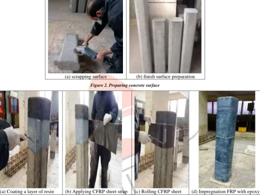
One day after casting, the specimens were removed from the moulds and cured with water at a constant temperature of 27 co for 28 days. After concrete columns were fully cured. The surface of the specimens was lightly sanded to remove surface contaminants, and was then cleaned with water and left to dry, see Figure 2. The two-part epoxy impregnation resin was then thoroughly mixed in according to manufacture’s specifications. Frist, the epoxy resin was directly applied onto the substrate, and then the fabric was carefully placed into resin with gloved hands and smooth out any irregularities or air pockets using a plastic laminating roller. The roller was continuously used until the resin was appeared on the surface of the fabric, as an indication of fully saturating. A second layer of resin was applied to allow the impregnation of CFRP. The second layer was applied in the same way. Finally, a layer of resin was applied to complete the operation as shown in Figure 3. Each layer was wrapped around the columns with an overlap of 150 mm to avoid sliding or deboning of fibers during tests. The wrapped specimens were left at room temperature for one week before testing.(a) scrapping surface (b) finish surface preparation Figure 2. Preparing concrete surface
(a) Coating a layer of resin (b) Applying CFRP sheet strap (c) Rolling CFRP sheet (d) Impregnation FRP with epoxy
Figure 3. CFRP application
Instrumentation
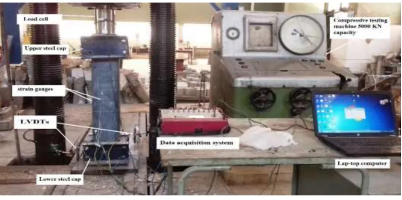
Four electrical strain gauges were attached to the surface of bonded CFRP sheets to measure the hoop strain at the column mid-height, and two linear variable displacement transducer (LVDT) was used to measure the average axial deformation of column through a gauge length equal to the column the column height. The LVDT used measured the upward movement of the lower rigid head of the testing Figure.4, so the measured deformations represented the average axial shortening of tested columns. Both the strain gauge and the LVDT were connected to a data acquisition system, which in turn was connected to a computer to regularly record all measurements. The load was measured by load cell placed above the specimens its capacity 2000 KN and was connected to a data acquisition system.
Testing
IJEDR1802036
International Journal of Engineering Development and Research (
www.ijedr.org
)
207
Figure 4. Details of test setupIII.TEST RESULTS AND DISCUSSION
Table.7 summarizes several response characteristics of the tested columns, including the maximum load (Pmax); the ratio (R)
of the maximum compressive strength of CFRP confined RC column (fcc) to their counterparts of the unconfined RC control columns (fco); and the mean axial strain ɛcc = ∆max/L, where ∆max is the measured axial shortening of tested columns at the ultimate load and L is the column height. In addition, it includes the transverse strains of the CFRP sheets ɛhz1 & ɛhz2 at long directions, which represent by average value ɛHZL and ɛhz3 & ɛhz4 at short directions, which represent by average value ɛHZS corresponding to the failure load and the failure modes of all columns.
Compressive strength and failure modes
It can be revealed that confinement with CFRP wrap increased the compressive strength. The greater the number of CFRP layers, the greater the gain in the compressive with respect to the corresponding unconfined column. For a given number of CFRP layers, the increase in aspect ratio resulted in a decrease in load capacity. The maximum increase were achieved in square columns, which showed a 34% and87.5% increase against the control columns for two-ply and one-ply CFRP confined columns respectively.
The typical failure modes of the confined columns are shown in Figure. 5, 6, and 7. Two modes of failure were observed during the experimental tests of RC columns. The first mechanism (FM1) was due to the crushing of concrete at either the middle third zone or the upper third zone as shown in Figure 5. the second failure mechanism (FM2) was observed for confined RC columns at either one-ply or two-ply CFRP due to rapture of CFRP sheet at the mid-height of specimen and it was accompanied with both a partial delamination of concrete cover and local concrete crushing, see Figure 6 and 7. During the loading, clicking sound could be heard, signifying the straining of CFRP sheet and the cracking of the epoxy resin. The final failure occurred suddenly with explosive sound.
Table 7. Experimental results of tested columns
Columns Pmax fco fcc R
Mean axial
strain ɛcc/ɛco
Horizontal strains Mode
of failure
Long direction Short direction
KN N/mm2 N/mm2 ɛ
cc (%) ɛhz1 ɛhz2 ɛHZL ɛhz3 ɛhz2 ɛHZS
0S-1 1152 29.5 -- 1 0.196 1 0.243 0.307 0.275 0.15 0.09 0.12 FM1
0R-1.5 1105 28.3 -- 1 0.188 1 0.33 0.29 0.31 0.05 0.119 0.0845 FM1
0R-2 936 24 -- 1 0.17 1 0.27 0.23 0.25 0.03 0.076 0.053 FM1
1S-1 1545 -- 39.6 1.34 0.411 2.10 0.9 0.996 0.948 0.75 0.986 0.868 FM2
1R-1.5 1452 -- 37.23 1.31 0.338 1.80 0.59 0.73 0.66 0.89 0.978 0.934 FM2
1R-2 1163 -- 29.82 1.24 0.284 1.67 0.48 0.46 0.47 0.8 0.72 0.76 FM2
2S-1 2160 -- 55.38 1.875 0.664 3.39 0.592 0.63 0.611 0.3 0.34 0.32 FM2
2R-1.5 1973 -- 50.6 1.785 0.552 2.94 0.48 0.542 0.511 0.85 0.91 0.88 FM2
IJEDR1802036
International Journal of Engineering Development and Research (
www.ijedr.org
)
208
(a) 0S-1 (b) 0R-1.5 (c) 0R-2
Figure 5. Failure mechanism (FM1) for unconfined RC columns
(a) 1S-1 (b) 1R-1.5 (c) 1R-2
Figure 6. Failure mechanism (FM2) for one-layer confined RC columns
(a) 2S-1 (b) 2R-1.5 (c) 2R-2
IJEDR1802036
International Journal of Engineering Development and Research (
www.ijedr.org
)
209
Stress-VL strain responseThe typical relationship between the applied axial stress and the corresponding axial strain of tested columns are presented in
Figures 8 and 9. The axial vertical strains are calculated from the average readings of the two vertical LVDTs divided by the
gauge length, which represent the column’s height. An examination of the load –VL strain curves declare the following observations:
• The CFRP-confined columns had almost a linear relationship up to an axial strain of 0.0026 and afterwards a non-linear behavior was observed
• The control columns approximately failed without warning at maximum achieved strength.
• In the initial elastic zone, the confined and unconfined specimens behave in the same manner, irrespective of the number of layers.
• The strengthening effect of the CFRP layers begins only after the concrete has reached the peak strength of unconfined concrete, thus transversal strains in the concrete activate the CFRP jacket.
Figure 8.stress-axial strain responses for a certain CFRP thickness Figure 9.stress-axial strain responses for a certain aspect ratio 0 5 10 15 20 25 30 35
0 0.1 0.2 0.3 0.4 0.5 0.6 0.7 0.8 0.9 1
A x ial stre ss (N/m m 2)
Axial Strain (%)
L/b = 1 L/b = 1.5 L/b = 2 Unconfined RC columns
0 10 20 30 40 50 60
0 0.2 0.4 0.6 0.8 1 1.2 1.4 1.6 1.8
A x ial S tres s(N /m m 2)
Axial Strain (%)
uncofined One-layer Two-layer L/b = 1
0 5 10 15 20 25 30 35 40 45
0 0.2 0.4 0.6 0.8 1 1.2 1.4 1.6 1.8
A x ial S tres s (N/m m 2)
Axial Strain (%)
L/b = 1 L/b = 1.5 L/b = 2 One-layer confinrd RC columns
0 10 20 30 40 50 60
0 0.2 0.4 0.6 0.8 1 1.2 1.4 1.6 1.8
A x ial S tres s (N/m m 2)
Axial Strain (%)
Uconfined One-layer Two-layer L/b = 1.5
0 10 20 30 40 50 60
0 0.2 0.4 0.6 0.8 1 1.2 1.4 1.6 1.8 2
A x ial S tres s (N/m m 2) Axial Strain(%)
L/b = 1 L/b = 1.5 L/b = 2 Two-layer confined RC columns
0 10 20 30 40 50 60
0 0.2 0.4 0.6 0.8 1 1.2 1.4 1.6 1.8
A x ial S tres s (N/m m 2)
Axial Strain (%)
IJEDR1802036
International Journal of Engineering Development and Research (
www.ijedr.org
)
210
CFRP transverse strainsFigures 10 and 11 show the relationship between the applied axial Stress versus the transverse strains of the CFRP confined
columns. The circumferential strains were measured at mid-height at long and short directions of columns. Two opposite transverse strains (hz1 & hz2), which represent by average value ɛHZL and (hz3 & hz4), which represent by average value ɛHZS were attached to the middle of faces of the column for long and short directions respectively. The figures indicate that each two opposite CFRP strains show comparable curves; where all strains increase linearly with the increase of applied load up to stress equal 23, 18, and 13 N/mm2 for rectangular with aspect ratios 1, 1.5, and 2 respectively; and with further loading a non-linear relationship could be noticed up to axial load of 36, 33.3, and 28 N/mm2. At this point, the strain values increased dramatically. It is noteworthy that for a certain thickness of CFRP, the ultimate lateral strains on longer side generally decrease as the aspect ratio increase, whereas the ultimate lateral strains on shorter side increase as the aspect ratio increase.
Figure 10.stress-lateral strain responses for a certain CFRP thickness at long direction
Figure 11. stress-lateral strain responses for a certain CFRP thickness at short direction
0 5 10 15 20 25 30 35
0 0.2 0.4 0.6 0.8 1 1.2 1.4 1.6
A x ial S tres s (N/m m 2)
Hoop CFRP Strain(%)
L/b = 1 L/b = 1.5 L/b = 2 Unconfined RC columnd
0 5 10 15 20 25 30 35
0 0.2 0.4 0.6 0.8 1 1.2 1.4 1.6
A x ial S tres s (N/m m 2)
Hoop CFRP Strain(%)
L/b =1 L/b = 1.5 L/b = 2
0 5 10 15 20 25 30 35 40 45
0 0.2 0.4 0.6 0.8 1 1.2 1.4 1.6
A x ial S tres s (N/m m 2)
Hoop CFRP Strain(%)
L/b = 1 L/b = 1.5 L/b = 2 One layer-confined column
0 5 10 15 20 25 30 35 40 45
0 0.2 0.4 0.6 0.8 1 1.2 1.4 1.6
A x ial S tres s (N/m m 2)
Hoop CFRP Strain(%)
L/b = 1 L/b = 1.5 L/b = 2
0 10 20 30 40 50 60
0 0.2 0.4 0.6 0.8 1 1.2 1.4 1.6
A x ial Stre ss ( N/m m 2)
Hoop CFRP Strain(%)
L/b = 1 L/b = 1.5 L/b = 2 Two-layer confined column
0 10 20 30 40 50 60
0 0.2 0.4 0.6 0.8 1 1.2 1.4 1.6
A x ial L o ad (to n s)
Hoop CFRP Strain(%)
IJEDR1802036
International Journal of Engineering Development and Research (
www.ijedr.org
)
211
Effect of CFRP strengthening ratio.Increase the number of CFRP layers generates an increase of compressive strength for all cases of RC columns with different aspect ratios. The ultimate strain in both axial and lateral direction increase as the number of CFRP layers increase, see Figures
12 and 13. From the results shown in Table.7. It can be extracted two observation, the first one is the increase rate of gained
strength and axial strain due to changing confinement state from one (μf = 0.332) to two (μf = 0.664) layer is bigger than those results in changing from none to one layer. These results reveal that efficiency of confinement is more significant for two layer-confined state. The second one is the increase in the CFRP layers has a significant influence although, the increase in compressive strength is not as important as that axial deformations which increase dramatically with increasing CFRP layers.
Figure 12.strength gain of confined concrete versus CFRP ratio Figure 13. ductility gain of confined concrete versus CFRP ratio
Effect of aspect ratio
The CFRP wrapping is more effective in square sections than in rectangular sections, the ultimate confined strength decrease as the aspect ratio increase see Figures 14 and 15. The charts reveal that the strength gain of the confined concrete decrease when the aspect ratio increase, and there is no significant strength gain for columns with an aspect ratio of 2. Table.7 shows the ultimate axial strains and corresponding lateral strains at the two sides. The values of ultimate strains are taken at the point of CFRP rupture, from these results it can be indicated that the ultimate axial strain and lateral strain at longer side decrease when the aspect ratio increase, whereas the ultimate lateral strain at shorter side increase as the aspect ratio increase.
Figure 14. strength gain of confined concrete versus aspect ratio Figure 15. ductility gain of confined concrete versus aspect ratio
1 1.2 1.4 1.6 1.8 2
0 0 . 1 0 . 2 0 . 3 0 . 4 0 . 5 0 . 6 0 . 7
fcc /fco
CFRP Confinement Ratio
L/b = 1 L/b = 1.5 L/b = 2
1 1.5 2 2.5 3 3.5
0 0 . 1 0 . 2 0 . 3 0 . 4 0 . 5 0 . 6 0 . 7
ɛcc /ɛco
CFRP Confinement Ratio
L/b = 1 L/b = 1.5 L/b = 2
1 1.2 1.4 1.6 1.8 2
1 1 . 5 2
fcc /fco
Aspect Ratio
Unconfined One-layer Two-layer
1 1.5 2 2.5 3 3.5
1 1 . 5 2
ɛcc /ɛco
Aspect Ratio
IJEDR1802036
International Journal of Engineering Development and Research (
www.ijedr.org
)
212
IV.CONCLUSIONS
An experimental study on axial compression behavior of rectangular RC columns confined externally with CFRP was presented. The main purpose of this study was to investigate the effect of the aspect ratio of cross section on the effectiveness of CFRP confinement. Two main parameters were considered; the aspect ratio (1, 1.5, and 2) and the number of CFRP layer (none, one, and two). Based on the test results, the findings can be summarized as follows.
• CFRP wrapping enhances the behavior of rectangular columns regardless of aspect ratio. CFRP confinement is more effective for square section than rectangular section. As the aspect ratio increase from one to two, the strength gain in confined concrete fcc/fco decrease until it becomes insignificant at aspect ratio equal to 2.
• The stress-strain response changes from a monotonically increasing to strain-hardening type for CFRP wrapped columns. CFRP confined square columns exhibited more ductile behavior as compared with rectangular one.
• Increasing number of CFRP layers produce an increase in compressive strength for the confined RC column but with lower rate as compared to the deformation capacity.
• All CFRP wrapped RC columns failed suddenly and explosively without any warning. The failure of rectangular columns placed with the combination of delamination as well as the rupture of CFRP sheets.
REFERENCES
[1] H. Sezen and E. A. Miller (2011), “Experimental evaluation of axial behavior of strengthened circular reinforced-concrete columns,” J. Bridg. Eng., vol. 16, no. 2, pp. 238–247.
[2] C. Cui and S. a. Sheikh (2010), “Analytical Model for Circular Normal- and High-Strength Concrete Columns Confined with FRP,” J. Compos. Constr., vol. 14, no. 5, pp. 562–572.
[3] Y. F. Wu and Y. Y. Wei (2010), “Effect of cross-sectional aspect ratio on the strength of CFRP-confined rectangular concrete columns,” Eng. Struct., vol. 32, no. 1, pp. 32–45.
[4] R. Kumutha, R. Vaidyanathan, and M. S. Palanichamy (2007), “Behaviour of reinforced concrete rectangular columns strengthened using GFRP,” Cem. Concr. Compos., vol. 29, no. 8, pp. 609–615.
[5] “Ilki A, Peker O, Karamuk E, Demir C, Kumbasar N.(2006) " Axial behavior of RC columns retrofitted with FRP composites. Adv Earthq Eng Urban Risk Reduction 2006; 66:301 16,”.
[6] H. Toutanji, M. Han, J. Gilbert, and S. Matthys (2010), “Behavior of Large-Scale Rectangular Columns Confined with FRP Composites,” J. Compos. Constr., vol. 14, no. 1, pp. 62–71.
[7] M. A. G. Silva (2011), “Behavior of square and circular columns strengthened with aramidic or carbon fibers,” Constr. Build. Mater., vol. 25, no. 8, pp. 3222–3228.
[8] B. S. Pessiki, K. A. Harries, J. T. Kestner, R. Sause, and J. M. Ricles (2001), “of R Einforced C Oncrete C Olumns C Onfined,” Gg, vol. 5, no. November, pp. 237–245.
[9] C. Pellegrino and C. Modena (2010), “Analytical Model for FRP Confinement of Concrete Columns with and without Internal Steel Reinforcement,” J. Compos. Constr., vol. 14, no. 6, pp. 693–705.
[10] Y. Wu, T. Liu, and D. Oehlers (2006), “Fundamental principles that govern retrofitting of reinforced concrete columns by steel and FRP jacketing,” Adv. Struct. Eng., vol. 9, no. 4, pp. 507–534.
[11] Y. Wu and L. Wang, “Columns Confined by External Jacket (2009),” vol. 135, no. March, pp. 253–261.