COMPARATIVE ANALYSIS OF THE VECTOR
CONTROL AND THE DIRECT TORQUE CONTROL
PMSM DRIVES
Mohita Cheema
1, Prof. (Dr.) Ravi Gupta
21
M-Tech Student, Krishna Institute of Engineering and Technology, Ghaziabad, (India)
2
Professor, Krishna Institute of Engineering and Technology, Ghaziabad, (India)
ABSTRACT
Permanent Magnet Synchronous Motors (PMSM) encompass escalating awareness in topical years for
industrial drive applications. The elevated efficiency, high steady state torque density and simple controller of
the Permanent Magnet (PM) motor drives compared to the induction motor drives make them a good substitute
in scores of application. The paper presents the two imperative control strategies for 3-phase AC motors i.e.
Vector Control and Direct Torque Control (DTC) applied to PMSM with their respective comparative study.
The recital of the developed model of PMSM drive is found to operate adequately with the controllers in fleeting
as well as steady state. The response of vector control for PMSM drive is observed to be good load perturbation
and transient condition, whereas DTC is better in terms of power converter utilization at higher speeds and
rated loads.
Keywords:
Permanent Magnet Synchronous Motors (PMSM), Vector Control, Direct Torque
Control, PI Controller
I. INTRODUCTION
A Permanent Magnet Synchronous Motor (PMSM) uses permanent magnets such as Samarium Cobalt (First
generation rare earth magnet-SmCo), Neodymium Iron-Boron (Second generation rare earth magnet-NdFeB),
etc. to generate the air gap magnetic field rather than using electromagnets. Development of magnet technology
has endorsed augmented power/torque density and efficiency of the PM machines. Adding up, slip rings are
eliminated thereby recuperating the reliability and plummeting the maintenance of PM machines as compared to
conventional machines. Thus, with regard to the requisite of maintaining a low level of electromagnetic torque
ripple, better efficiency, higher reliability and enhanced control properties, Permanent Magnet Synchronous
Motors (PMSM) powered by a sinusoidal current wave is preferred in modern drives. Bimal K. Bose [1] showed
that an Interior Permanent Magnet (IPM) synchronous motor possess special features for adaptable speed
operation which distinguished them from other classes of ac machines. They were robust high power density
machines capable of operating at high motor and inverter efficiencies over wide speed ranges, together with
considerable range of constant power operation. Takahashi and Noguchi [2] projected the original concept of
DTC for appliance in Induction Motors. Their initiative was to control the stator flux linkage and the torque
directly and not via controlling the stator current. Kuan-Teck Chang et. al. [3] introduced an optimal control
system synthesis method which can achieve vector and speed control simultaneously for Permanent-Magnet
Synchronous Motor (PMSM) drives. A pseudo-linearized PMSM model is dynamically constructed through the
Singh et. al. [4] analyzed the performance of the Field Oriented Control (FOC) of Permanent Magnet
Synchronous Motor (PMSM) drive with a PID (Proportional Integral Derivative) in dc link voltage control and
Fuzzy PID for speed control in closed loop operation thus inferring that the fuzzy controller provides a better
response to the drive system especially in the steady state condition. Alexander Verl and Marc Bodson [5]
discussed the problem of maximizing the torque of permanent magnet synchronous motors in the presence of
voltage and current constraints. They have given the formulae suitable for the operation with voltage and current
source inverters and for real-time computation. Zhong L.Rahman et. al. [6] presented a direct torque control
scheme for permanent magnet synchronous motor drives, where current controllers followed by PWM or
hysteresis comparator are not used. The characteristics of a permanent-magnet synchronous motor are
influenced greatly by the back-electromotive force waveforms in the motor, which are directly related its
magnet shape. Therefore attempts are made by researchers to optimize the radius of the magnet with respect to
number of poles, rotor size, and magnet thickness for the best results regarding the total harmonic distortion.
Further several designs are tried and being developed for the control of PMSM in the field weakening (constant
power) region without any danger of permanent loss of magnetisation employing techniques like Finite Element
Modelling (FEM). The paper basically analyses the performance of PMSM under direct torque control and
vector control strategy along with their respective comparative study through simulink models.
II. PERMANENT MAGNET SYNCHRONOUS MOTOR (PMSM) MODEL
A Permanent Magnet Synchronous Motor (PMSM) has significant advantages, attracting the attention of
researchers and industry for use in many applications. These motors supplant the conventional motors used
hitherto, in particular the standard DC motors with mechanical commutators & induction motors. With regard to
the prerequisite of maintaining a low level of electromagnetic torque ripple and much better control properties,
the Permanent Magnet Synchronous Motors, powered by a sinusoidal current wave, are usually used in most of
the modern drives [2]. The operation of a brushless PM motor relies on the conversion of electrical energy to
magnetic energy and then from magnetic energy to mechanical energy. It is possible to generate a magnetic
rotating field by applying sinusoidal voltages to the 3 stator phases of a 3 phase motor. A resultant sinusoidal
current flows in the coils thus generating the rotating stator flux. The rotation of the rotor shaft is then created by
attraction of the permanent rotor flux with the stator flux.
III. CONTROL STRATEGY OPTIONS
The control of PMSM drive is divided into Scalar Control and Vector Control. Scalar Control is based on
relationships between the magnitude and the frequency of voltage/current applied. The control is used where a
motor is not requisite to experience quick speed changes and load perturbation. The control is generally an
open-loop scheme and does not use any feedback loops. The problem with scalar control is that motor flux and
torque in general are inherently coupled which affects the response and makes the system prone to instability.
On the contrary, in Vector control, not only the magnitude of the stator and rotor flux, but also their mutual
angle, is considered. Vector Control or Field Oriented Control (FOC) has demonstrated that an induction motor
or synchronous motor could be controlled like a separately excited dc motor by the orientation of the stator mmf
or current vector in relation to the rotor flux to attain a desired objective. The control strategy for vector control
of PMSM is shown in Fig.1. The PM synchronous motor is fed by a +voltage source inverter. The speed control
three reference motor line currents corresponding to the flux and torque references and then feeds the motor
with these currents using a three-phase current regulator.
Fig.1Schematic Diagram for Control of PMSM Using FOC
IV. SIMULATION OF FIELD ORIENTED CONTROL (FOC) OF PMSM DRIVE
The entire system is divided in various subsystems like DC bus voltage regulator, speed controller and vector
controller. Also blocks like 3-phase supply, 3-phase diode rectifier, 3-phase inverter and PMSM machine model
are designed for the realisation of the drive control. The basic Simulink model of control of PMSM using vector
control is shown as in Fig.2.
Fig.2 Simulink Model of Control of PMSM Using Vector Control
The voltage regulator keeps the rectified output voltage of 3- phase diode rectifier within specified limits as per
the input requirement of the inverter, mainly during starting period. This regulator also provides braking resister
to squander the stored energy within the motor drive during braking/deceleration operation. The PI controller is
used as the speed controller to improve the steady-state performance by increasing the type of the system and at
Speed controller compares the actual speed obtained from speed sensor of motor & the reference speed to
generate reference torque which when passed through speed ramp block limits the rising & falling rate of the
speed signal. Vector controller mainly gives pulses to the inverter. Since vector control to be performed is below
the base speed, the d-axis reference current (id*) is kept zero, whereas the q-axis reference current (iq*) is
obtained from reference torque value. These two currents are then converted to stator frame of reference (iabc*)
to compare it with actual stator currents (iabc).
V. SIMULATION OF DIRECT TORQUE CONTROLLED (DTC) PMSM DRIVE
The DTC subsystem consists of torque and flux calculator, flux and torque hysteresis, flux sector seeker and
switching table as shown in Fig.3 of the simulink model of Direct Torque Controlled PMSM drive. The output
of the switching table is applied to switching control subsystem, whose function is to appropriate pulses to the
inverter.
Fig.3 Simulink Model of Direct Torque Controlled PMSM Drive
Flux and torque calculator is used to determine the actual value of the torque and flux linkages. The stator flux
linkage is estimated by taking the integral of difference between the input voltage and the voltage drop across
the stator resistance as: [10],
λds = ∫(Vds – R ids) dt λqs =∫(Vqs – R iqs) dt
During the process, the location of stator flux linkage (θ) is determined by the load angle (δ) i.e the angle
between the stator and rotor flux linkage. The load angle must be known so that the DTC chooses an appropriate
set of vectors depending on the flux location. The load angle is determined by
The electromagnetic torque is estimated as:
If the actual torque is smaller than the reference value, the comparator outputs at state 1 or otherwise. The Flux
& Torque Hysteresis course contains a two-level hysteresis comparator for flux control and a three-level
hysteresis comparator for the torque control. In Torque Hysteresis, the bandwidth value is the total bandwidth
distributed symmetrically around the torque set point in N-m and in case of Flux Hysteresis, the stator flux
The hysteresis comparator states, φ and τ, together with the section number θ, are used by the switching table to
choose an appropriate voltage vector. A high hysteresis state increases the corresponding quantity and vice
versa. The selected voltage vector is sent to the Voltage Source Inverter and then synthesized.
VI. RESULTS
The simulation of the two popular control strategies, vector control and direct torque control checks the
performance which states the effectiveness of the control strategy. The speed response, the stator current
waveforms, the DC bus voltages and currents and torque ripples are considered as the main performance
parameters in the paper.
6.1 Performance Analysis of Vector Controlled PMSM Drive
The system built in MATLAB simulink for a Vector Controlled PMSM drive system is tested for starting, load
perturbations and speed reversals. Fig.4 shows the simulation result of the actual and reference speed, the stator
current Ia, actual and reference torque, stator currents in rotor frame of reference Idq and the DC link voltage.
Fig.4 Simulation Results Of Vector Control Of PMSM (I) Reference Speed (Ii) Actual Speed (Iii) Stator
Currents Iabc (Iv) Reference Torque (V) Actual Torque( Vi) Q-Axis Stator Current Iq (Vii) D-Axis
Stator Current Id (Viii) DC Bus Voltage
The actual speed follows reference speed as per the speed controller settings and the motor parameters. The rate
of rise or fall of speed is altered but the final response of the drive depends on torque saturation settings of speed
controller (PI controller) of the motor. The torque saturation settings decide the currents flowing through the
devices. As the step of the speed is more, the settling time increases. In other words, actual speed reaches at the
desired level with delay. A short duration dip in the speed occurs at the time of increase in the load or a sharp
rise in the speed is observed during decrease in the load but their duration is too small. Fig.4 shows that due to
increase in the load torque, the phase currents magnitude increases. While settling down, current spikes are
the bus voltage within the specified range. However sudden speed reversal and increase in load torque increases
the DC bus voltage.
6.2 Performance Analysis of Direct Torque Controlled PMSM Drive
The simulation is carried out for the transient conditions of speed and load which are kept same as those in
vector control simulation of the PMSM. Fig.5 shows the simulation results of DTC of PMSM giving stator
current Ia , reference speed, actual speed, reference torque, actual torque, q-axis stator current „iq‟ and d-axis
stator current „id‟.
Fig.5 Simulation Results Of DTC Of PMSM (I) Stator Current Ia (Ii)Reference Speed(Iii) Actual Speed
(Iv) Reference Torque (V) Actual Torque ( Vi) Q-Axis Stator Current Iq (Vii) D-Axis Stator Current Id
Fig.5 shows the initial increase in the magnitude because of both acceleration and load torque which settles
down quickly. During load increase, there is an increase in the stator currents. Because of the change in flux
linkages, change in d-axis current is observed particularly at the time of speed reversal. The torque component
of stator current „iq‟ responds to the change in load torque. At higher speeds, it is observed that the DTC has a
good dynamic performance. The response of DTC under high speed has no overshoot and quick start-up
viewing that the response time is less.
6.3 Comparative Study of Vector and Direct Torque Controlled PMSM Drive
The study is carried out on the currents drawn at different speeds and at different loading under steady state
conditions. The rms values of stator current of phase „a‟ and average values of d-axis and q- axis components of
the stator currents in rotor frame of reference during vector control and direct torque control of the PMSM drive
are tabulated in Table 1. Since the reference speed of the motor is below the base speed, the d-axis component
of stator current „Id‟ is negligible during vector control. But q-axis component of the stator current „Iq‟ increases
current. Similar observations for „Iq‟ and „Ia‟ takes place during the application of direct torque control on the
drive. But the magnitude of „Id‟ is comparable to that of „Iq‟ because of the change in amplitude and position of
the flux vector as per the torque and speed demand.
Table1. Stator Current during Vector Control and DTC
Reference
Speed %
Load
Torque
%
Ia (rms) Amps
Id (Average) Amps
Iq (Average) Amps
Vector
Control
Direct
Torque
Control
Vector
Control
Direct
Torque
Control
Vector
Control
Direct
Torque
Control
25
20
17.31
17.38
00.45
14.05
18.34
19.71
40
29.96
29.37
00.32
24.74
35.51
36.36
60
39.59
39.23
00.35
38.14
53.08
53.53
80
47.28
45.48
00.05
53.33
70.56
71.00
100
51.71
51.50
01.14
70.46
88.04
88.39
50
20
14.77
16.31
01.64
10.54
18.22
20.07
40
26.83
28.28
01.80
15.14
36.26
36.66
60
38.29
41.33
00.98
21.27
53.65
53.82
80
49.27
54.80
02.19
28.79
70.28
71.26
100
62.80
67.63
01.72
37.35
88.51
88.52
75
20
13.98
17.18
03.10
09.88
18.27
20.50
40
25.02
30.13
02.38
12.61
36.35
37.03
60
38.03
43.81
02.21
16.37
53.46
54.33
80
52.36
57.33
02.16
21.73
71.27
71.60
100
66.81
70.86
02.66
27.91
88.60
88.92
100
20
14.19
15.70
01.66
09.34
19.07
20.44
40
26.31
27.26
01.81
10.96
36.57
36.79
60
38.38
39.24
01.79
14.92
54.14
54.60
80
50.50
52.21
02.26
18.63
71.70
71.87
100
63.21
65.13
01.75
23.58
89.21
88.96
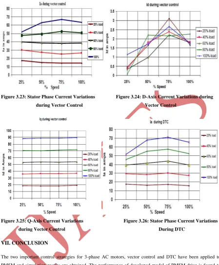
The variation in the current magnitude verses load is observed to be almost uniform at higher speeds. Fig.6-7
shows that the magnitude of „Id‟ is almost constant at base speed and that of „Iq‟ varies only with the load and its
variation with speed is almost negligible. Anon, the variation of „Iq‟ with load is almost uniform showing that
during vector control, the torque and speed are completely decoupled. Fig.8 shows the stator phase current
variations during DTC for different load and speed variations. The steady state magnitudes of the stator currents
are almost same as those in case of vector controlled PMSM drive as shown in Figure 3.24. From Figure 3.28 it
Figure 3.23: Stator Phase Current Variations Figure 3.24: D-Axis Current Variations during
during Vector Control Vector Control
Figure 3.25: Q-Axis Current Variations Figure 3.26: Stator Phase Current Variations
during Vector Control During DTC
VII. CONCLUSION
The two important control strategies for 3-phase AC motors, vector control and DTC have been applied to
PMSM and simulation results are obtained. The performance of developed model of PMSM drive is found to
work satisfactorily with the developed controllers in transient as well as steady state. The result shows that the
wide range of speed can be can be covered in vector control. The response of vector control for PMSM drive is
observed to be good load perturbation and transient condition, whereas DTC is better in terms of power
converter utilization at higher speeds and rated loads.
REFERENCES
[1] Gilbert C. D. Sousa, Bimal K. Bose and John G. Cleland; “Fuzzy Logic Based On-Line Efficiency
Optimization Control of an Indirect Vector-Controlled Induction Motor Drive”, IEEE Transactions On
[2] Isao Takahashi and Toshihiko Noguchi; “A New Quick-Response and High-Efficiency Control Strategy of
an Induction Motor”, IEEE Transactions On Industry Applications, Vol. Ia-22, No. 5. September/October
1986.
[3] Kuan-Teck Chang, Teck-Seng Low and Tong-Heng Lee; “An Optimal Speed Controller for
Permanent-Magnet Synchronous Motor Drives”, IEEE Transactions On Industrial Electronics, Vol. 41, No. 5,
October 1994.
[4] Bhim Singh, C.L.Putta Swamy, B.P. Singh, A. Chandra and K. Al-Haddad; “Performance Analysis of
Fuzzy Logic Controlled Permanent Magnet Synchronous Motor Drive”, Industrial Electronics, Control,
and Instrumentation, 1995., Proceedings of the 1995 IEEE IECON 21st International Conference
on (Volume:1 ).
[5] Alexander Verl and Marc Bodson; “Torque Maximization for Permanent Magnet Synchronous Motors”,
IEEE Transactions On Control Systems Technology, Vol. 6, No. 6, November 1998.
[6] M.F. Rahman, M.E. Haque, L. Zhong and M. Nagrial; “A Sensorless Speed Estimator for the Direct
Torque Control of an Interior Permanent Magnet Synchronous Drive”, Proceedings of International
Conference on Power Electronics Machines and Drives, 2002 p. 504 – 509.
[7] Hyun Lee and Jangmyung Lee; “Design of Iterative Sliding Mode Observer for Sensorless PMSM
Control”, IEEE Transactions On Control Systems Technology, Vol. 21, No. 4, July 2013.
[8] Jiangang Hu, Jingbo Liu, and Longya Xu; “Eddy Current Effects on Rotor Position Estimation and
Magnetic Pole Identification o PMSM at Zero and Low Speeds”, IEEE Transactions On Power
Electronics, Vol. 23, No. 5, September 2008.
[9] Todd D. Batzel and Kwang Y. Lee; “Electric Propulsion With Sensorless Permanen Magnet Synchronous
Motor: Implementation and Performance”, IEEE Transactions On Energy Conversion, Vol. 20, No. 3,
September 2005.
[10] Silverio Bolognani, Luca Tubiana and Mauro Zigliotto; “Extended Kalman Filter Tuning in Sensorless
PMSM Drives”, IEEE Transactions On Industry Applications, Vol. 39, No. 6, November/December 2003.
[11] Peter Sergeant, Frederik De Belie, Luc Dupré and Jan Melkebeek; “Losses in Sensorless Controlled
Permanent-Magnet Synchronous Machines”, IEEE Transactions On Magnetics, Vol. 46, No. 2, February
2010.
[12] Hongryel Kim, Jubum Son and Jangmyung Lee; “A High-Speed Sliding-Mode Observer for the
Sensorless Speed Control of a PMSM”, IEEE Transactions On Industrial Electronics, Vol. 58, No. 9,
September 2011.
[13] Zihui Wang, Kaiyuan Lu and Frede Blaabjerg; “A Simple Startup Strategy Based on Current Regulation
for Back-EMF-Based Sensorless Control of PMSM”, IEEE Transactions On Power Electronics, Vol. 27,
No. 8, August 2012.
[14] Antti Piippo, Marko Hinkkanen and Jorma Luomi; “Adaptation of Motor Parameters in Sensorless PMSM
Drives”, IEEE Transactions On Industry Applications, Vol. 45, No. 1, January/February 2009.
[15] Václav Šmídl and Zdenek Peroutka; “Advantages of Square-Root Extended Kalman Filter for Sensorless
Control of AC Drives”, IEEE Transactions On Industrial Electronics, Vol. 59, No. 11, November 2012.
[16] Naornitsu Urasaki, Tomonobu Senjyu and Katsurmi Uezato; “An Accurate Modeling for Permanent
[17] Todd D. Batzel and Kwang Y. Lee; “An Approach to Sensorless Operation of the Permanent-Magnet
Synchronous Motor Using Diagonally Recurrent Neural Networks”, IEEE Transactions On Energy
Conversion, Vol. 18, No. 1, March 2003.
[18] Reiko Raute, Cedric Caruana, Cyril Spiteri Staines, Joseph Cilia, Mark Sumner and Greg M. Asher;
“Analysis and Compensation of Inverter Nonlinearity Effect on a Sensorless PMSM Drive at Very Low and Zero Speed Operation”, IEEE Transactions On Industrial Electronics, Vol. 57, No. 12, December 2010.
[19] Sanjay Gairola and Ashish D. Thombre; “Modelling Of A Permanent Magnet Synchronous Motor Drive”,
Published in proceedings to National Conference in Recent drifts & Breaks in Applied Sciences &
Innovation Management, Krishna Institute of Engineering & Technology, Ghaziabad, August 7-9.
[20] Fabio Genduso, Rosario Miceli, Cosimo Rando and Giuseppe Ricco Galluzzo; “Back EMF
Sensorless-Control Algorithm for High-Dynamic Performance PMSM”, IEEE Transactions On Industrial Electronics,
Vol. 57, No. 6, June 2010.
[21] Oskar Wallmark, Lennart Harnefors and Ola Carlson; “Control Algorithms for a Fault-Tolerant PMSM