IJSRSET1738231 | Received : 11 Dec 2017 | Accepted : 31 Dec 2017 | November-December-2017 [(3) 8 : 991-998]
© 2017 IJSRSET | Volume 3 | Issue 8 | Print ISSN: 2395-1990 | Online ISSN : 2394-4099 Themed Section : Engineering and Technology
991
Electronic Toll Collection System Using Barcode Reader
B. Hasini
1, J. Maheswar Reddy
2PG Scholar, Department of ECE, Sir Vishveshwaraiah Institute of Science & Technology,Madanapalle, Chittoor, Andhra Pradesh, India1
Associate Professor, Department of ECE, Sir Vishveshwaraiah Institute of Science & Technology, Madanapalle, Chittoor, Andhra Pradesh, India2
ABSTRACT
This is a system to automate paying toll tax when a vehicle passes through tollbooth. Millions of vehicles pass through tollbooth paying toll tax. Currently available toll payment system uses manual methods. In this each vehicle has to stop at the tollbooth for payment. It causes traffic congestion and time consumption. Electronic toll collection is rapidly growing and becoming universally accepted technology. So, we focuses on an electronic toll collection (ETC) system using barcode reader technology. The system uses tags (barcode) that are mounted on the number plate of vehicles, or on the front side of vehicles through which information embedded on the barcode are read by barcode reader.
Keywords: Tollbooth, Vehicles, Traffic, Electronic Toll Collection and Barcodes.
I.
INTRODUCTION
The main idea behind implementing automated toll collection system is to automate the toll collection process and thus eliminating the long queues at tollbooths. The conventional system involves the process of stopping at the tollgate, giving toll to the tollgate staff, and take the ticket and return change(if any) only then the staff will raise the gate for the vehicle to pass through it. The entire system is very time consuming and make take a vehicle anywhere between 15mins-30mins depending upon the traffic conditions. ETC technology is very universally and rapidly accepted method. We can collect the toll electronically by using various methods like ETC using Laser technology, RFID, Barcode technology etc. The Barcode technology is very efficient than laser and RFID so we will discuss the barcode technology in detail. A barcode is a series of parallel black bars and white spaces, both of varying widths. Bars and spaces together are called elements. Different combinations of the bars and spaces represent different characters, such as numbers or letters. Each combination or sequence of bars and spaces is a code that can be translated into information such as price, product type, and place of manufacture. The barcode itself does not actually contain detailed information. The barcode simply
provides a reference number that tells a computer to access information. A barcode reader is required to read a barcode. Barcode readers may be fixed, portable batch, or portable RF. Fixed readers are attached to a host computer and terminal, and transmit one item at a time as the data is scanned. Barcodes are simple to use, accurate, and quick. Almost everyone is familiar with their use in retail establishments. They are also often used in ware-houses and manufacturing for selecting items from storage, receiving goods, and shipping. There are different types of barcodes. Some bar-codes are entirely numeric, whereas others have numeric and alphabetic characters. The type used is dependent upon the implementation, the data that needs to be encoded, and how the barcode is to be printed. There are several barcode standards, called symbolize, each serving a different purpose. Each standard defines the printed symbol and how the scanner reads and decodes the printed symbol.
II.
Existing System
Laser scanner as vehicles passed the toll booths. However the scanner had poor reading reliability and it was sensitive to weather and dirt and has to be located as close as possible to toll booth. To overcome these disadvantages, ETC using RFID technology was introduced. It has high accuracy and could be read even in highway speed. The RFID Technology is much better than the LASER Technology because it has a high accuracy than the Laser scanner. But the RFID Technology also had disadvantage that it is work on the radio frequency, so the device or scanner require to capture that radio frequency is mounted on the upper side or somewhere in tollbooth. If he/she doesn’t maintain the speed the vehicle will break the barrier. This is the disadvantage of the RFID Technology. Work towards turning out the above mentioned disadvantages to the advantages and make a proposal for its optimization.
III. Proposed System
The proposed system eliminates toll authorities to manually perform ticket payments and collection of cash. It is more efficient method because it reduces the traffic and possible human errors by exchanging the data information between the motorists and toll authorities. Barcodes are much smaller and lighter and therefore easier to use. Barcodes are less expensive than RFID tags because barcodes are directly printed onto material such as plastic or paper materials and therefore the only cost involved is the ink. This technology has many advantages such as automatic and accurate toll collection, improvement in highway efficiency and low fuel consumption.
Block Diagram:
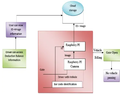
Figure 1: Block Diagram Of Etc Using Barcode Reader
This project is mainly developed for Electronic Toll Collection by Using Barcode Scanner. This project
mainly consists of a raspberry pi microcontroller, Pi camera, barcode scanner, motor driver and a gear motor. Initially we will connect a Pi camera to the raspberry pi microcontroller which will be able to capture the image in front of that. We are connecting the barcode scanner to the raspberry pi which will be able to read the barcode present on the vehicle that is nothing but a number plate of a car. After detecting the number plate it sends the information to the server where it can able to opens the owner information and collects the money from his/her account then automatically toll gate will open. If he/she fails to transfer the amount from the account then the toll gate will not open the gate.
Architecture:
Figure 2 : Etc Architecture
Fig 2 gives the complete architecture of electronic toll collection to the vehicle allowed to pass through the toll. As the vehicle approaches towards the toll, barcode scanner scans the barcode on the vehicle and identifies the owner details to check if an existing user with active credentials to make online transaction. In parallel to that the raspberry pi camera captures the vehicle image which categorizes to which tariff payment to be made by the owner. Once the online payment is done the raspberry pi triggers the motor to open the gate through which the vehicle is allowed to pass through the toll to avoid any hassles of traffic congestion, money exchange from user to toll keeper.
Overview of Raspberry pi: Raspberry pi
Pi was introduced as an instructive contraption which will be utilized for prototyping by specialists and for the individuals who ever takes it more about the programming. It definitely cannot be a substitute for our day today Windows PC, Linux or Mac.
Pi mainly depends on a Broadcom SoC (System of Chip) including an ARM processor [which is of ~700 MHz], a GPU and the RAM ranging from 256 upto 512 MB. For any continuous data exchange, it uses a SD card which is of more like a boot media. Since you are aware of it that the RAM and the processing power are not nearby to the power house machines that are available at home, these Pi's can be utilized as a basic computers for some simple functions. Actually the Pi comes in three configurations and the details of the same will be discussed in the upcoming sections. For a B model Pi it is costing around $35 and is numerously available through the web or physical stores.
Raspberry pi system specifications:
As examined before the Pi comes in three designs. The following is a table that gives the insights about each of the three models in particular A, B and B+.
Chip: All the model A, B and B+ uses Broadcom BCM2835 (CPU, GPU, DSP, SD RAM and single USB port.
Processor: For all the three models it uses700MHz ARM1176JZF-S core (ARM11 family, ARMv6 instruction set.
RAM: Model A has got the storage of 256 MB whereas Model B, B+ is provided with 512MB.
USB: Model A is facilitated with 1 USB port which is direct from BCM2835 chip itself; Model B is provided with 2 on board ports and Model B+ is provided with 4 on board ports.
Storage: Model A and B uses SD Card where Model B+ uses Micro SD Card.
Voltage: Model A is provided with 600mA up to 1.2Aat 5 Volts; Model B is provided with 750mA up to 1.2A at 5 Volts; Model B+ is provided with 600mA up to 1.8A at 5 Volts.
GPO: Model A and B is provided with 26 pins and Model B + is provided with 40 pins
We will be picking Model B and shall be detailing more about this model in the upcoming sections. On the off chance that in the event that you are asking why B and not B+, this is on the grounds that I just possess a B and not a B+.
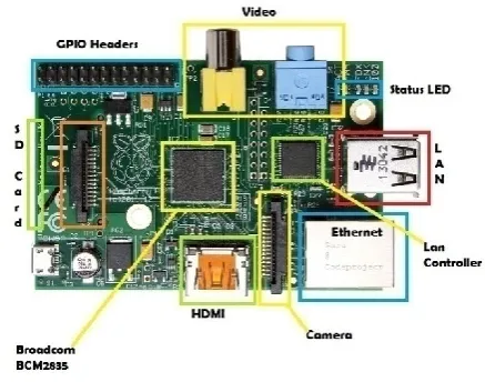
Figure 3 : Raspberry Pi Model
Ports, pins and its uses:
Details of the ports that are available on the Raspberry Pi board and some of its uses are discussed below. These ports can also be utilized for any other purposes also apart from the listings below.
USB
USB ports are actually operated for peripherals like keyboard, mouse and a Wi-Fi Adapter. A controlled USB center point can be associated and it can also be extended
HDMI
It is the High Definition Multimedia Interface [HDMI] and is used to fix to a Display unit like TV or Monitor or even sometimes to connect to a projector
Stereo
Audio Audio associations utilizing a 3.5 mm jack
SD Card
SD card is utilized as a boot gadget and furthermore relentless capacity. More storing can be connected to the USB
Micro USB
The miniaturized scale USB port is utilized for providing power supply to the unit
CSI Connector
Ethernet Used for interfacing with a system with the help of a network cable
DSI Connector
DSI [ Digital serial Interface] is utilized for associating a LCD
Table 1: Ports, Pins And Its Uses
All together there are 26 Pins on a Model B where the details of it described below.
3 power supply pins [3.3v, 5.0v and 0v].
6 Do Not Connect (DNC) pins
17 GPIO pins(GPIO-General Purpose Input and
Output)
Towards the end of this section, more to get an understanding about how these GPIOs are used we shall be discussing about some simple circuits. Even before that we will be detailing about the Pi setup with an Operating system.
Raspberry Pi with Raspbian OS:
Will discuss about some of the Operating systems where a Pi can operate but here we will be detailing more about Raspbian.
Linux
3 official Linux flavors are available for download namely
1. Debian [Raspbian] – which is
recommended
2. ArchLinux
3. Pidora [Based on Fedora]
RISC OS
A retro looking 1080p GUI designed by the ARM designers. RISC was more predominantly used during the 90's
Firefox OS
This is a new OS from the Firefox team. It is more of a combination of Firefox and PTX dist-built Linux
Plan 9 Unix like OS by the Bell Labs,
generated by the UNIX creators
Android No other explanation necessary, it was
certain that it haven’t gone beyond a 2.3
build and is of bit slow too.
Table 2: Operating systems
Pi with Operating System:
One of the authorized Operating Systems that are freely available to download or to use is Raspbian OS. The framework of it mainly depends on Debian Linux and is restructured to work effectively with the Raspberry Pi PC. For this circumstance of the Pi, we definitely know that OS is an arrangement of essential projects and utilities that keeps running on a predefined environment. Debian is extremely lightweight and settles on an incredible decision for the Pi. The Raspbian incorporates devices for perusing, python programming and a GUI desktop.
The Raspbian desktop circumstance is called as the "Lightweight X11 Desktop Environment" or in a simple word LXDE. This has a genuinely appealing UI that is constructed utilizing the X Window System programming and is a natural point and snap interface. In the following sections we might look more into how to introduce and utilize this OS in different applications as intended.
Description of Hardware components: Barcode Scanner:
A standardized identification per user or scanner is an electronic gadget for perusing printed scanner tags. Like a flatbed scanner, it comprises of a light source, a focal point and a light sensor making an interpretation of optical driving forces into electrical ones. Also, almost all standardized tag reader contain decoder hardware dissecting the standardized identifications picture information gave by the sensor and sending the scanner tags substance to the scanner's yield port.
Camera Hardware:
This section attempts to provide an overview of the operation of the camera under various conditions, as well as to provide an introduction to the low level software interface that pi-camera utilizes.
Camera Modes:
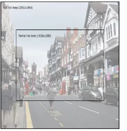
Note: This table is accurate as of firmware revision #656. Firmware’s prior to this had a more restricted set of modes, and all video modes had partial FoV. Please use sudo apt-get dist-upgrade to upgrade to the latest firmware.
Modes with full field of view (FoV) capture from the whole area of the camera’s sensor (2592x1944 pixels), using the specified amount of binning to achieve the requested resolution. Modes with partial FoV only capture from the center 1920x1080 pixels. The difference between these areas is shown in the illustration below:
PI CAMERA INPUT MODES
Figure 4 : PI camera input mode
Camera modes of operation and view:
The input mode can be manually specified with the sensor mode parameter in the PiCamera constructor (using one of the values from the # column in the table above).
Under the Hood:
This section attempts to provide detail of what picamera is doing “under the hood” in response to various method calls.
The Pi’s camera has three ports, the still port, the video port, and the preview port.
Encoders:
The camera provides various encoders which can be attached to the still and video ports for the purpose of producing output (e.g. JPEG images or H.264 encoded video). A port can have a single encoder attached to it at any given time (or nothing if the port is not in use).
Dc motor/Motor driver:
In some of the electronics projects you may want to control a DC Motor with microcontrollers. The maximum current that can be sourced or sunk from a microcontroller is 15mA at 5v. But a DC Motor need currents very much more than that and it need voltages 6v, 12v, 24v etc, depending upon the type of motor used. Another problem is that the back emf produced by the motor may affect the proper functioning of the microcontroller. Due to these reasons we can’t connect a DC Motor directly to a microcontroller.
Figure 5: DC Motor
To overcome these problems you may use a H-Bridge using transistors. Freewheeling diodes or Clamp diodes should be used to avoid problems due to back emf. Thus it requires transistors, diodes and resistors, which may make our circuit bulky and difficult to assembly.
To overcome this problem the L293D driver IC is used. It is a Quadruple Half H-Bridge driver and it solves the problem completely. You needn’t connect any transistors, resistors or diodes. We can easily control the switching of L293D using a microcontroller. There are two IC’s in this category L293D and
L293
. L239D can provide a maximum current of 600mA from 4.5V to 36V while L293 can provide up to 1A under the same input conditions. All inputs of these ICs are TTL compatible and clamp diodes is provided with all outputs. They are used with inductive loads such as relays solenoids, motors etc.(IN3-OUT3, IN4-OUT4). We can drive two DC Motors using one L293D, but here we are using only one. You can connect second DC Motor to driver pair 2 according to your needs.
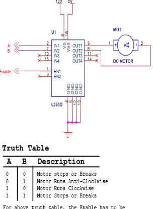
L293d Dual H-Bridge Motor Driver:
L293D is a dual H-Bridge motor driver, So with one IC we can interface two DC motors which can be controlled in both clockwise and counter clockwise direction and if you have motor with fix direction of motion the you can make use of all the four I/Os to connect up to four DC motors. L293D has output current of 600mA and peak output current of 1.2A per channel. Moreover for protection of circuit from back EMF ouput diodes are included within the IC. The output supply (VCC2) has a wide range from 4.5V to 36V, which has made L293D a best choice for DC motor driver.
Figure 6: A simple schematic for interfacing a DC motor using L293D
As you can see in the circuit, three pins are needed for interfacing a DC motor (A, B, Enable). If you want the o/p to be enabled completely then you can connect Enable to VCC and only 2 pins needed from controller to make the motor work.
As per the truth mentioned in the image above its fairly simple to program the microcontroller. It’s also clear from the truth table of BJT circuit and L293D the
programming will be same for both of them, just keeping in mind the allowed combinations of A and B.
IV. RESULTS AND DISCUSSIONS
In this project the entire output is based on the Raspberry Pi Controller, which controls the motor output to close or open which gate to allow the vehicle to pass through the toll gate.
Figure 7: Proposed system model
Experimental setup for the proposed system:
Above figure shows the entire setup of a proposed system which comprises of Raspberry Pi Module, Barcode Reader Module, Cloud Server Module, Recharge and Deduction Module, Gate Operation Module using a DC motor.
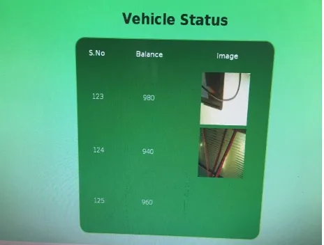
Figure 8: Vehicle status
Online web update:
the respective accounts the toll amount will get deducted at each of the toll gates when it is required to pass through. If the amount is available in the user account, with the user credentials submitted it will trigger the response as a success inturn opens the toll gate to pass through. Otherwise if the amount is not available in the user account it will trigger with a response of failure which requires to make a recharge and do the online transaction only then the toll gate is open.
Figure 9: Barcode scanning status-success
Figure 10: online web page after detection
Above figure gives the response of success/failure status when the barcode reader scans the barcode. Once the status is success means that the online account also gets updated with the deducted amount and reflects as shown in the figure.
Figure 11: Barcode scanning status-failure
The approach for this implementation is, there should be created a database for the vehicle information where this data is more centralized to access anywhere in India. That is how this project works on. There is a possibility that if any vehicle is not registered and the vehicle details are not available in the database it will show an error/failure status as shown in figure where it will not allow the user to pass though that toll gate.
V.
CONCLUSION
Applications:
Used in the healthcare and hospital settings
Used in grocery stores
Used to keep track of objects and people
Barcodes are widely used in shop floor control applications software where employees can scan work orders and track the time spent on a job.
Vehicle theft control.Advantages:
Eliminates the human interaction in
User friendly
Reduces the cash handling.VI. REFERENCES
[1]. RFID based toll collection system, 2011 IEEE third international Conference.
[2]. V. Chawla and D. S. Ha, "An overview of passive RFID," Communications Magazine, IEEE, vol. 45, pp. 11-17, 2007.
[3]. P. Blythe, "RFID for road tolling, road-use pricing and vehicle access control," in RFID Technology (Ref. No. 1999/123), IEE Colloquium on, 1999, pp. 8/1-816. [4]. N. Gabriel, I. Mitraszewska, K. Tomasz, “The Polish
Pilot Project of Automatic Toll Collection System”, Proceedings of the 6th International Scientific Conference TRANSBALTICA, 2009.
[5]. Y. Cheng, and M. Wang, "An RFID electronic tag based automatic vehicle identification system for traffic iota applications," in Control and Decision Conference (CCDC), 2011 Chinese, 2011, pp. 4192-4197.
[6]. SachinBhosale,DnyaneshwarNathaWavhal.
“Automated Toll Plaza System using RFID” IJSETR, Vol 2, Issue 1, Jan 2013.
[7]. Asif Ali Laghari, M. SullemanMemon and Agha SherazPathan, “RFID Based Toll Deduction System,”I.J. Information Technology and Computer Science, 2012, 4, 40-46
[8]. Abhishek Sharma, Arpit Yadav, Anurag PArmar, AUTOMATIC TOLL SYSTEM, 2014 IJIRT | Volume 1 Issue 6.