Particle Swarm Optimization Based Fuzzy-Neural Like
PID Controller for TCP/AQM Router
Mohammed Z. Al-Faiz, Shahad A. Sadeq
Computer Engineering Department, College of Engineering, Nahrain University, Baghdad, Iraq Email: [email protected], [email protected]
Received September 19, 2011; revised October 24, 2011; accepted November 2,2011
ABSTRACT
In this paper a PID Fuzzy-Neural controller (FNC) is designed as an Active Queue Management (AQM) in internet routers to improve the performance of Fuzzy Proportional Integral (FPI) controller for congestion avoidance in com-puter networks. A combination of fuzzy logic and neural network can generate a fuzzy neural controller which in asso-ciation with a neural network emulator can improve the output response of the controlled system. This combination uses the neural network training ability to adjust the membership functions of a PID like fuzzy neural controller. The goal of the controller is to force the controlled system to follow a reference model with required transient specifications of minimum overshoot, minimum rise time and minimum steady state error. The fuzzy membership functions were tuned using the propagated error between the plant outputs and the desired ones. To propagate the error from the plant outputs to the controller, a neural network is used as a channel to the error. This neural network uses the back propagation algo-rithm as a learning technique. Firstly the parameters of PID of Fuzzy-Neural controller are selected by trial and error method, but to get the best controller parameters the Particle Swarm Optimization (PSO) is used as an optimization method for tuning the PID parameters. From the obtained results, it is noted that the PID Fuzzy-Neural controller pro-vides good tracking performance under different circumstances for congestion avoidance in computer networks.
Keywords: Neural Networks; Fuzzy Logic; PID Controller; AQM; PSO; Computer Network
1. Introduction
The term “congestion control” is used to describe the efforts made by network nodes to prevent or respond to overload conditions. Congestion in a computer network is a state in which performance degrades due to the satu- ration of network resources such as communication links, processor cycles, and memory buffers. Network conges- tion has been well recognized as a resource-sharing problem. When too many packets are difficult to be de- scribed as a mathematical model, and the controller can be designed to apply heuristic rules contending for the same link, the queue overflows and packets have to be dropped.
When such drops become common events, the net-work is said to be congested. Most netnet-works provide a congestion-control mechanism to deal with just such a situation [1]. The Internet Engineering Task Force (IETF) has proposed the deployment of active queue manage-ment (AQM) mechanisms [2]at gateways to improve the performance of TCP congestion control. AQM has been a very active research area in the Internet community. Random early detection (RED) [3]is an extensively stu-died AQM algorithm that can detect congestion. It con-trols congestion by randomly dropping packets with
certain probability that is a function of the average queue size (qavg). In recent years, the more needs for the
con-gestion controllers having enough ability which is more logically predictable and reliable are occurred. For this reason, the traditional control algorithms which have been used only for mechanical or electrical systems are adopted to the area of congested network and their per-formances which are known as relatively good. Conse-quently, the more controllers which have various fea-tured types have been adopted to the network congestion control area using control theories. On the issue of ap-plying control theories to the network, especially AQM Router, a proportional (P) controller and a proportional- plus-integral (PI) controller for AQM [4]were designed based on the classical control theory and the dynamic model of the TCP congestion control [5] and its liearized model [6]. And also, [7] proposed an adaptive fuzzy AQM for congestion avoidance in TCP/AQM networks. More recently [8] developed a new AQM algorithm based on neural networks. The proposed controller is simple and can be easily implemented in high-speed routers.
Here, a Fuzzy-Neural like PID controller based PSO is designed as an AQM for internet router.
Developments in intelligent control had been made in the past years through the development of fuzzy logic control (FLC) and Neural Networks (NN) [10].
The main advantage of the Fuzzy Logic Controller (FLC) is that it can be applied to plants that are that re-flect the experience of human experts. PID FLCs have been successfully applied to a variety of practical prob-lems. In spite of its practical success, there is no standard procedure for tuning PID FLCs [11].
Artificial Neural Network (ANN) is a combination of processing elements that perform certain tasks through learning weights.
Neural Networks provide a different approach to problem solving from linguistic or algorithmic systems such as FLC.
By combining both algorithms of NNs and FLCs to-gether a robust controller may be achieved, which can give precise actions and learn to enhance its performance. A FLC can represent human reasoning while NN can simulate human learning [12].
The organization of the paper is as follows: Section 2 describes the linearized AQM model. Section 3 describes the Fuzzy Neural Network (FNN) design.
The simulation results are given in Section 4 to verify the proposed controller using MATLAB package. Finally, a conclusion is given in section 5.
2. TCP/AQM System Model
AQM has been extensively analyzed using control-theo- retical methods. Control-theoretical approaches lead to stable, effective, and robust congestion control operation. In [5], the non-linear dynamic model for multiple TCP flows control has been developed based on fluid-flow theory to model the interactions of a set of TCP flows and AQM routers in computer networks which consist of a system of nonlinear differential equations. For the con-trol theoretical analysis, it was approximated as a lin-earized constant model by small signal linearization about an operating point (W0, q0, p0), see [6] for
lineari-zation details, which leads to the following :
2
0 22p t R
0
0
2
2
R C N
W t W t
R C N
(1)
0 0
1
t q t R R
W t
N q t W
(2) where δW(t) ≈ W − W0, δq(t) ≈ q − q0, δp(t) ≈ p − p0,
denotes the time-derivative of W(t), q t
de-notes the time derivativeof q(t), and
W: Expected TCP window size (packets);
q: Expected queue length (packets);
R0: Round-trip time (seconds);
C: Link capacity (packets/second);
N: Load factor (number of TCP sessions);
p: Probability of packet mark/drop;
t: Time.
The expected queue length q and the expected TCP window size W are positive value and bounded quantities. And also, the probability of packet (mark/drop) p takes value only in [0,1].
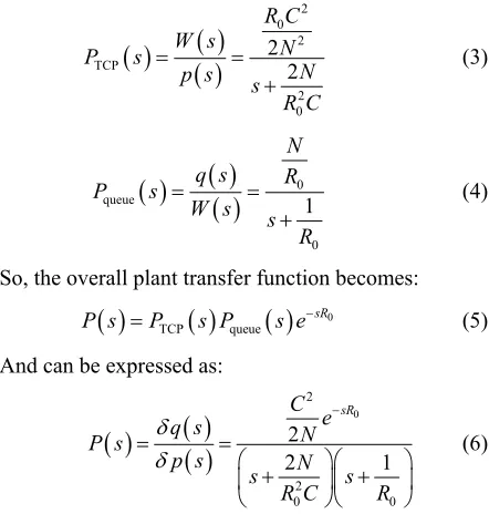
Taking the Laplace transform of Equation (1) and re-arranging the following transfer functions are obtained:
2 0 2 TCP 2 0 2 2 R C W s N P s
N p s s
R C
(3) 0 queue 0 1 N q s R P sW s s R
(4)
So, the overall plant transfer function becomes:
0TCP queue
sR
P s P s P s e
(5) And can be expressed as:
0 2 2 0 0 2 2 1 sR C e
q s N
P s
p s N
s s R R C
(6)Thus, the block diagram of linearized AQM control system is shown in Figure 1. In this diagram PTCP (s)
denotes the transfer function from loss probability δp(t) to window size δW(t), Pqueue(s) denotes the transfer
func-tion from δW(t) to queue length δq(t), and C(s) denotes the transfer function of controller. Taking the Z-trans- form to Equation (6), the designed plant transfer function is obtained after considering the sampling time half of R0.
Precisely and for consider the case study with N = 60, C
= 3750 packets/sec and R0 = 0.253 sec the following
dis-crete transfer function are obtained.
3
1 2
11252.46 1 1.545 0.569
q z z
P z
p z z z
+ Controller (7) ) (s
C esR0 Ptcp(s) Pqueue(s)
) (s P -Plant ref
q Saturation p W q
[image:2.595.318.539.210.442.2]3. Fuzzy Neural Network Design
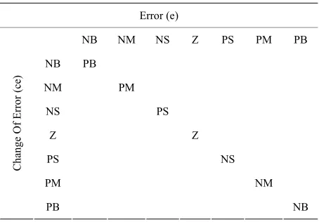
In order to design a FNC a Neural Network (NN) should be designed first. This NN represents the structure of FLC. It’s called Fuzzy Neural Network (FNN) Structure. In this work, it assumed that a Mamdani type FLC with two inputs of error and rate of error and one output is used. The memberships used for the inputs and output are bill shaped type with 7 memberships for each. These rules are reduced from 7 × 7 to 7 only since any input has some contribution in all of the fuzzy sets and will circle around the main diagonal of the fuzzy rule table and set-tle in the center of this table. Hence, fuzzy rule table will be as shown in Table 1.
where the abbreviations of the table represent: PB as Positive Big, PM as a Positive Medium, PS as Positive Small, Z as Zero, NS as Negative Small, NM as Negative Medium and NB as Negative Big. Moreover, the rules are implied using product for AND operation. Further-more, the defuzzification used in this controller is a cen-ter of gravity type.
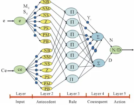
3.1. FNN Structure
The structure of FNN is shown in Figure 2. This
struc-ture consists of five layers which are:
1) Input layer: in the input layer, each node transmits the corresponding input to the antecedent layer, thus:
1
i i
X I
1 1
i i
O X
i
(8) and
(9) where
I is the ith network input,
1
i
X is the node input, and
i
I is the node output.
The subscript refers to the node number while the su-perscript refers to the layer number.
[image:3.595.59.286.580.738.2]2) Antecedent layer: this layer will transmits each
Table 1. Rules of fuzzy logic controller.
Error (e)
NB NM NS Z PS PM PB
NB PB
NM PM
NS PS
Z Z
PS NS
PM NM
Ch
an
ge
Of Er
ro
r
(ce)
PB NB
value of input to the corresponding linguistic set, hence:
2 1
2 1
2
j ij
i
ij
O m
X
s
22 Xi
i
O e
3 2 2
7
i i i
(10) and
(11) where i = 1,2 ··· 14, j = 1,2,, mij is the center of bill
shaped fuzzy membership function, sij is the standard
deviation, i refers to the antecedent node while j refers to the input node.
3) Rule layer: this layer performs the implication of AND operation. The rule is implied using product opera-tion. Since only 7 rules will contribute the rules which represent the diagonal of the fuzzy rule table mentioned in Table 1, then:
X O O
3 3
i i
O X
4 3
1 1
n i i i
(12) and
(13) where i = 1,2 ··· 7.
4) Consequent layer: only two nodes are available in this layer which performs the center of gravity defuzzifi-cation algorithm. The first node has a weighted input and the second is of the strength of unity, thus:
X O y
4 3
2 1
n i i
(14)
X O
(15) and4 4
i i
O X
y
(16) where i = 1,2. n is the number of rules i is the weight
between the rule and the consequent layers.
5) Action layer: the completion of center of gravity defuzzificztion algorithm is done in this layer, so the input and output of each node is given by:
4
5 1
4 2
O X
O
5 5
O X
(17) and
(18)
3.2. FNN Learning Algorithm
1) Consequent layer (layer four):
3
4 5
2k O k O
1 i d
i i
O O
y k y k (19)
where η is the learning rate, Od is the desired output.
2) Antecedent layer (layer two): In this layer, the learning equation of back propagation is:
3 5
j
O k O k
1 5
2 4 2 1
ij i d
j i i
ij
m k m k O O m y k O k
O s
(20)
and
5
2 1
3 2 4.
j ij
ij
5
1
ij ij d
i
s k s k
y k O k
O k O k
O m
O s
dI
K e t t
(21)
Equations (19), (20), and (21) will perform the back propagation procedure. Initializing the parameters in FNN is very important since it may reduce the learning time of the network, thus these parameters have been chosen at the same bases of choosing them in an ordinary fuzzy logic controller. That is mij will divide the universe
of discourse to 7 equal intervals, while sij will give the
bill shaped functions a reasonable width. Finally, yi is
scattered along the output universe of discourse in an equal intervals.
3.3. PID-Like Fuzzy Neural Controller (PID-FNC)
The equation of PID controller in time domain is:
P
D ( ) [image:4.595.59.282.546.725.2]u t K e t K e t (22) where KP, KI and KD are the proportional, integral and
Figure 2. Fuzzy neural network structure (FNN).
derivative gains of the PID respectively.
Thus, in the discrete case of a PID like fuzzy controller one has an additional process state variable, namely sum- of-error to dente the integral part. Unfortunately, if any input is described with (m) linguistic value, then since PID controller has three inputs and since any rule has three conditions, then there is a need of m × m × m = m3
rules. So, it is too much work to write m3 rules. The PID-
like fuzzy controller can be constructed as a parallel structure of a PD-like fuzzy controller and a PI-like fuzzy controller and the output can be approximated as [13]:
2 1
d
a b P D
P I
u t u u K e K e t
K e K e t
(23)However, the first part of Equation (23) represents PD controller. PD controller for any pair of the values of e and δe, calculates the control signal (ua).
1
a P D
u t K e t K e t (24) The fuzzy controller should do the same thing. For any pair of error (e) and change of error (δe), it should work out the control signal though rules. In fuzzy rules, the sampling time will be omitted since such a rule expresses a causal relationship between the process state and con-trol output variables, which holds for any sampling time. Moreover, the second part of Equation (23) represents PI controller, which can represent PI like fuzzy controller. The Fuzzy controller and the rules table have other inputs; error and sum of error. It means that, the rules them-selves should be reformulated. Since only the diagonal of the rule table will be used, it is found that the rules of PI-controller part are the same rules mentioned in Table 1. However, the equation of PI controller is:
2
db P I
u t K e t K
e t t (25) The proposed PID-FNC will consist of two FNNs. The first one is for PD like controller action mentioned in Equation (23), while the second FNN is for PI like con-troller action mentioned in Equation (25). The general block diagram of PID-FNC is shown in Figure 3. Theparameters of Kuaand Kubare the output scaling factors of
PD like and PI like fuzzy controllers respectively. It will be assumed in this work that there is no need to any rule definition, since the rule layer is fixed and take the opti-mal rules of the fuzzy logic controller. However, the general Block Diagram of the PID-FNC Controlled Sys-tem is shown in Figure 4. In this figure, Neural Network
Figure 3. General block diagram of PID-FNC.
Figure 4. General block diagram of PID-FNC controlled system.
error between the plant output and the reference model output to generate both error, sum of error and change of error internally. Then after generating the controller ac-tion, it updates its weights using FNCe; which is the error between the reference model output and the plant output propagated through NNE.
4. Simulation
In this section the proposed controller is evaluated using MATLAB.
Figure 5 shows the network topology used for this set
of simulation in which the shared bottleneck link be-tween router R1 and router R2 has a capacity of 15 Mbps
with propagation delay of 20 ms and N = 60 and the packet size is set to be 500 bytes and the reference input (queue size) which has rectangular form changes every 50 seconds as shown in Equation (26).
200 400 200 300
qref
; 200 150
; 150 100
; 100 50
; 50 0
t t t
t
(26) The maximum queue length in the AQM router Router 1 is 800 packets. The AQM mechanism is configured at Router1, and drop Tail is used at other gateways
[image:5.595.61.285.82.311.2]First the simulation is done for the system without controller as shown Figure 6.
Figure 6 shows that the system without controller is
unable to track the queue length around the queue length to the desired level, where the system goes into a sus- tained oscillation with high congestion exceeding the
S1 D1
D60 S2
S60 15 Mbps 15 Mbps
Router 2 Router 1
D2 15 Mbps
Bottleneck Link
15 Mbps 15 Mbps
15 Mbps 15 Mbps
Round Trip Time (R0=0.253 sec)
Figure 5. Network topology case study.
Figure 6. System response without controller.
maximum buffer size. In [9] a classical control (PI-con- troller) is applied in order to eliminate this sustained os-cillation and get better tracking performance, also FPI controller is designed to speed up the system response, and FPI based genetic is designed to get the best pa-rameters of FPI controller and to enhance the system response.
In this paper we used the PSO as a suitable optimiza-tion method for tuning FPI Parameters, the PSO parame-ter was: population size 80, the inertia weight factor w is 0.9, acceleration constant c1 = 1.2 and c2 = 0.12 and the
fitness function is the integral time absolute error
0
ITAE
T T qref q3
1 10
The FPI parameters obtained in PSO are (Kp =
3
1 10
,
Ki = , Ku = 5 10 3).
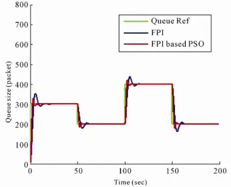
It is found that that the FPI baesd PSO is better than FPI and could speed up the system response with less computation time than FPI based G.A as shown in Fig-ure 7.
Although the FPI based PS0 shows good performance the system response has overshoot and to overcome this drawback, first we design a Fuzzy-Neural like PI (FNPI) controller to can compare it with FPI and show how can the addition of NN can improve the system response.
[image:5.595.118.226.566.621.2]only of Figure 3.
The FNPI controller parameters are selected first by trial and error method as follows (Kp2 = 200, Ki =
7761200, Ku = ) and then by using PSO method
to find the best parameters of FNPI, we get (Kp2= 300, Ki
= 8861200, Kub = ). As shown in Figures 8 and 9.
3
3 10
3
2 10
5
1 10 2 103
From Figure 9 it was found the FNPI based on PSO is
better than FPI based PSO by decreasing the overshoot of the system response.
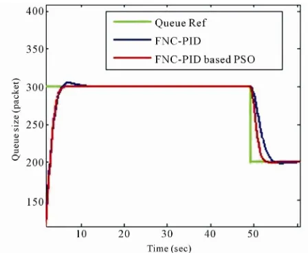
Finally we design a Fuzzy Neural Controller like PID (FNC-PID) and show how it can improve the system response more than the FNPI.
The FNC-PID parameters are selected first by trial and error method as follows (Kp1= 1, Kd = 50.1261, Kua =
, Kp2= 80.2745, Ki = 50.2638, Kub = ).
[image:6.595.59.284.303.486.2]and then by using PSO method to find the best parame-
[image:6.595.311.536.306.483.2]Figure 7. System response with FPI and FPI based PSO controller.
Figure 8. System response with FNPI, FNPI based PSO controller.
ters of FNC-PID, we get (Kp1= 100.1616, Kd = 20.1261,
Kua = 1 10 5, Kp2= 140.5, Ki= 30.2638, Kub= 2 10 3)
as shown in Figures 10 and 11.
Figure 11 shows that FNC-PID based PSO is best than
FNPI based PSO controller by making the response of the system more faster with zero overshoot.
The overall simulation results are shown in Table 2.
5. Conclusions
From the design and the simulation results, it can be con-cluded that:
1) The designed FPI based PSO is better than FPI which can improve the system response by decreasing it’s overshoot and make it more faster by decreasing it’s settling time which proves the efficiency of PSO as a suitable optimization method.
2) By using the PSO to optimally select the best pa
[image:6.595.310.536.525.707.2]Figure 9. System response with FPI based PSO, FNPI based PSO controller.
[image:6.595.60.284.525.709.2]Figure 11. System response with FNPI based PSO, FNC- PID based PSO controller.
Table 2. TCP/QAM system response performance of FPI, FNPI, and FNC-PID based PSO with error criteria 5%.
Settling Time
tp (sec)Peak Time
p% p
M t (sec)
Overshoot Rise Time
Mp%
(sec) Controller8 5
54 4
FPI
4 3
28 2.5
FPI-PSO
12 3.8
60 2.7
FNPI
13 7
5 5.7
FNPI-PSO
15 4.7
29 3.8
FNC-PID
7 -
- 6.5
FNC-PID-PSO
rameters of FNPI, the system response is improved by decreasing its overshoot as shown in Table 2 which also
proves the efficiency of PSO as a suitable optimization method.
3) The designed FNPI based PSO controller can de-crease the overshoot of system response comparing with FPI based PSO controller.
4) The designed FNC-PID based PSO is better than FNC-PID controller which can improve the system re-sponse by making its overshoot zero and faster by de-creasing its settling time which also proves the efficiency of the PSO as a suitable optimization method.
5) The designed FNC-PID based PSO controller can decrease the overshoot of system response of FNPI based PSO controller by making it zero and make the system response faster by decreasing its settling time.
6) The designed FNC-PID based PSO controller can
deal with congestion problem with a good tracking per-formance about the desired queue size with high link utilization and faster system response.
REFERENCES
[1] L. Peterson and B. Davie, “Computer Network a Systems Approach,” 3rd Edition, Morgan Kaufmann, Waltham, 2003.
[2] B. Braden, D. Clark and J. Crowcroft, “Recommenda-tions on Queue Management and Congestion Avoidance in the Internet,” Network Working Group, Internet Soci-ety, Reston, 1998.
[3] S. Floyd and V. Jacobson, “Random Early Detection Gateway for Congestion Avoidance,” IEEE Transactions on Networking, Vol. 1, No. 4, 1993, pp. 397-413. doi:10.1109/90.251892
[4] C. V. Hollot, V. Misra, D. Towsley and W. B. Gong, “On Designing Improved Controllers for AQM Routers Sup-porting TCP Flows,” Proceedings of IEEE INFOCOM, Anchorage, 24-26 April 2001, pp. 1726-1734.
[5] V. Misra, W.-B. Gong and D. Towsley, “Fluid-Based Analysis of a Network of AQM Routers Supporting TCP Flows with an Application to RED,” Proceedings of the Conference on Applications, Technologies, Architectures,
and Protocols for Computer Communication, Stockholm, 28 August-1 September 2000, pp. 151-160.
[6] C. V. Hollot, V. Misra, D. Towsley and W. B. Gong, “A Control Theoretic Analysis of RED,” Proceedings of IEEE
INFOCOM, Anchorage, 24-26 April 2001, pp. 1510-
1519.
[7] M. Jalili, F. Roudsari, A. Dehestani and H. Fesharaki “Adaptive Fuzzy Active Queue Management,” Proceed-ings of FORTE Workshops, Islamic Azad University, Te-hran, 2004, pp. 196-208.
[8] M. Y. Waskasi, M. J. Yazdanpanah and N. Yazdani, “A New Active Queue Management Algorithm Based on Neural Networks PI,” University of Tehran, Tehran, 2005. [9] M. Z. AL-Faiz and A. M. Mahmood, “Fuzzy Genetic
Controller for Congestion Avoidance in Computer Net-works,” Proceeding of Engineering Conference on Con-trol, Computer and Mechatronics, Baghdad, 30-31 Janu-ary 2011, pp. 206-212.
[10] B. Kosko, “Neural Networks and Fuzzy Systems,” Pren-tice Hall, Upper Saddle River, 1992.
[11] D. T. Pham, “Neural Networks for Identification, Predic-tion and Control,” Springer, Berlin, 1995.
doi:10.1007/978-1-4471-3244-8
[12] M. Brown, and C. Harris, “Neuro-Fuzzy Adaptive Mod-eling and Control,” Prentice-Hall Inc., Englewood Cliffs, 1994.