Abstract — This paper presents the design and implementation of an inverted pendulum and cart. The platform was built by two students under a one semester curricular unit targeted on the design of electronic systems. The developed mechanical parts of the system were designed using CAD software. A PID control algorithm was implemented. Some experimental tests were performed and the corresponding results are presented.
Index Terms — Design, Control Application, Inverted Pendulum, Monitoring, PID control.
I. INTRODUCTION
The Integrated Master on Industrial Electronics Engineering at the University of Minho has several curricular units specifically dedicated to the project of electronic systems. In one of them, students are required to develop a system or a device within a chosen thematic area. In this case, the students chose the thematic area of “Unstable Systems – Inverted Pendulum Similar Systems” and decided to develop the, perhaps, most classical laboratory configuration of such a system: the inverted pendulum and cart on a rail. To this aim, the whole mechanical platform was built from scratch.
The inverted pendulum (IP) is a classical problem and application in control. Different configurations (from two-wheeled platforms to linear or rotational IP stands) with diverse applications (from educational purposes to research and rehabilitation uses) may be found in the literature [1]-[9]. Nowadays, there are commercial and custom-made linear motion platforms for inverted pendulum applications. In [10]-[14], the design and implementation of a fixed platform of an inverted pendulum on a cart is shown. Glip200x is a series of three linear inverted pendulum systems from Googol Technology [11]. Each system Manuscript received March 23, 2015; revised April 06, 2015. This work has been supported by FCT - Fundação para a Ciência e Tecnologia in the scope of the project: PEst-UID/CEC/00319/2013.
Júlio Gonçalves is with the Industrial Electronics Department, Campus de Azurém, 4800-058 Guimarães, Portugal ([email protected])
Nuno Gago is with the Industrial Electronics Department, Campus de Azurém, 4800-058 Guimarães, Portugal ([email protected])
Carlos Arantes is with the Industrial Electronics Department, Campus de Azurém, 4800-058 Guimarães, Portugal ([email protected])
Filomena Soares is with the Industrial Electronics Department, Algoritmi R&D Center, Engineering School, Campus de Azurém, 4800-058 Guimarães, Portugal, (corresponding author phone: +351253510180; fax: +351253510179; e-mail: [email protected]).
Gil Lopes is with the Algoritmi R&D Center, Engineering School, Campus de Azurém, 4800-058 Guimarães, Portugal, ([email protected]).
João Sena Esteves is with the Industrial Electronics Department, Algoritmi R&D Center, Engineering School, Campus de Azurém, 4800-058 Guimarães, Portugal, ([email protected]).
Paulo Garrido is with the Industrial Electronics Department, Algoritmi R&D Center, Engineering School, Campus de Azurém, 4800-058 Guimarães, Portugal, ([email protected]).
consists of a cart sliding on a parallel track powered by a servo motor and a chain of pendulums mounted on the cart through a passive joint, a DSP-based control system and a user interface. In general, each inverted pendulum system is composed of a mechanism, some sensors and actuators, control hardware and control software. Using the platform, the user may test different control algorithms. The case-study in [12] presents an inverted pendulum platform that includes a cart, able to move backwards and forwards on a rail, and a pendulum, fixed to the cart such that the pendulum can move in the same plane as the cart. A potentiometer measures the cart position from its rotation and another potentiometer measures the angle of the pendulum. The objective is to control the system in order to ensure that the pendulum remains balanced and upright, resisting from a step disturbance. Different control algorithms may be tested, for example, the Proportional, Integral and Derivative algorithm (PID), the Linear Quadratic Regulator (LQR) algorithm, and Fuzzy Control.
This paper presents the design and implementation of a horizontal inverted pendulum system in which different control algorithms may be implemented and tested. The pendulum is a rod. One of its ends is attached to a joint located on a cart, which moves along two linear rails and is driven by a DC motor. The rod rotates freely about the joint. The whole system was tested firstly using simulation software and secondly using the experimental prototype. In that way, it was possible to determine the differences in terms of performance to further optimize the controller. The PID algorithm was implemented in order to control the pendulum.
Section II presents the mathematical model that describes the dynamics of the system. The developed physical system is presented in Section III. Section IV describes some experimental results obtained with the platform. Finally, in Section V, the main conclusions are presented.
II. MATHEMATICAL MODEL
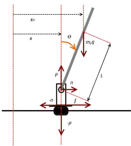
In order to simulate the pendulum behaviour, the well known, no friction, linearized under small deviations model was used. Considering Fig. 1, the following variables and parameters are defined:
– angular displacement of pendulum from vertical, positive clockwise;
x – displacement of cart from the reference point; xp – linear displacement of the centre of mass of
pendulum;
f – force on cart resulting from the DC motor; n and p – forces on the pendulum axis;
m – pendulum mass;
A Realization of the Inverted Pendulum and
Cart
L – distance from the centre of mass to the pendulum axis;
g – gravity acceleration;
The linearized state space vector Xis chosen as:
Tv x
X (1)
where v and are, respectively, the linear velocity of the cart and the angular velocity of pendulum. It is true that
v
x (2)
so that one has only to find the expression for the derivatives of v and . The derivative of the quantity of movement of the cart is given by:
n f v
M (3)
The xp displacement of the pendulum equals: )
( Lsen x
xp (4)
Given the small deviations approximation sen() , it becomes
L x
xp (5)
The expression for n can be written
(x L ) mv mL
dt d m x m
n p 2
2
(6)
From which one gets
f mL
v ) m M
( (7)
Now, the expression for the derivative of must be found. The derivative of the quantity of movement of the pendulum along the vertical is:
mg p )) cos( L ( dt d
m 2
2
(8)
Again, because is small, cos() 1, so one has
mg
p (9)
Therefore, we can write
) cos( nL ) ( pLsen
J (10)
Again, linearizing we get
nL mgL
J (11)
After some algebra, we finally get:
[image:2.595.311.542.51.307.2]f mM L ) m M ( J Lm mM L ) m M ( J m L J v x mM L ) m M ( J ) m M ( Lmg mM L ) m M ( J g ) Lm ( v x X 2 2 2 2 2 2 0 0 0 0 0 1 0 0 0 0 0 0 0 0 1 0 (12)
Fig. 1 – Diagram of forces for the cart and pendulum.
III. THE DEVELOPED PLATFORM
This section presents an overview of the developed platform, which is divided into the following subsystems:
Structure, to accommodate all the mechanical and electronic components;
Pendulum block, to provide support and angular position to the sensor of the pendulum;
Motor and encoder, to move and measure the position of the cart along the rail;
Controller, to equilibrate the pendulum by implementing the control algorithm under test. A. Structure
The structure subsystem accommodates all the mechanical and electronic components. Its main constituents are:
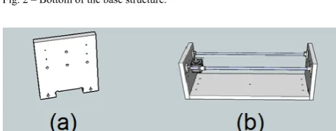
Base structure: It supports all the system components. It is composed of a bottom (Fig. 2 and Fig. 3), two lateral walls (Fig. 3) and two linear rails (Fig. 3). The bottom and the lateral walls were built using MDF and assembled with 3mm wooden pins. The linear rails are made of aluminium alloy.
Linear bearing block: This component was developed to serve as a case for the linear bearings. In this component two 3mm screw holes were also implemented for assembly with the tray (Fig. 4). Tray: This platform serves as support for all the
components of the pendulum support structure. Attached to the tray there are two linear bearing blocks, the support bearings for the pendulum, the potentiometer holder and the strap retainer (Fig. 5). Adjustable connector for pulley: This component
was designed to attach a pulley. It has a screw rail with 50mm for further belt tension adjustment (Fig. 6).
Fig. 2 – Bottom of the base structure.
[image:3.595.45.289.124.219.2]Fig. 3 – Wall of the base structure (a) and mechanical design of the whole base structure (b).
Fig. 4 – Linear bearing block.
Fig. 5 – Tray of the system.
[image:3.595.46.291.262.375.2]Fig. 6 - Adjustable connector for pulley.
Fig. 7 - Motor support.
B. Pendulum block
The pendulum support is used to keep the inverted pendulum free to move in one axis. Its main components are the following ones:
Potentiometer support: This component was designed to hold a potentiometer, which in turn serves as an angular positioning sensor of the pendulum. The docking zone was sized to be able to perform a subsequent adjustment of the potentiometer. Two screw holes allow fastening it to the tray (Fig. 8).
Pendulum bearing support: This component is a fitting for cylindrical bearings that, subsequently, engage to the pendulum fitting component. Initially, this component was designed to support only one bearing. After a first phase of testing, the component was resized in order to support two bearings. The usage of two bearings provides more stability to the pendulum-fitting component, reducing the impact of torsion stresses on the platform (Fig. 9).
Pendulum support: This component serves as the main pendulum support. It has a machined 8mm screw hole where the pendulum is screwed. The cylindrical opposite end fits into the cylindrical bearings in the pendulum bearing support, being engaged with the connector potentiometer-pendulum support (Fig. 10).
[image:3.595.307.547.466.581.2] Connector potentiometer-pendulum support: This component serves as the connector between the pendulum support and the angular positioning potentiometer. It was designed to avoid gaps and oscillations. The central screw hole is used to fit the pendulum support; the two side holes are used to fasten the potentiometer (Fig. 11).
[image:3.595.305.549.602.753.2]Fig. 8 - Potentiometer support.
[image:3.595.47.291.646.759.2]Fig. 10 - Pendulum support.
Fig. 11 - Connector potentiometer-pendulum support.
All the developed components were designed using CAD software and they were machined and built with 0.01 mm accuracy. All the mechanical components were built in aluminium alloy, except for the base structure (built in MDF) and the tray (built in PVC).
Different CAD software applications were used along the developing process since the authors were also testing the different capabilities and functionalities of different CAD software applications. It is worth mentioning that this is the reason for having different types of CAD drawings in this paper.
In order to obtain an accurate equilibrium, all the rotating components were free floating balanced. This is a necessity and an important step because it allows removing errors that may not be controllable or may cause the use of additional control methods or specific programming code targeting the unbalance.
C. Motor and Encoder
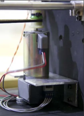
The following components were used in the platform: A 24V DC motor (Fig. 12) with an HP/Agilent
two-phase optical encoder, which allows determining the motor rotation direction by comparing the phase of two square waves;
A MD10C motor driver from Cytron Technologies (http://www.robotshop.com/media/files/pdf/user-manual-md10c-v2.pdf);
[image:4.595.44.291.50.231.2] An Arduino Mega used in the control of the system (http://arduino.cc/en/Main/arduinoBoardMega).
Fig. 12 – Motor detail.
D. Controller
Four operating zones were defined depending on the pendulum inclination:
Operation zone 1 – Angle > 10º Operation zone 2 – 5º < Angle < 10º Operation zone 3 – Angle > 5º Operation zone 4 – Angle < deadband
Operating zone 1 corresponds to an uncontrolled state. Since this platform is a modular training model for the implementation of different control strategies, three switches were added to the system, allowing the implementation of a real time parameterisation control for these operation zones (zone 2 to 4). In that way, the user can change the controller parameter values and observe the result without having to compile a new code in the controller every time it is necessary to test different parameters.
The Proportional, Integral and Derivative (PID) algorithm was implemented in the operation zones 2 and 3. The PID controller has 1) a proportional block that multiplies the error (difference between the reference signal and the output value) and the proportional gain; 2) an integral block that calculates the integral of the error; and 3) a differential block, responsible for the determination of the error derivative.
The continuous control signal, u(t), is defined as a function of the error, e(t) = signal reference r(t) – signal output y(t), by (13).
dt de K dt ) t ( e K ) t ( e K ) t (
u p i d (13)
where Kp is the proportional constant, Ki is the integral
constant and Kd is the derivative constant. The different
digital versions of the PID algorithm are available in [15]-[16].
Different aspects were taken into consideration when designing the controller:
[image:4.595.46.290.266.401.2] Gain-scheduled PID controller or runtime parameters update. Different PID values are used in this setup (operation zones 2 and 3). This allows for a finer control depending on the present angular state of the pendulum. Different angular states of the pendulum require different responses from the controller, demanding a quicker response from the motor driver, implying different Kp, Ki or Kd values
(Fig. 13);
Deadband. The deadband is an implemented parameter that defines the allowed natural state of balance (operation zone 4). On the platform there is a point in which the force of the main rotating bearing equals the force of gravity on the pendulum. Therefore, this parameter allows the system not to call the controller when the system finds balance within the programmed range.
Fig. 13 presents the control algorithm implemented showing the different operating regions considered.
IV. EXPERIMENTAL RESULTS
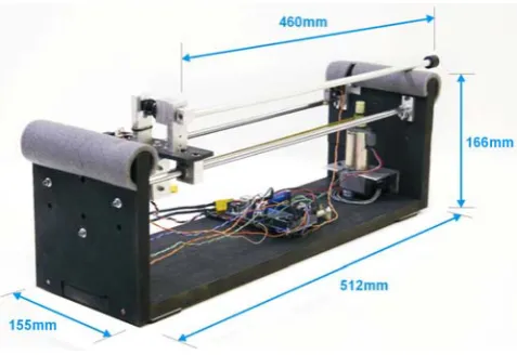
The final prototype is presented in Fig. 14. The platform weights 2569g, the pendulum has a length of 460mm with an outer diameter of 7.99mm and an inner diameter of 6mm. The maximum velocity of the cart is about 1.73m/s.
The PID algorithm was implemented for the two operating zones. The controller gains were tuned by trial and error. For the operating zone 2 (5º < angle < 10º), PID1 in Fig. 13 has the following gains: Kp=2, Ki=0.1, Kd=0.01.
In the operating zone 3 (angle < 5º), PID2 in Fig. 13, the following gains were implemented: Kp=30, Ki=0, Kd=0.
[image:5.595.306.545.49.213.2]A deadband value of ±2º was tuned experimentally. A video showing the platform performance during a running test is available here: https://uminho365-my.sharepoint.com/personal/a53991_uminho_pt/_layouts/15 /guestaccess.aspx?guestaccesstoken=%2b9wjJ%2ftryZlPshP EAKUox2EJs5eaQdZXOQNth51iR1U%3d&docid=0c89eb 3a86dde4b7c9b87d5547e11da7d.
Fig. 13 – Control Algorithm.
Fig. 14 – The final platform.
V. CONCLUSIONS
This paper described the design and implementation of an inverted pendulum control system, its mechanical conception and CAD drawings, as well as the implemented hardware and the control laws applied. The generic PID controller was successfully implemented and some concerns were taken into consideration such as the update rate of the control loop, the definition of different operating zones with different PID parameters, the runtime update and also the deadband in order to define the range for sustaining equilibrium. Some results were shown and the implemented system was tested with success in different situations.
REFERENCES
[1] R. P. M. Chan, K. A. Stol, and C. R. Halkyard, Review of modelling
and control of two-wheeled robots, Annual Reviews in Control,vol.
37, pp. 89–103, 2013.
[2] R. Bansevicius, A. Lipnickas, V. Juska, and V. Raudonis, Piezoelectric Inverted Pendulum as a Teaching Aid for Mechatronics
Courses, IEEE International Workshop on Intelligent Data
Acquisition and Advanced Computing Systems: Technology and Applications, 21-23 September 2009, Rende (Cosenza), Italy. [3] G. Figueroa-Flores, A. Leal-Naranjo, C. R. Torres-San Miguel, G.
Urriolagoitia-Sosa, and G. Urriolagoitia-Calderón, Implementation of an Intelligent Controller into a Robotic Device for Rehabilitation
Intended for Lower Extremity Paralysis Patients, Journal of
Chemical, Biological and Physical Sciences, special Issue, Section C; 30 Nov Vol. 4, No. 5, pp. 5-17, 2014.
[4] J. Han, X. Li, and Q. Qin, Design of Two-Wheeled Self-Balancing
Robot Based on Sensor Fusion Algorithm, Int. J. of Automation
Technology, Vol.8, No.2, 2014.
[5] L. Sun and J. Gan, Researching of Two-Wheeled Self-Balancing
Robot Base on LQR Combined with PID, 2nd International Workshop
on Intelligent Systems and Applications (ISA), 22-23 May, Wuhan, 2010.
[6] H. Juang and K. Lum, Design and Control of a Two-Wheel
Self-Balancing Robot using the Arduino Microcontroller Board, 10th
IEEE International Conference on Control and Automation (ICCA), Hangzhou, China, June 12-14, 2013.
[7] J. Hua, Y. Cui, P. Shi, Y. Yang, and H. Li, Force Feedback Assisted
Balancing of Inverted Pendulum under Manual Control, Fourth
International Conference on Intelligent Control and Information Processing (ICICIP), June 9 – 11, Beijing, China, 2013.
[8] W. An and Y. Li, Simulation and Control of a Two-wheeled
Self-balancing Robot, Proceeding of the IEEE International Conference on
Robotics and Biomimetics (ROBIO), Shenzhen, China, Dec. 2013. [9] H. Vasudevan, A. M. Dollar, and J.B. Morrell, Design for control of
wheeled inverted pendulum platforms, Journal of Mechanisms and
Robotics, November 2015, Volume 7, Issue 4, 2015.
[10] O. O. Rodríguez, H. E. Cely., and J. A. Riaño, Design and implementation of an inverted pendulum on a cart applying control
[image:5.595.52.294.545.760.2]Avanzada, Universidad de Pamplona, vol 1, n 19, 2012, ISBN 1692-7257.
[11] Googol Technology, Inverted Pendulum – Experimental Manual,
Suitable for Glip Series, Second Edition, July, 2006,
http://www.googoltech.com.cn/webtech_en/products/files/161_linear %2002.pdf, accessed in January 2015.
[12] IIEE Visionaries, Inverted Pendulum Analysis, design and
Implementation, Document version 1.0, 2003
http://www.engr.usask.ca/classes/ee/480/inverted%20pendulum.pdf, accessed in January 2015.
[13] J. Jie and T. Wei, “Influence Analysis of Initial State Parameters on Linear Inverted Pendulum System Performance”, presented at 24th Chinese Control and Decision Conference (CCDC), 2012, pp. 3498 – 3501, DOI: 10.1109/CCDC.2012.6244558.
[14] Md. Akhtaruzzaman and A. A. Shafie, “Modeling and Control of a Rotary Inverted Pendulum Using Various Methods, Comparative Assessment and Result Analysis” in Proceedings of the 2010 IEEE International Conference on Mechatronics and Automation 2010, DOI: 10.1109/ICMA.2010.5589450.
[15] K. Astrom and B. Wittenmark, Computer-Controlled Systems –
Theory and Design, 3rd Edition, Prentice Hall, New Jersey, 1996.
[16] K. Astrom and T. Hagglund, PID controllers: Theory, Design and