Part No. 118353-A Rev. A September 1997
All rights reserved. Printed in the USA. September 1997.
The information in this document is subject to change without notice. The statements, configurations, technical data, and recommendations in this document are believed to be accurate and reliable, but are presented without express or implied warranty. Users must take full responsibility for their applications of any products specified in this document. The information in this document is proprietary to Bay Networks, Inc.
The software described in this document is furnished under a license agreement and may only be used in accordance with the terms of that license. A summary of the Software License is included in this document.
Trademarks
Bay Networks is a registered trademark and Remote Annex, BayStack,
Quick2Config, System 5000, Bay Networks Press, and the Bay Networks logo are trademarks of Bay Networks, Inc.
Microsoft, MS, MS-DOS, Win32, Windows, and Windows NT are registered trademarks of Microsoft Corporation.
All other trademarks and registered trademarks are the property of their respective owners.
Restricted Rights Legend
Use, duplication, or disclosure by the United States Government is subject to restrictions as set forth in subparagraph (c)(1)(ii) of the Rights in Technical Data and Computer Software clause at DFARS 252.227-7013.
Notwithstanding any other license agreement that may pertain to, or accompany the delivery of, this computer software, the rights of the United States Government regarding its use, reproduction, and disclosure are as set forth in the Commercial Computer Software-Restricted Rights clause at FAR 52.227-19.
Statement of Conditions
In the interest of improving internal design, operational function, and/or reliability, Bay Networks, Inc. reserves the right to make changes to the products described in this document without notice.
Class A digital device, pursuant to
application of Council Directive 89/336/EEC, Article 4a. Conformity is declared by the application of EN 55 022 Class A (CISPR 22).
Warning: This is a Class A product. In a domestic environment, this product may cause radio interference, in which case, the user may be required to take
appropriate measures.
EC Declaration of Conformity
Voluntary Control Council for Interference (VCCI) Statement
the Class A limits for radio-noise emissions from digital apparatus as set out in the Radio Interference Regulations of the Canadian Department of Communications.
Règlement sur le brouillage radioélectrique du ministère des Communi-cations
Cet appareil numérique (Model 8000 Remote Access Concentrator) respecte les limites de bruits radioélectriques visant les appareils numériques de classe A prescrites dans le Règlement sur le brouillage radioélectrique du ministère des Communications du Canada.
Canada CS-03 Rules and Regulations
Note: The Canadian Department of Communications label identifies certified equipment. The certification means that the equipment meets certain
telecommunications network protective, operational and safety requirements. The Department does not guarantee the equipment will operate to the user’s
satisfaction.
Before installing this equipment, users should ensure that it is permissible to be connected to the facilities of the local telecommunications company. The equipment must also be installed using an acceptable method of connection. In some cases, the company’s inside wiring associated with a single line individual service may be extended by means of a certified connector assembly (telephone extension cord). The customer should be aware that compliance with the above conditions may not prevent the degradation of service in some situations. Repairs to certified equipment should be made by a representative designated by the supplier. Any repairs or alterations made by the user to this equipment, or equipment malfunctions, may give the telecommunications company cause to request the user to disconnect the equipment.
Users should ensure for their own protection that the electrical ground connections of the power utility, telephone lines and internal metallic water pipe system, if present, are connected together. This precaution may be particularly important in rural areas.
Caution: Users should not attempt to make such connections themselves, but should contact the appropriate electric inspection authority, or electrician, as appropriate.
Notice: For equipment using loopstart lines, please note that the Ringer Equivalence Number (REN) assigned to each terminal device provides an indication of the maximum number of terminals allowed to be connected to a telephone interface. The termination on an interface may consist of any
combination of devices subject only to the requirement that the sum of the RENs of all the devices does not exceed 5.0. The REN is located on the “FCC Rules Part 68” label located on the bracket of the module, or on the back of the unit.
Canada CS-03 -- Règles et règlements
prendre note qu’une telle installation n’assure pas un service parfait en tout temps. Les réparations de l’appareillage certifié devraient être confiées à un service désigné par le fournisseur. En cas de réparation ou de modification effectuées par l’utilisateur ou de mauvais fonctionnement de l’appareillage, le service de télécommunications peut demander le débranchement de l’appareillage.
Pour leur propre sécurité, les utilisateurs devraient s’assurer que les mises à la terre des lignes de distribution d’électricité, des lignes téléphoniques et de la tuyauterie métallique interne sont raccordées ensemble. Cette mesure de sécurité est particulièrement importante en milieu rural.
Attention: Les utilisateurs ne doivent pas procéder à ces raccordements eux-mêmes mais doivent plutôt faire appel aux pouvoirs de réglementation en cause ou à un électricien, selon le cas.
1. You are required to request service from the telephone company before you connect the unit to a network. When you request service, you must provide the telephone company with the following data:
• When you request T1 Service, you must provide the telephone company with
-- The Facility Interface Code
Provide the telephone company with all the codes below: - 04DU9-BN (1.544 MB, D4 framing format)
- 04DU9-DN (1.544 MB, D4 framing format with B8ZF coding)
- 04DU9-1KN (1.544 MB, ESF framing format)
- 04DU9-1SN (1.544 MB, ESF framing format with B8ZF coding)
- 04DU9-1ZN (1.544 MB, ANSI ESF and ZBTSI without line power)
The telephone company will select the code it has available. -- The Service Order Code(s) (SOC): 6.0Y
-- The required Universal Service Order Code (USOC) jack: RJ48C • When you request ISDN “U” Interface Service, you must provide the
telephone company with
-- The Facility Interface Code: 02IS5 -- The Service Order Code(s) (SOC): 6.0F
-- The required Universal Service Order Code (USOC) jack: RJ49C • When you request ISDN “S/T” Interface Service, you must provide the
telephone company with
-- The Service Order Code(s) (SOC): 6.0P
-- The make, model number, and FCC Registration number of the NT1
Note: ISDN S/T cannot be directly connected to the network.
• When you request Primary Rate ISDN Service, you must provide the telephone company with
-- The Facility Interface Code: 04DU9-1SN (1.544 MB, ESF framing format with B8ZF coding)
-- The Service Order Code(s) (SOC): 6.0Y
-- The required Universal Service Order Code (USOC) jack: RJ48C 2. Your telephone company may make changes to its facilities, equipment,
Technical Solutions Center in your area for service or repairs. Repairs should be performed only by service personnel authorized by Bay Networks, Inc.
6. Your telephone company may make changes to its facilities, equipment, operations, or procedures that could affect the proper functioning of your equipment. The telephone company will notify you in advance of such changes to give you an opportunity to maintain uninterrupted telephone service.
7. If the unit causes harm to the telephone network, the telephone company may temporarily discontinue your service. If possible, they will notify you in advance, but if advance notice is not practical, you will be notified as soon as possible and will be informed of your right to file a complaint with the FCC. 8. If you experience trouble with the unit, please contact the Bay Networks
Technical Solutions Center in your area for service or repairs. Repairs should be performed only by service personnel authorized by Bay Networks, Inc.
United States 1-800-2LAN-WAN Valbonne, France 33-4-92-96-69-68 Sydney, Australia 61-2-9927-8800 Tokyo, Japan 81-3-5402-0180
CONDITIONS OF THIS LICENSE AGREEMENT. THE TERMS EXPRESSED IN THIS AGREEMENT ARE THE ONLY TERMS UNDER WHICH BAY NETWORKS WILL PERMIT YOU TO USE THE SOFTWARE. If you do not accept these terms and conditions, return the product, unused and in the original shipping container, within 30 days of purchase to obtain a credit for the full purchase price.
1. License Grant. Bay Networks, Inc. (“Bay Networks”) grants the end user of the Software (“Licensee”) a personal, nonexclusive, nontransferable license: a) to use the Software either on a single computer or, if applicable, on a single authorized device identified by host ID, for which it was originally acquired; b) to copy the Software solely for backup purposes in support of authorized use of the Software; and c) to use and copy the associated user manual solely in support of authorized use of the Software by Licensee. This license applies to the Software only and does not extend to Bay Networks Agent software or other Bay Networks software products. Bay Networks Agent software or other Bay Networks software products are licensed for use under the terms of the applicable Bay Networks, Inc. Software License Agreement that accompanies such software and upon payment by the end user of the applicable license fees for such software.
2. Restrictions on use; reservation of rights. The Software and user manuals are protected under copyright laws. Bay Networks and/or its licensors retain all title and ownership in both the Software and user manuals, including any revisions made by Bay Networks or its licensors. The copyright notice must be reproduced and included with any copy of any portion of the Software or user manuals. Licensee may not modify, translate, decompile, disassemble, use for any competitive analysis, reverse engineer, distribute, or create derivative works from the Software or user manuals or any copy, in whole or in part. Except as expressly provided in this Agreement, Licensee may not copy or transfer the Software or user manuals, in whole or in part. The Software and user manuals embody Bay Networks’ and its licensors’ confidential and proprietary intellectual property. Licensee shall not sublicense, assign, or otherwise disclose to any third party the Software, or any information about the operation, design, performance, or implementation of the Software and user manuals that is confidential to Bay Networks and its licensors; however, Licensee may grant permission to its consultants, subcontractors, and agents to use the Software at Licensee’s facility, provided they have agreed to use the Software only in accordance with the terms of this license.
Licensee assumes all responsibility for selection of the Software to achieve Licensee’s intended results and for the installation, use, and results obtained from the Software. Bay Networks does not warrant a) that the functions contained in the software will meet the Licensee’s requirements, b) that the Software will operate in the hardware or software combinations that the Licensee may select, c) that the operation of the Software will be uninterrupted or error free, or d) that all defects in the operation of the Software will be corrected. Bay Networks is not obligated to remedy any Software defect that cannot be reproduced with the latest Software release. These warranties do not apply to the Software if it has been (i) altered, except by Bay Networks or in accordance with its instructions; (ii) used in conjunction with another vendor’s product, resulting in the defect; or (iii) damaged by improper environment, abuse, misuse, accident, or negligence. THE
FOREGOING WARRANTIES AND LIMITATIONS ARE EXCLUSIVE REMEDIES AND ARE IN LIEU OF ALL OTHER WARRANTIES EXPRESS OR IMPLIED, INCLUDING WITHOUT LIMITATION ANY WARRANTY OF MERCHANTABILITY OR FITNESS FOR A PARTICULAR PURPOSE. Licensee is responsible for the security of its own data and information and for maintaining adequate procedures apart from the Software to reconstruct lost or altered files, data, or programs.
4. Limitation of liability. IN NO EVENT WILL BAY NETWORKS OR ITS LICENSORS BE LIABLE FOR ANY COST OF SUBSTITUTE
PROCUREMENT; SPECIAL, INDIRECT, INCIDENTAL, OR
CONSEQUENTIAL DAMAGES; OR ANY DAMAGES RESULTING FROM INACCURATE OR LOST DATA OR LOSS OF USE OR PROFITS ARISING OUT OF OR IN CONNECTION WITH THE PERFORMANCE OF THE SOFTWARE, EVEN IF BAY NETWORKS HAS BEEN ADVISED OF THE POSSIBILITY OF SUCH DAMAGES. IN NO EVENT SHALL THE LIABILITY OF BAY NETWORKS RELATING TO THE SOFTWARE OR THIS
AGREEMENT EXCEED THE PRICE PAID TO BAY NETWORKS FOR THE SOFTWARE LICENSE.
5. Government Licensees. This provision applies to all Software and
documentation acquired directly or indirectly by or on behalf of the United States Government. The Software and documentation are commercial products, licensed on the open market at market prices, and were developed entirely at private expense and without the use of any U.S. Government funds. The license to the U.S. Government is granted only with restricted rights, and use, duplication, or disclosure by the U.S. Government is subject to the restrictions set forth in subparagraph (c)(1) of the Commercial Computer Software––Restricted Rights clause of FAR 52.227-19 and the limitations set out in this license for civilian agencies, and subparagraph (c)(1)(ii) of the Rights in Technical Data and Computer Software clause of DFARS 252.227-7013, for agencies of the Department of Defense or their successors, whichever is applicable.
user manuals will cease being effective at the date of expiration of the Bay Networks copyright; those restrictions relating to use and disclosure of Bay Networks’ confidential information shall continue in effect. Licensee may terminate this license at any time. The license will automatically terminate if Licensee fails to comply with any of the terms and conditions of the license. Upon termination for any reason, Licensee will immediately destroy or return to Bay Networks the Software, user manuals, and all copies. Bay Networks is not liable to Licensee for damages in any form solely by reason of the termination of this license.
8. Export and Re-export. Licensee agrees not to export, directly or indirectly, the Software or related technical data or information without first obtaining any required export licenses or other governmental approvals. Without limiting the foregoing, Licensee, on behalf of itself and its subsidiaries and affiliates, agrees that it will not, without first obtaining all export licenses and approvals required by the U.S. Government: (i) export, re-export, transfer, or divert any such Software or technical data, or any direct product thereof, to any country to which such exports or re-exports are restricted or embargoed under United States export control laws and regulations, or to any national or resident of such restricted or embargoed countries; or (ii) provide the Software or related technical data or information to any military end user or for any military end use, including the design,
development, or production of any chemical, nuclear, or biological weapons. 9. General. If any provision of this Agreement is held to be invalid or
unenforceable by a court of competent jurisdiction, the remainder of the provisions of this Agreement shall remain in full force and effect. This Agreement will be governed by the laws of the state of California.
Should you have any questions concerning this Agreement, contact Bay Networks, Inc., 4401 Great America Parkway, P.O. Box 58185, Santa Clara, California 95054-8185.
Revision Description
Conventions . . . xxiv
Acronyms . . . xxv
Ordering Bay Networks Publications . . . xxvi
Bay Networks Customer Service . . . xxvi
How to Get Help . . . xxvii
Chapter 1 Introduction
Model 8000 Remote Access Concentrator Description . . . 1-3 Main Logic Board . . . 1-4 Modem Cards . . . 1-4 Compression Controller . . . 1-5 Firmware and Software. . . 1-5 Front Panel . . . 1-7 Front Panel Components . . . 1-8 Rear Panel . . . 1-11 Physical Characteristics . . . 1-13
Chapter 2
Installing the Model 8000 Remote Access Concentrator
Command Descriptions . . . 3-2 addr. . . 3-4 allow_snmp_sets . . . 3-7 boot . . . 3-8 config . . . 3-14 erase . . . 3-15 help . . . 3-16 image . . . 3-17 lat_key . . . 3-18 net . . . 3-19 ping . . . 3-20 ports . . . 3-21 sequence . . . 3-22 stats . . . 3-24
Chapter 4
Troubleshooting Procedures
Front-Panel Alarms and LED Indicators . . . 4-1 Power-Up and Boot Procedures. . . 4-4 Normal Mode Diagnostics. . . 4-4 Setup Mode . . . 4-7 Boot Failures . . . 4-10 Boot Error Report . . . 4-11 Correcting Remote Access Concentrator Parameters . . . 4-13 Load Server Host Not Responding . . . 4-14 Remote Access Concentrator Dumps . . . 4-19
Appendix A
Port Pins and Signals
Console Port. . . A-1 WAN Interface Ports. . . A-2 10BASE-T Ethernet Port . . . A-3 AUI Ethernet Port . . . A-4 Sync Port . . . A-6
Appendix B
Modem Upgrade Instructions
Contents of the Kit . . . C-1 Required Tools . . . C-1 Removing the RAC Cover . . . C-2 Installing the Compression Card. . . C-3 Replacing the RAC Cover. . . C-4
Table 1-2. Status and Alarm LEDs . . . 1-10
Table 2-1. Server Parameters . . . 2-16
Table 3-1. ROM Monitor Commands. . . 3-2
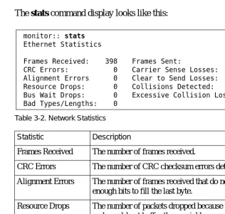
Table 3-2. Network Statistics . . . 3-24
Table 4-1. Model 8000 RAC Front-Panel LEDs . . . 4-2
Table 4-2. Normal Mode Error-free LED States . . . 4-5
Table 4-3. Normal Mode Error LED States . . . 4-6
Table 4-4. Setup Mode Error LED States . . . 4-7
Table 4-5. Setup Mode Error LED States . . . 4-8
Table 4-6. Errors from Last ERPC Layer Invocation . . . 4-12
Table 4-7. Errors from Last Read Request . . . 4-12
Table 4-8. Errors from Last Open Request . . . 4-13
Table 4-9. Remote Access Concentrator LED States During a Dump . . . 4-19
Table 4-10. Remote Access Concentrator Dump File Naming Conventions . . . 4-21
Table A-1. Console Port Pin/Signal Allocations. . . A-2
Table A-2. WAN Interface Port/Pin Signal Allocations . . . A-3
Table A-3. 10BASE-T Ethernet Port Pin/Signal Allocations . . . A-4
Table A-4. AUI Ethernet Port Pin/Signal Allocations . . . A-5
T
his manual describes how to install a Model 8000 Remote Access Concentrator. For brevity, this manual often uses the acronym RAC to refer to the Remote Access Concentrator.Refer to Installing Remote Access Concentrator Software for UNIX or
Installing Remote Access Concentrator Software for Windows and
Windows NT® for a description of the software installation. Refer to
Managing Remote Access Concentrators Using Command Line Interfaces for configuration information.
If you want Go to
An overview of the Model 8000 Remote Access Concentrator, including a description of the hardware features and firmware functions
Chapter 1
Instructions for installing the RAC and confirming its operating status
Chapter 2
A description the ROM Monitor commands that modify specific configuration parameters, perform diagnostic tests, and load the operational code
Chapter 3
Troubleshooting and verification procedures Chapter 4
A description of the port connectors located on the RAC Appendix A
Instructions for installing and removing modem cards on the RAC main logic board
Appendix B
Instructions for installing the data compression card on the RAC main logic board
Conventions
This manual uses the following printing conventions:
Convention: Represents:
special type In examples,special type indicates system output.
special type Boldspecial type indicates user input.
In command examples, this notation indicates that pressing enters the default value.
bold Bold indicates commands, pathnames, or filenames that must be entered as displayed.
italics In the context of commands and command syntax,
lowercase italics indicate variables for which the user supplies a value.
[ ] In command dialog, square brackets indicate default values. Pressing selects this value. Square brackets appearing in command syntax indicate optional
arguments.
{ } In command syntax, braces indicate that one, and only one, of the enclosed value must be entered.
| In command syntax, this character separates the different options available for a parameter.
Notes provide important information.
Warnings inform you about conditions that can have adverse effects on processing.
Cautions notify you about dangerous conditions. Return
Return
Acronyms
AFD Automatic Firmware Download
ARP Address Resolution Protocol
AUI Attachment Unit Interface
BFS Boot File System
BootP Bootstrap Protocol
BRI Basic Rate Interface
CLI Command Line Interface
CSU Channel Service Unit
Erpcd Expedited remote procedure call daemon
IP Internet Protocol
ISDN Integrated Services Digital Network
ISO International Organization for Standardization
LAN Local Area Network
LAT Local Area Transport
MAU Media Access Unit
MLB Main Logic Board
PPP Point-to-Point Protocol
PRI Primary Rate Interface
RAC Remote Access Concentrator
RARP Reverse Address Resolution Protocol
SLIP Serial Line Interface Protocol
SNMP Simple Network Management Protocol
TCP/IP Transmission Control Protocol/Internet Protocol
Telnet Telecommunication Network
TFTP Trivial File Transfer Protocol
TPE Twisted-Pair Ethernet
UDP Unreliable Datagram Protocol
Ordering Bay Networks Publications
To purchase additional copies of this document or other Bay Networks publications, order by part number from Bay Networks Press™ at the
following numbers:
• Phone--U.S./Canada: 888-422-9773
• Phone--International: 510-490-4752
• FAX--U.S./Canada and International: 510-498-2609
The Bay Networks Press catalog is available on the World Wide Web at support.baynetworks.com/Library/GenMisc. Bay Networks publications are available on the World Wide Web at support.baynetworks.com/Library/tpubs.
Bay Networks Customer Service
You can purchase a support contract from your Bay Networks distributor or authorized reseller, or directly from Bay Networks Services. For information about, or to purchase a Bay Networks service contract, either call your local Bay Networks field sales office or one of the following numbers:
Information about customer service is also available on the World Wide Web at support.baynetworks.com.
Region Telephone number Fax number
United States and Canada
800-2LANWAN; then enter Express Routing Code (ERC) 290, when prompted, to purchase or renew a service contract
508-916-8880 (direct)
508-916-3514
Europe 33-4-92-96-69-66 33-4-92-96-69-96
Asia/Pacific 61-2-9927-8888 61-2-9927-8899
How to Get Help
If you purchased a service contract for your Bay Networks product from a distributor or authorized reseller, contact the technical support staff for that distributor or reseller for assistance.
If you purchased a Bay Networks service program, call one of the following Bay Networks Technical Solutions Centers:
Technical Solutions Center Telephone number Fax number Billerica, MA 800-2LANWAN 508-916-3514
Santa Clara, CA 800-2LANWAN 408-495-1188
Valbonne, France 33-4-92-96-69-68 33-4-92-96-69-98
Sydney, Australia 61-2-9927-8800 61-2-9927-8811
T
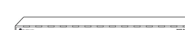
he Model 8000 Remote Access Concentrator (RAC) is a dial-in remote access server that supports mixed traffic, such as analog modems, V.120 ISDN terminal adapters, and devices supporting synchronous PPP.Figure 1-1 illustrates a Model 8000 Remote Access Concentrator.
Figure 1-1. Model 8000 Remote Access Concentrator
RA0001A
8000 Remote Access Concentrator
WAN 1 WAN 2 LAN/Unit
Status
Status Alarms Channel Activity
% Utilization Test Red Sync Yel LOS Blu 20 40 60 80 100 FULL 20 40 60 80 100 FULL
Status Alarms Channel Activity
% Utilization Test Red Sync Yel
Sync Setup Power Stat Reset Traf
Remote Network Access
The RAC provides remote network access to the following networks (Figure 1-2):
• TCP/IP
• Novell Netware
[image:32.612.164.471.111.499.2]• AppleTalk
Figure 1-2. Model 8000 RAC as a Remote Access Server DEC
Model 8000 Remote Access Concentrator Apple
Macintosh IBM UNIX
Ethernet Corporate LAN
Novell Server
Central Office Channelized T1, Channelized E1 or
PRI ISDN Lines
Up to 60 Analog, V.120, or Synchronous PPP Lines 8000 Remote Access Concentrator
The RAC also provides terminal-to-host connectivity to the following:
• UNIX hosts (using TCP/IP)
• VMS hosts (using LAT)
• IBM hosts (using TN3270)
Model 8000 Remote Access Concentrator Description
The Model 8000 RAC is a wide area network server capable of supporting domestic ISDN, European ISDN, channelized T1, and channelized E1. The Model 8000 RAC can house up to 62 modems to provide the flexibility of terminating calls originated by analog modems, terminal adapters, and routers.
The RAC consists of the following:
• Main logic board
• Digital modem cards
• Compression/decompression daughter card (optional) The RAC supports Windows NT® host tools. Remote Access Server Tools allow you to boot and configure the RAC on a Windows NT network. For more information, refer to Using
Main Logic Board
Processors The Model 8000 RAC uses three 80486 DX2 clock-doubled processors,
operating at 64 MHz.
WAN Interfaces Two WAN interfaces reside on the MLB and are accessible via RJ-48C
connectors on the rear panel. Each WAN interface is controlled by one of the 80486 DX2 processors, which also controls the internal modems. The WAN interfaces can accept channelized T1, channelized E1, or ISDN PRI lines.
Ethernet Interfaces The MLB provides AUI (for thick or thin Ethernet) and 10BASE-T (for
twisted pair) autosensed Ethernet interfaces, accessible via connectors on the rear panel.
Sync Port The MLB provides one synchronous port that can support V.35, X.21,
RS-422, and RS-232 physical interfaces, which are accessible through a connector on the rear panel.
Memory The MLB is equipped with 8 megabytes (MB) of main DRAM. An
additional 4 MB of DRAM is provided for each WAN interface controller.
Flash Memory The MLB is equipped with 4 MB of flash memory for image storage.
Modem Cards
Digital Modems The RAC can be configured with up to 62 internal DSP-based digital
Compression Controller
Stac 9711 Coprocessor
The Model 8000 RAC supports an optional compression/decompression daughter card that utilizes the Stac 9711 coprocessor to implement high-speed LZS and MPPC.
Firmware and Software
Firmware The RAC ROM contains firmware for performing power-up self-tests and
loading operational code. A nonvolatile EEPROM stores the configuration parameters.
The RAC can boot from the boot image in its flash memory or can boot an image received from a boot server on the network.
ROM Monitor The ROM monitor is an interactive command interpreter that is used to
define basic configuration parameter values. You define the information that the Model 8000 RAC needs to boot an operational image using the ROM monitor and its command set. ROM monitor commands are issued from a terminal connected to the console port on the rear panel. When the RAC completes its self-tests, the console terminal displays the ROM monitor prompt. Using the ROM Monitor commands (see Chapter 3), you can:
• Modify and display a set of configuration parameters stored in EEPROM.
• Execute interactive diagnostic tests.
• Receive information and statistics for the hardware configuration and the network.
After the RAC obtains a boot image and is booted, it displays the Console monitor (for more details, see Chapter 2).
Supported Configurations
The Model 8000 RAC can self-boot from the image contained in its flash memory. The RAC can also obtain full operational code over the network from one of the following devices:
• UNIX host
• Another Model 8000 Remote Access Concentrator configured as a load server
• NT host
Watchdog Timer The Model 8000 RAC uses a watchdog timer that is reset by the software
Front Panel
The Model 8000 RAC front panel consists of:
• LAN/Unit Status LEDs
• Sync LED
• Reset button
• WAN 1 Status and Alarm LEDs
• WAN 1 Channel Activity LEDs
• WAN 2 Status and Alarm LEDs
[image:37.612.182.379.344.542.2]• WAN 2 Channel Activity LEDs
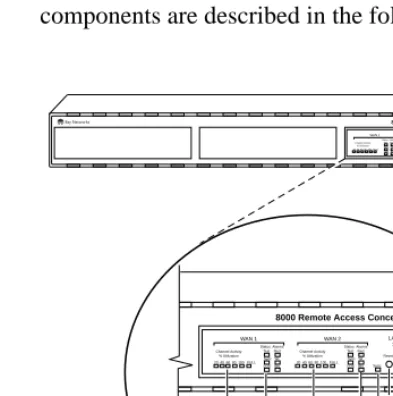
Figure 1-3 illustrates the Model 8000 RAC front panel. The front panel components are described in the following paragraphs.
Figure 1-3. Model 8000 Remote Access Concentrator Front Panel RA0024A
8000 Remote Access Concentrator
WAN 1 WAN 2 LAN/Unit Status
Status Alarms Channel Activity % Utilization
Test Red Sync Yel LOS Blu 20 40 60 80 100 FULL 20 40 60 80 100 FULL
Status Alarms Channel Activity
% Utilization Test Red Sync Yel
Sync Setup Power Stat Resest Traf
Attn
LOS Blu
8000 Remote Access Concentrator
WAN 1 WAN 2 LAN/Unit
Status
Status Alarms Channel Activity
% Utilization Test Red Sync Yel LOS Blu
Status Alarms Channel Activity
% Utilization Test Red Sync Yel
Sync Setup Power Stat Reset Traf
Attn LOS Blu 20 40 60 80 100 FULL 20 40 60 80 100 FULL
WAN 1 Channel Activity LEDs Sync LED Reset button WAN 1 Status and Alarm
LEDs WAN 2 Channel Activity
LEDs
WAN 2 Status and Alarm
LEDs LAN/Unit
Front Panel Components
LAN/Unit Status LEDs
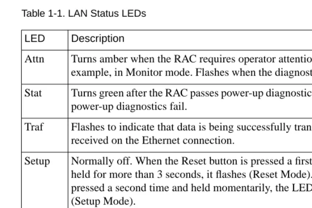
[image:38.612.160.477.179.390.2]The LAN/Unit Status LEDs display the status of the activity of the Model 8000 RAC (Table 1-1).
Table 1-1. LAN Status LEDs
Sync LED The Sync LED turns on and off corresponding to data activity on the
rear-panel Sync port. LED Description
Attn Turns amber when the RAC requires operator attention, for example, in Monitor mode. Flashes when the diagnostic tests fail.
Stat Turns green after the RAC passes power-up diagnostics. Flashes if power-up diagnostics fail.
Traf Flashes to indicate that data is being successfully transmitted or received on the Ethernet connection.
Setup Normally off. When the Reset button is pressed a first time and held for more than 3 seconds, it flashes (Reset Mode). When pressed a second time and held momentarily, the LED stays on (Setup Mode).
Reset Button You use the Reset button to:
• Enter Setup mode
When you press the Reset button, the RAC enters Setup mode and lights the amber Setup LED. In this mode, you can enter configuration data at the monitor:: prompt using the Console terminal, before booting the operational software.
• Reset the RAC
When you press the Reset button and hold it for 3 seconds, the Stat LED flashes and the RAC begins to execute its power-up diagnostics. If you press the Reset button again within 5 to 10 seconds, the RAC enters Setup mode and waits for configuration information to be entered.
Status and Alarm LEDs
Table 1-2. Status and Alarm LEDs
Channel Activity LEDs
The green Channel Activity LEDs labelled 20, 40, 60, 80, and 100, indicate the approximate percentage of B channels that are being used. The amber Channel Activity LED labelled Full indicates that all available B channels are in use. The Full LED stays on until at least one call disconnects. (By contrast, the LED labelled 100 indicates that between 80% and 100% of the channels are active.) There are two sets of Channel Activity LEDs, one set for each WAN port.
Alarm Description
TEST The network TEST indicator is on when the WAN Interface is looped back. Loopback tests are activated either locally by the user during diagnostics or by the telephone company.
SYNC The SYNC indicator is on when the WAN interface is properly synchronized with the received network signal and is receiving proper framing information. The absence of sync causes the RAC to transmit a YELLOW alarm across the telephone network.
LOS The LOS indicator is on when the WAN interface is detecting no signal on the network interface receiver. When an LOS condition exists, the RAC transmits a YELLOW alarm to the remote system.
RED The RED alarm indicator is on during a locally detected carrier failure such as loss of signal or loss of frame sync. During the RED alarm condition, a YELLOW alarm is transmitted across the telephone network.
YELLOW The YELLOW alarm indicator is on when receiving a YELLOW alarm condition from the telephone network. This indicates a failure detected at the other end of the link (the central office).
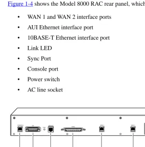
Rear Panel
Figure 1-4 shows the Model 8000 RAC rear panel, which consists of:
• WAN 1 and WAN 2 interface ports
• AUI Ethernet interface port
• 10BASE-T Ethernet interface port
• Link LED
• Sync Port
• Console port
• Power switch
• AC line socket
Figure 1-4. Model 8000 Remote Access Concentrator Rear Panel
RA0002A
CONSOLE 10BASET WAN 1
SYNC
AUI WAN 2
LINK
Console port
Sync port Ethernet
ports
WAN interface ports
AC line socket
Power switch
WAN Interface Ports The two WAN interface ports provide access to channelized T1, channelized E1, and ISDN PRI lines. The WAN Interface ports come with 8-pin, RJ-48C jacks for attaching T1, E1 or ISDN cable connectors.
Ethernet Ports The Model 8000 RAC provides autosensed AUI (Attachment Unit
Interface) and 10BASE-T Ethernet ports to connect the unit to the LAN. The AUI port allows connection of either 10BASE5 (thick Ethernet) or 10BASE2 (thin Ethernet), if you supply the appropriate transceiver. The AUI port accommodates most standard tranceivers, also known as Media Access Units (MAUs).
Link LED The Link LED is an Ethernet link layer integrity indicator. The LED is
on when an active 10BASE-T segment is attached, and off when an AUI segment is attached.
Sync Port The Sync port is used for trafficking data over several physical interface
types such as X.21, V.35, RS-422, and synchronous RS-232.
Console Port The Model 8000 RAC has a 9600-baud console port with an 8-pin,
Physical Characteristics
The Model 8000 RAC has the following characteristics:
• Dimensions:
Height: 2.6 in. (6.5 cm) Width: 19 in. (47.5 cm) Depth: 16.75 in. (41.9 cm)
• Weight:
20 lbs (9 kg)
• Electrical Specifications:
• Power consumption: 125 W
• Thermal rating: 427 Btu/hr maximum
• Environment:
• Operating temperature: 5° to 40°C
• Non-operating temperature: -25° to 65°C
• Operating humidity: 85% maximum relative humidity, non-condensing
• Non-operating humidity: 95% maximum relative humidity, non-condensing
• Operating shock: 10 G peak 1/2 sine wave, 11 ms duration
• Operating vibration: random vibration 1.2 *10-3 G2/Hz, 12 to 198 Hz
• Operating altitude: 0 to 4,000 m
• Transportation vibration and shock: NSTA project 1A standard in shipping container
• Approvals:
• Meets safety requirements of Underwriters Laboratories for UL 1950 and CSA C22.2 No. 950
• Meets EMI requirements of FCC Class A and EN 55 022 Class A with shielded and unshielded cables
• Meets US and Canadian Telecom requirements per FCC Part 68 and IC CS-03
• MTBF:
84,000 hrs. (estimated), calculated @ 25°C (Mil Std 217)
• Front clearance requirement (for connectors and
cables):
Remote Access Concentrator
T
his chapter describes how to install your Model 8000 Remote Access Concentrator hardware and software. It provides the followinginformation:
• Before you begin
• Installing the Remote Access Concentrator in a rack (optional)
• Connecting a LAN using Ethernet
• Connecting a console terminal
• Connecting WAN interfaces
• Initial setup and using the ROM monitor
• Booting the Remote Access Concentrator
• Invoking the console monitor
Before You Begin
Before you begin the installation you should:
• Verify that your RAC shipment is complete
• Make sure that you have any additional hardware and software you need to complete the installation
Verifying Shipment Contents
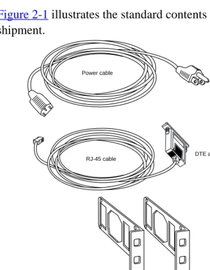
The standard contents of every Model 8000 RAC shipment include:
• A power cable
• An RJ-45 cable with DTE adapter
• Two rackmount brackets
• Twelve #6 flathead screws
• Four #10 rackmount screws and washers
[image:46.612.185.398.292.565.2]• Six rubber feet
Figure 2-1 illustrates the standard contents of your Model 8000 RAC shipment.
RA0020A
RJ-45 cable DTE adapter Power cable
Two rackmount brackets
Twelve #6 flathead screws Four #10 rackmount screws and washers
Preparing for Installation
To install the Model 8000 Remote Access Concentrator, you need:
• A console terminal
• A valid IP address
• An appropriate subnet mask
• A host with Model 8000 RAC software installed (if not booting from flash memory)
The RAC can obtain its operational image from any one of these sources:
• A UNIX host running erpcd
• A Windows NT host running erpcd
• Flash memory (self-boot)
• Another Model 8000 RAC configured as a boot host
• Any host supporting TFTP
The RAC must be connected to the network to receive its operational image, except when self booting. When self booting, the operational image is contained within the Flash memory of the RAC. A console terminal (connected to the console port on the rear panel) is the input device used to enter basic configuration parameter values for the RAC.
Booting from a UNIX Host
Booting from a Windows NT Host
If you plan to download the image from a Windows NT host to the RAC, you must first install the RAC operational software and image on the Windows NT host. Refer to Installing Remote Access Concentrator
Software for Windows and Windows NT for instructions and detailed
information.
To boot the RAC from a Windows NT host, you must have Remote Access Server Tools installed. Remote Access Server Tools uses the expedited remote procedure call daemon (erpcd) running on a Windows NT server.
Erpcd responds to all RAC boot and dump requests. Refer to Using
Remote Access Concentrator Server Tools for Windows NT®for
additional information.
Booting from Flash Memory
For more information on booting the RAC from Flash memory, see Self-Booting the Remote Access Concentrator on page -27.
Booting from Another Model 8000 Remote Access Concentrator
You can boot from another Model 8000 Remote Access Concentrator, if the Model 8000 Remote Access Concentrator you are trying to boot from is configured as a boot server. You can do this by using na or admin to set the annex server_capability parameter to image. Refer to Managing
Remote Access Concentrators Using Command Line Interfaces for
additional information.
Booting from a TFTP Host
Installing the Remote Access Concentrator in a Rack
If you wish, you can install the RAC in an equipment rack. To do this, you need the following equipment:
• Two mounting brackets shipped with the RAC
• Twelve #6 flathead screws shipped with the RAC
• Four #10 rackmount screws and washers shipped with the RAC
• Phillips screwdriver
You install the RAC in a rack by attaching mounting brackets to the sides of the device and then attaching the device to the rack.
Attaching the Mounting Brackets
To attach the mounting brackets to the RAC:
1. Remove the two mounting brackets and the 12 #6 flathead
screws from the package.
2. Line up the six holes in one mounting bracket with the six
holes on the RAC (Figure 2-2).
3. Insert and tighten the six screws to secure the bracket to the
4. Attach the other mounting bracket in the same manner.
Figure 2-2. Attaching the Mounting Brackets to the RAC
8000 Remote Access Concentrator
WAN 1 WAN 2
LAN Status Status Alar
ms Channel Activity % Utilization Test Red
Sync Yel LOS Blu 20 40 60 80 100 FULL
20 40 60 80 100 FULL Status Alar
ms Channel Activity % Utilization
Test Red Sync Yel Sync
Setup Power Stat Reset
Traf Attn LOS Blu
Attaching the Device to the Rack
To attach the device to the rack:
1. Position the unit horizontally, facing forward in the rack.
2. Align the holes in the mounting brackets with the holes in
the rack.
3. Insert the four #10 rackmount screws (with washers) and
[image:51.612.181.488.236.532.2]tighten the screws to attach the front of the RAC to the rack (seeFigure 2-3).
Figure 2-3. Attaching the Device to the Rack
Rail without threaded holes
Use cagenut Screws
(4 Places)
RA0006A
8000 Remote Access Concentrator
WAN 1
WAN 2 LAN Status
Status Alarms Channel Activity % Utilization Test Red
Sync Yel LOS Blu 20 40 60 80 100 FULL 20 40 60 80 100 FULL
Status Alarms Channel Activity% Utilization Test Red Sync Yel Sync
Setup Power Stat Test Traf
Connecting a LAN Using Ethernet
The RAC supplies AUI and 10BASE-T Ethernet ports on the rear panel for connecting a LAN (Figure 2-4).Appendix A describes the signal/pin allocations for the AUI and 10BASE-T Ethernet ports.
The 10BASE-T port is for connecting twisted pair cabling. The AUI port allows connection of either 10BASE5 (thick Ethernet) or 10BASE2 (thin Ethernet), if you supply the appropriate transceiver. The AUI port accommodates most standard tranceivers, also known as Media Access Units (MAUs).
Each connection type requires a different connection procedure
(described in the following sections). Connect only one type of Ethernet cabling at a time.
Make sure the RAC is turned off before connecting or disconnecting the Ethernet cabling.
Figure 2-4. Remote Access Concentrator Ethernet Connections
RA0007A
CONSOLE AUI 10BASE-T SYNC WAN 2 WAN 1
LINK
Thick/thin Ethernet (AUI)
Twisted pair Ethernet (10BASE-T)
Connecting AUI Cable
To connect an AUI cable to the RAC (Figure 2-5):
1. Make sure the transceiver cable is plugged into the Ethernet
network.
2. Push the slide mechanism on the RAC’s Ethernet connector
to the right and plug in the transceiver cable.
3. Push the slide mechanism to the left to secure the
connection.
Figure 2-5. Connecting an AUI Cable
CONSOLE 10BASE-T
SYNC AUI
WAN 2
100-240~3.2A 5060 Hz WAN 1 LINK
Connecting Twisted Pair Ethernet (10BASE-T) Cable
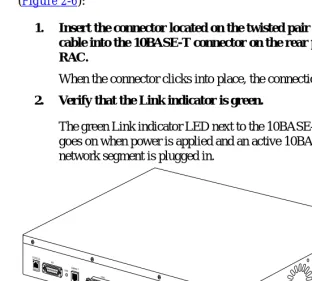
To connect twisted pair (10BASE-T) Ethernet cable to the RAC (Figure 2-6):
1. Insert the connector located on the twisted pair Ethernet
cable into the 10BASE-T connector on the rear panel of the RAC.
When the connector clicks into place, the connection is secure.
2. Verify that the Link indicator is green.
[image:54.612.164.476.163.444.2]The green Link indicator LED next to the 10BASE-T connector goes on when power is applied and an active 10BASE-T network segment is plugged in.
Figure 2-6. Connecting Twisted Pair Ethernet Cable
CONSOLE
SYNC LINK
RA0009A
10BASE-T AUI
WAN 2
Connecting a Console Terminal
You use a console terminal to access the ROM monitor and boot the RAC for the first time. To connect a console terminal to the console port located on the rear panel of the RAC:
1. Connect one end of the cable (provided in the accessory kit)
to the console terminal’s I/O connector, using a DB-25 DTE drop adapter (Figure 2-7).
Figure 2-7. Connecting the Cable to the DB-25 DTE Drop Adapter
2. Plug the 8-pin connector into the console port located on the
back panel of the RAC (Figure 2-8).
When the connector clicks into place, the connection is secure.
Appendix A describes the console port’s signal/pin allocation.
Figure 2-8. Connecting a Console Terminal
3. Turn on the console terminal and set the terminal to 9600
baud, 8 data bits, no parity, 1 stop bit, and no flow control.
The ROM monitor assumes that this terminal is CRT-based and displays the backspace (BS) character accordingly. See
Powering Up and Testing the Remote Access Concentrator on page 2-17for information about invoking the ROM monitor.
CONSOLE
SYNC LINK
RA0011A
10BASE-T AUI
WAN 2
Connecting WAN Interfaces
The WAN Interfaces connect the RAC to channelized T1, channelized E1, and ISDN PRI lines. To connect the lines to the WAN Interface ports:
1. Configure the WAN interface using any of these tools:
• The admin CLI command (refer to Managing Remote
Access Concentrators Using Command Line Interfaces
for details)
• Annex Manager (refer to Managing Remote Access
Concentrators Using Annex Manager for details)
• Quick2Config Annex (if you are using a PC; see the online help for Quick2Config Annex for details)
The switch type and other WAN parameters must be configured properly to be compatible with those provided by the telco. The telco may disable lines connected to an improperly configured device.
2. Plug the RJ-48C connectors located on the WAN interface
cable into the WAN interface ports located on the rear panel of the RAC (seeFigure 2-9).
Observe handling precautions for digital telecommunications cables.
When the connector clicks into place, the connection is secure. Appendix A describes WAN interface port signal/pin
Figure 2-9. Connecting the WAN Interfaces
The RAC uses an internal Channel Service Unit (CSU) for T1 applications. An internal CSU is not used in E1 applications.
CONSOLE
SYNC LINK
RA0010A
10BASE-T AUI
WAN 2
Initial Setup Using the ROM Monitor
After installing the RAC software on the file server host, collect the following information, which is required to determine the RAC’s boot parameters:
• The location (directory path) of the download files on the host (tftp only)
• Whether the RAC and host are on the same subnet or are separated by one or more routers
• Whether the host will use tftp or erpcd (requires a UNIX or Windows NT host) to download code to the RAC
You need this information to perform an initial boot when loading the software. Enter these parameters into the EEPROM using the ROM monitor commands, which are accessed through a console terminal. See
Chapter 3 for more information about these commands.
The RAC supports the Bootstrap Protocol (BootP) and the Reverse Address Resolution Protocol (RARP), which can be used to obtain some of the information listed. If you have a host running BootP or RARP, the server will boot without user intervention. For more information about using these protocols, seeAutoinitializing the IP Address Parameters on page 2-19.
The RAC supports Windows NT host tools. Remote Access Server Tools allows you to boot and configure the RAC on a Windows NT network. For more information, refer to Using
Remote Access Concentrator Parameters
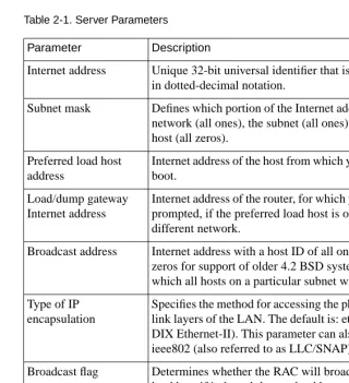
[image:60.612.160.480.206.556.2]You must set certain parameters from the ROM monitor before booting the RAC from a host (Table 2-1). After the RAC boots, you can change these parameters using the na utility. If you make any changes to these parameters, you must reboot the RAC for the changes to take effect.
Table 2-1. Server Parameters
If you plan to use Annex Manager or Quick2Config Annex to manage or configure the RAC, you must enable SNMP sets using the allow_snmp_sets ROM Monitor command. See
allow_snmp_sets on page 3-7 for details. Parameter Description
Internet address Unique 32-bit universal identifier that is specified in dotted-decimal notation.
Subnet mask Defines which portion of the Internet address is the network (all ones), the subnet (all ones), and the host (all zeros).
Preferred load host address
Internet address of the host from which you want to boot.
Load/dump gateway Internet address
Internet address of the router, for which you will be prompted, if the preferred load host is on a different network.
Broadcast address Internet address with a host ID of all ones (or all zeros for support of older 4.2 BSD systems) to which all hosts on a particular subnet will respond.
Type of IP encapsulation
Specifies the method for accessing the physical and link layers of the LAN. The default is: ethernet (for DIX Ethernet-II). This parameter can also be set to ieee802 (also referred to as LLC/SNAP).
Powering Up and Testing the Remote Access
Concentrator
This section describes how to power up and test the RAC, and enter monitor mode to configure the unit.
To power up and test the RAC:
1. If you have not already done so, connect a terminal to the
console port as described on page 2-11.
2. Plug the unit into an AC power outlet and turn on the power
switch. The Power LED lights.
3. Press the Reset button momentarily. The amber Setup LED
lights.
The unit now runs its ROM-resident power-up diagnostics. The LEDs light and then turn off, except for some status LEDs. The diagnostics take about a minute to complete.
If the diagnostics complete successfully, the RAC either enters Setup mode and waits for configuration data to be entered or boots its operational image from flash memory.
You can enter configuration information through the terminal connected to the console port. The ROM monitor prompt (monitor::) appears on the terminal.
If the ATTN LED is ON or flashing, one of the following failures has occurred (see Chapter 4 for more details):
• Hardware failure; contact technical support.
• Network or network interface failure; error message appears on the console.
If a network or network interface failure occurs, typingq
4. Verify the RAC hardware configuration.
At themonitor:: prompt, type config and pressReturn. The screen displays information similar to this:
5. Verify and record the RAC’s Ethernet address for future
reference.
At the monitor prompt, type addr -d and press Return. The screen displays information similar to this:
REVISION/CONFIGURATION INFORMATION
ROM Software Rev: 1122
Board ID: 64 Board Type: 8000
CPU Type: 486DX2 Ethernet Address: 00-80-2d-xx-xx-xx
Memory size: 8 Meg EEPROM size: 65504
Flash size: 4 Meg Flash ID:0089
Available Interfaces (* = selected): ThickNet *Twisted Pair
WAN 1: CAS E1 Revision: VERSION CAS MGR=2.1
WAN 2: CAS E1 Revision: VERSION CAS MGR=2.1
SLC 1
SLC SRAM Size: 128 K Modem Count: 31 Modem Rev: 0
SLC 2
SLC SRAM Size: 128 K Modem Count: 31 Modem Rev: 0
monitor:: addr -d
Ethernet address (hex): 00-80-2d-XX-XX-XX
Internet address: <uninitialized>
Subnet mask: 255.255.0.0
Broadcast address: 0.0.0.0
Preferred Load Host address: <any host> Preferred Dump Host address: 0.0.0.0
Load/Dump Gateway address: 0.0.0.0
Type of IP packet encapsulation: <ethernet>
Booting the Remote Access Concentrator
You can boot the RAC by downloading the image from a host system or another Model 8000 Remote Access Concentrator, or by using the image contained in flash memory (self-boot). However, before you actually boot the RAC, you must first initialize the IP address parameters manually or by using the autoinitialize feature. The following sections describes the two methods of initializing the IP address parameters, and the various boot methods.
Autoinitializing the IP Address Parameters
The RAC is distributed without an IP address or preferred load host defined in ROM. When you boot RAC, it attempts to initialize itself (autoinitialize) using BootP (Bootstrap Protocol) and RARP (Reverse Address Resolution Protocol).
This method of initializing the IP address parameters is generally done when booting from a host system (not when self-booting).
The RAC supports the BootP and RARP protocols. These protocols obtain boot information from a UNIX host without requiring any manual setup on the RAC.
• BootP allows a diskless client to determine its IP address, the IP address of the server, and the name of the file to be loaded into memory.
• RARP maps a hardware address into an IP address.
If all requests fail, the RAC returns to the ROM monitor (if in Setup mode) or continues the autoinitializing procedure indefinitely (if in normal mode).
BootP
For a successful BootP retrieval, you must be running a bootpd daemon on a host on the same subnet as the RAC (or have a router on the same subnet that supports BootP forwarding) and must have the appropriate information in the bootptab file. The BootP implementation for the RAC adheres to RFC 951, RFC 1048, and RFC 1084. A sample bootptab file entry used to initialize the RAC named terminator looks like this:
In this example:
• sm isthe subnet mask.
• gwis the load/dump gateway address.
• vm is the Vendor Magic Cookie.
• htis the host type (1=Ethernet).
• hais theRAC’s hardware address (Ethernet Address).
• ip is theRAC’s IP address. remoteannexdefault:\
:sm=255.255.255.0:gw=132.245.22.66:\ :hn:vm=auto:to=-18000:
terminator:\
When the RAC receives a BootP response with the sm, gw, and ip set, it sets the respective parameters: subnet_mask, load_dump_gateway, and
inet_addr. The Vendor Magic Cookie must be set to auto. This indicates
that bootpd should respond to the client (Model 8000 Remote Access Concentrator, in this case) with whatever format the client requests. The Model 8000 Remote Access Concentrator (client) always makes requests with the Vendor Magic Cookie set to 99.130.83.99.
The bootpd daemon adds the address of the host on which it is running as the Server Address in the bootp response message. The ROM uses the
Server Address as the preferred load host and stores it in the
pref_load_addr parameter.
The host running bootpd (the preferred load host) must also be running erpcd or tftpd.
RARP
If the RAC does not receive a successful BootP response, it uses RARP to get the boot information. For a successful RARP retrieval, TCP/IP must be running on a host that is on the same subnet as the RAC, and the host’s ARP table must be initialized with the RAC’s IP and Ethernet addresses (see the arp man page for arp –s).
The host providing the RAC with boot information must be running on the same subnet as the RAC because the RAC broadcasts BootP and RARP queries using the “this network” IP address, 255.255.255.255.
If BootP and RARP fail, the RAC transmits an IPX Advertisement Request for Service.
If all requests fail, the RAC returns to the ROM monitor (if in Setup mode) or continues the autoinitialization procedure indefinitely (if in Normal mode).
After the RAC has successfully initialized, it is ready to be booted. See
Booting Using BFS on page -23,Booting Using TFTP on page -24, or
Self-Booting the Remote Access Concentrator on page -27 for detailed information about booting the RAC.
Manually Initializing the IP Address Parameters
To configure the RAC for your specific needs, the IP address parameters can be manually initialized by performing the following steps:
1. Enter the addr command at the monitor prompt.
The following prompt is displayed:
Enter Internet address::
2. Enter the IP address for the RAC.
You are prompted to enter the server subnet mask, preferred load host, preferred dump host, IP packet encapsulation, and load broadcast flag. The defaults are listed after each prompt.
3. Modify the parameter next to each prompt, or press Return
to retain the current setting.
After the RAC has successfully initialized, it is ready to be booted. See
Booting Using BFS on page -23,Booting Using TFTP on page -24, or
Booting Using BFS
To boot the RAC using the block file server (BFS):
1. Initialize the IP address parameters using either the
autoinitialize or manual initialize method.
The autoinitialization method is described inAutoinitializing the IP Address Parameters on page 2-19. The manual
initialization method is described inManually Initializing the IP Address Parameters on page 2-22.
2. Enter the boot command.
If you do not enter a file name with the command, you are prompted for one (the default file name is displayed at the prompt: oper.64.enet). Press Return to boot using the default file name.
The following example shows a typical screen display for a BFS boot using erpcd on UNIX or Windows NT:
Enter boot file name[oper.64.enet]::
Requesting boot file ”oper.64.enet”.
Unanswered requests shown as ’?’,transmission errors as ’*’.
Requesting boot from 192.9.200.88 via Ethernet... Booting BFS file using open delay of 8
Booting BFS file from 192.9.200.88
The download takes from 30 to 60 seconds for a Model 8000 Remote Access Concentrator booting over the local network. After the download is complete, the Power, Unit, and Net LEDs remain on. If these LEDs do not remain on (indicating a problem), seeChapter 4.
Once the RAC is booted, Monitor mode is no longer operational. The RAC is up and running, and the following message is displayed:
Console monitor ready; Press CR to start
Booting Using TFTP
To boot using TFTP, your TFTP daemon (tftpd) must be started in /etc/inetd.conf (or another appropriate directory on your system) with a configuration line similar to this:
tftp dgram udp wait root /usr/etc/in.tftpd in.tftpd -s/tftpboot
If you omit the-s /tftpboot, a chroot will not be done, and your system will be not be secure.
To set up directories and files and use TFTP to boot the RAC:
1. Initialize the IP address parameters using either the
autoinitialize or manual initialize method.
The auto-initialization method is described inAutoinitializing the IP Address Parameters on page 2-19. The manual
2. Enter the image command at the monitor prompt.
When prompted, enter the following information:
• Boot image name
• Boot directory
• Dump file name
The default image file name is:oper.64.enet
The following example shows how the image command is used to set up a RAC boot from the /tftpboot/annex/ directory. When you enter the load directory name, make sure you end the path name with a slash character.
Image name: <invalid or uninitialized> Default: “oper.64.enet”
Enter Image name::oper.64.enet Image name: “oper.64.enet” TFTP load directory:
Enter TFTP load directory::/annex
TFTP Dump path/filename: <uninitialized> Default: “dump.134.117.6.34”
Enter TFTP Dump path/filename::/annex/mydumpfile Using current TFTP Dump path/filename.
monitor::
3. Execute the following commands to prepare the tftp dump
file.
touch /tftpboot/annex/mydumpfile
4. Enter the boot command.
The boot command displays information similar to this:
Enter boot file name[oper.64.enet]::
Requesting boot file ”oper.64.enet”.
Unanswered requests shown as ’?’,transmission errors as ’*’.
Requesting boot from 192.9.200.88 via Ethernet... Booting BFS file using open delay of 8?
Booting TFTP file using open delay of 8 Booting TFTP file from 192.9.200.88
Header received OK. Received data blocks shown as ’.’. . . . . . . . . . . . . . . . . . . . . . . . . . . . . . . . . . . . EOF
After the RAC boots, Monitor mode is no longer operational. The RAC is up and running, and the following message is displayed:
Self-Booting the Remote Access Concentrator
The RAC comes equipped with Flash memory that contains an operational image you can use to self-boot the unit. To self-boot your RAC:
1. Initialize the IP address parameters using the manual
initialize method.
The manual initialization method is described inManually Initializing the IP Address Parameters on page 2-22.
2. Enter the sequence command at the monitor prompt.
The following prompt is displayed:
Enter interface sequence [net]::
3. Enter self, net as the sequence.
The monitor prompt is displayed.
4. Enter the boot command at the monitor prompt.
The display looks similar to this:
monitor:: boot
Requesting default boot file “OPER_64_ENET.SYS” for MOP/VMS\ loads and “oper.64.enet” for all other protocols. Unanswered requests shown as ‘?’, transmission errors as ‘*’.
Booting file: “OPER_64_ENET.SYS” from SELF
Loading image from SELF ...
... Load Completed
Invoking the Console Monitor
After the image boots, you can invoke the Console monitor by pressing Return on the console terminal. The following prompt appears:
Console monitor:
At the Console monitor prompt, entering help or ? displays the available options:
• afd (displays the status of the Automatic Firmware
Download process - used only for the WAN interfaces)
• cli (starts the Command Line Interpreter on the current port)
• dump (from the RAC to the host and reboots)
• help or ? (displays the available options)
• info (displays configuration information for the unit)
• leds (displays the current front panel LED status)
• quit (quits and returns to quiet console)
• reboot filename (reboots the unit)
• rom (returns the RAC to the ROM monitor)
T
his chapter describes the ROM Monitor commands that are available in Monitor mode. Access these commands through a terminal connected to the console port.The ROM Monitor commands allow you to set a subset of the
configuration (EEPROM) parameters. Some of these parameters, such as the unit’s IP address, are required for booting the Model 8000 Remote Access Concentrator; some parameters, such as the broadcast address, are required if the network configuration differs from the supplied defaults.Table 3-1 lists the ROM Monitor commands.
Other parameters, although not required, are recommended for the RAC’s initial boot. Setting these parameters, rather than using the assigned defaults, minimizes errors during the initial boot. For example, setting the parameter that defines the preferred load host enables the RAC to load by requesting assistance from a specific host, rather than by broadcasting that request to all hosts on the subnet.
After the RAC boots, you can define the same parameters you defined using the ROM Monitor, by using the host-based na utility, the local CLI
admin command, or SNMP. Managing Remote Access Concentrators
Using Command Line Interfaces describes the na utility in detail. See
Chapter 2for information about power-up and boot procedures.
Default or current values for parameters are displayed in brackets. For example:
Enter broadcast address [132.245.6.255]:
At the prompt, enter a different value, or press Return to leave the displayed value unchanged.
You can use unique abbreviations for all ROM Monitor commands except
erase. For example, enter boot as bo, and enter net as n. If you enter an
abbreviation that is not unique, an error message is displayed on the console terminal.
Command Descriptions
Table 3-1 lists the ROM Monitor commands; the following sections describe them.
Table 3-1. ROM Monitor Commands
Command Description Use
addr [-d] Displays and sets
EEPROM values relevant to IP network addressing, including the unit’s IP address.
Changing IP configuration parameters.
allow_snmp_sets [-d] Enables/disables the RAC’s ability to accept SNMP sets.
Allowing or not allowing the RAC to be configured using SNMP sets.
boot [-v] [<file>] Manually boots and loads the unit’s operating code.
Changing the address of the boot image.
boot [-l] [<file>] Erases the existing flash memory and copies a new image to flash memory.
Table 3-1. ROM Monitor Commands (continued)
Command Description Use
config Displays the current
hardware configuration and revision levels.
Identifying your hardware, memory, and ROM versions.
erase Erases nonvolatile
memory.
Clearing out old parameters.
help Displays the list of ROM Monitor commands.
Referencing the ROM monitor commands.
image [-d | <file>] Displays and/or sets the load image and tftp load dump names.
Loading an image that differs from the default.
lat_key [-d] Sets the LAT key. Connecting to a VMS
host.
net Executes an Ethernet transceiver loopback test.
Checking your Ethernet connection.
ping Sends ICMP
ECHO_REQUEST datagram to a host or gateway.
Checking to see whether a host or gateway can be reached.
ports [-d] Shows the current status
of a WAN interface port.
Testing a WAN interface port or modem hardware.
sequence [-d | <list>] Displays and edits the load/dump interface list.
Checking or changing the load/ dump interface list.
stats Displays current network
statistics gathered by the ROM.
addr
The addr command sets and displays several RAC operating parameters (EEPROM values) relevant to IP network addressing:
• Internet address
• Subnet mask
• Broadcast address
• Preferred load host address
• Preferred dump host address
• Load/dump gateway address
• Type of IP packet encapsulation
• Lo