Gesture Controlled Robotic Arm
Nayan. S. Satghare
Dept. of Electronics and telecommunication Engineering, Sinhgad Institute of Technology Lonavala, Pune, Maharashtra, India
Abstract: In many applications of controlling robotic gadget it becomes quite hard and complicated when there comes the part of controlling it with remote or many different switches. Mostly in military application, industrial robotics, construction vehicle in civil engineering side, medical application for surgery. Sometimes the operator may get confused in the switches and buttons itself, so as a new concept is introduced to control the machine with the movement of hand which will simultaneously control the movement of robot. In my project I am using this concept to control the robot through the movements of our hands and also the movement of our ‘fingers’. I have combined the two robot types that is a robot car and a robotic arm to make one single multipurpose robot. My project is a concept introducing robot and its uses. By making more advancement in it i.e. by changing the end effector it can be used in military appliances like bomb diffusing robot. The sensors can also be used to make wheel chair for patients who can’t walk.
Keywords: ATMega328, Flex Sensors, Accelerometer ADXL335, HC-05 Bluetooth Sensor, Android App.
I. INTRODUCTION
Gesture Controlled Robot is a kind of robot which can be controlled by the movements of your hand and not by the old buttons. You just need to wear a glove in your hand which includes sensors like an accelerometer for the movement of the robo car and flex sensors on the fingers to control the robotic arm. The accelerometer will control the robot for its movement in forward, reverse, left and right direction where we want to move the robot. While this was how robo car operates the controlling of the robotic arm is done using flex sensors mounted on our fingers, so as we bend our fingers the movement of robotic arm in left, right, up, down, holding object or releasing the object will take place. We have seen many projects on robo car or robotic arm in which they are displayed separately so I just combined them making a multipurpose robot. This robot can also be made more useful by making further improvements by placing a camera over it to use it in military application or we can also use the concept of gesture control to make appliances for the partially disabled people. Robots are mostly made to make human life easy and it is really good to see that it is really helping humans in their work by making it easier and to do things that humans can’t or are unable to do. Robotics is a field that is going on improving day by day.
II. OVERALL DECRIPTION
The Robot comprises three sections viz. the Input section, the Control Section and the Output section. The control section comprises of the microcontroller which takes decisions on the input given to it through input section. The processed signal is the given to the output section. The microcontroller works on 5V dc. The input section comprises of the Flex sensors and the Accelerometer which are used to give input to the microcontroller. The flex sensors and accelerometer both works on 5V dc which is received from microcontroller. The output section comprises of two types of motors used to drive the robo car and the robotic arm. The dc motors are attached to the microcontroller through a driver IC L293D. This IC requires 12V and 5V dc supply which is acquired from the battery and microcontroller. The servo motors are attached to the microcontroller using the current amplification circuit working on 5V dc.
III. SPECIFICATIONS
A. Atmega328
Fig.1 ATMega328
B. Flex Sensors
For the working of robotic arm, the flex sensors are used which are placed on the glove. Flex sensors are sensors that change in resistance depending on the amount of bend on the sensors. They convert the change in bend to electrical resistance-the more the bend, the resistance value. They consist of an LED, LDR and 2 Resistors. Fig 3 is of the circuit used to build the flex sensors.
Fig.3 Circuit used to build Flex Sensors
Fig.4 Flex Sensor Resistance Diagram
C. Accelerometer ADXL
An Accelerometer is an electromechanical device that measures acceleration forces. These forces may be static, like constant force of gravity pulling at your feet, Or they could be dynamic caused by moving or vibrating the accelerometer It is a kind of sensor which record acceleration and gives an analogue data while moving in X, Y, Z direction or may be X, Y direction only depending on the type or the sensor.
D. Bluetooth Module HC05
HC-05 module is an easy to use Bluetooth SPP (Serial Port Protocol) module, designed for transparent wireless serial connection setup. It has the footprint as small as 12.7mmx27mm. It is connected to android mobile using its inbuilt Bluetooth and receives signal from the android app and delivers characters to microcontroller accordingly. It has features like-
o Up to +4dBm RF transmit power
o Low Power 1.8V Operation,1.8 to 3.6V /O
o Default Baud rate: 38400, Data bits:8, Stop bit:1, Parity: No parity, Data control has supported baud rate:9600,19200,3 8400,57600, 115200,230400,460800.
o Auto-connect to the last device on power as default.
Fig.6 Bluetooth Module HC-05
E. DC Motors
DC motors were the first type widely used, since they could be powered from existing direct current lighting power distribution systems. A DC motor's speed can be controlled over a wide range, using either a variable supply voltage or by changing the strength of current in its field windings. Small DC motors are used in tools, toys, and appliances. The universal motor can operate on direct current but is a lightweight motor used for portable power tools and appliances. Larger DC motors are used in propulsion of electric vehicles, elevator and hoists, or in drives for steel rolling mills. The advent of power electronics has made replacement of DC motors with AC motors possible in many applications.
Fig.7 DC Motor
F. Driver IC L293D
L293D is a Motor driver integrated circuit which is used to drive DC motors rotating in either direction. It is a 16-pin IC which can control a set of two DC motors Simultaneously. The L293D uses 5V for its own power and external power source is needed to drive the motors, which can be up to 36V and draw up to 600mA. The L293D works on the concept of typical H-bridge, a circuit which allows the high voltage to be flown in either direction. In a single L293D IC there two H-bridge circuits which can rotate two DC motors independently. Due to its size and voltage requirement, it is frequently used in robotics applications for controlling DC motors, including in Arduino projects.
G. Servomotor
This servo motor finds many applications in areas which require a 180 motion of light weight objects. Highly used in many robotic projects that require Pan-Tilt mechanisms for Cameras, Ultrasonic Sensors etc. This motor can also be used to make light weight and small- sized bipeds, humanoids, spiders (6- or 8- legged), robot hand, robot arm and other similar applications. This motor has 3 pins- middle wire (red) connects to Vcc, brown wire connects to GND, and yellow wire is signal which is to be connected to the digital pin of the Arduino board.
Fig.9 DC Servo Motor
H. Current Amplification Circuit
The Current Amplification circuit as shown above is used to drive the servo motors as the Output current from microcontroller is not sufficient to drive the 3 micro servo motors properly. The components used in the circuit are LM2576, 1000uF and 100uF capacitors, 100uH inductor and a Zener diode to get the output of 3A current.
Fig.10 Current Amplification Circuit
I. 12V Rechargeable Battery
As a supply a 12V rechargeable sealed lead-acid battery 1s used that supplies power to all the components. It gives 12V and 1.2Ah output. It requires maximum charging current of 0.36A. We used 12Vas we had to drive the motors and for supply to other components we down convert it using the LM2576 which is a voltage regulator to limit the output to 5V.
IV. SYSTEM DESIGN & METHODOLOGY
A. Block Diagram
B. Methodology
The Gesture controlled Robot is a robot that is controlled through the movements i.e. gestures of the hand. The person needs to wear a glove which contains sensors that are used to track the gestures of the hand and operate or control the robot. My Project consists robotic arm and robo car combined together to make a multipurpose robot.
[image:5.612.209.406.76.250.2]Here in my project I am using the Accelerometer ADXL 335 to control the robocar. The accelerometer senses the movements of our hand as shown in the figure below. According to the program fed to the microcontroller ATMega 328 these movements are given to driver IC L293D which will actuate the DC motors and move the robo car.
Fig. 12 Movements of hand
The movement of our hand as shown in Fig.12 will move the robo car in Left, Right, Forward, and Backward directions respectively.
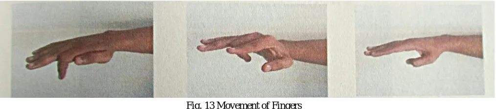
[image:5.612.57.564.533.645.2]The flex sensors are used to control the movements of the robotic arm via micro servo motors. The sensors are placed on the fingers so that as we bend our fingers they will cause a bend to sensors resulting in their operation due to change in resistance. The Fig.13 shows the possible gestures oh hand that I have used in my project.
Fig. 13 Movement of Fingers
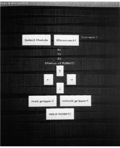
Fig. 14 Developed Mobile Application
This is the screen of the app that will be used to control the robot using Bluetooth module HC-05. The select module button will be used to connect the Android device to the Bluetooth module and Disconnect button to disconnect it. The X, Y, Z below the connection buttons will show the values of the Accelerometer that is inbuilt in the Android Device. By tilting the device in Forward, Backward, Left and Right direction the robot will move in those respective direction. The arrow keys are used to control the robotic arm in Up, Down, Left, and Right directions. For the operation of the End Effector i.e. Gripper two buttons are used named as Hold Gripper and Un hold Gripper. There is also a button named Hold Robot to stop the movements of the Robo car and only allow the movement of the robotic arm. And when we again long press this button the Robo Car is now permitted to make movements. These can be used where the precision is required.
VI. CONCLUSION
The project has been successfully designed and tested. It has been developed by integrating features of all hardware components used. Presence of every module has been reasoned out and placed carefully thus contributing to the best working unit. Secondly, using the highly advanced IC’s and with the help of growing technology the project has been successfully implemented. Finally I conclude that "GESTURE CONTROLLED ROBOT” is a multipurpose project which can be very useful in today 's generation.
VII. ACKNOWLEDGEMENT
It is my pleasure to present my research paper titled “GESTURE CONTROLLED ROBOTIC ARM”. The success and final outcome of this project required a lot of guidance and assistance from many people and I am extremely fortunate to have got this all along the completion of my project work. Whatever I have done is only due to such guidance and assistance and we would not forget to thank them. We are highly indebted to Assistant Professor of my college for giving me an opportunity to do the project and providing me all support and guidance, which made me to complete the project on time. I am thankful to and fortunate enough to get constant encouragement, support and guidance from all Teaching staffs of Department of Electronics and Telecommunication which helped me in successfully completing my project work. Also, I would like to extend my sincere regards to all the non-teaching staff of department of Electronics and Telecommunication for their timely support.
REFERENCES
[1] Pedro Neto, J. Norberto Pires, A. Paulo Moreira, "Accelerometer-Based Control of an “Industrial Robotic Arm" Available at:
http://arxiv.org/ftp/arxiv/papers/1309/1309.2090.pdf
[2] Dr. R. V. Dharaskar, S. A. Chhabria, Sandeep Ganorkar, "Robotic Arm Control Using Gesture and Voice", In International Journal of Computer, Information Technology & Bioinformatics (IJCITB), Vol. 1, Issue 1, pp. 41-46 Available at: http://www.ijcitb.com/issues/paper_9.pdf
[3] S. Waldherr, R. Romero and S. Thrun, 2000, "A gesture base interface for human-robot interaction", In Autonomous Robots in Springer, vol. 9, Issue 2, pp. 151-173 Available at: http://www.cs.cmu.edu/-thrun/papers/waldherr.gestures-joumal.pdf