© 2019, IRJET | Impact Factor value: 7.211 | ISO 9001:2008 Certified Journal | Page 4365
LATERAL PERFORMANCE BEHAVIOUR OF HYBRID COLD-FORMED
STEEL WALL SYSTEMS OPTIMISED WITH SUPA SECTIONS
Ananthu Krishnan N
1, Syno Abraham
21
P.G.Student, Department of Civil Engineering, Cochin Institute of Science & Technology, Muvattupuzha,
Ernakulam, India
2
Assistant Professor, Department of Civil Engineering, Cochin Institute of Science & Technology, Muvattupuzha,
Ernakulam, India
---***---Abstract –
The paper focused on analytical study for thelateral and Seismic behavior of hybrid steel wall systems. Cold formed steel channel sections are generally used as channel sections and are generally used as flexural members in light weight steel construction. Improved channel section profiles as Supa Cee section with longitudinal web stiffeners and curved lips are also used instead of conventional lipped channel sections. Web crippling capacities of these innovative sections can different from those of conventional lipped channel sections. Here firstly, a bending test is conducted in Supa Cee model and find out its load carrying capacities. We select more section like Zeed, Sigma section and find out its Web crippling capacities. Select the best section from above and it is used in Hybrid wall panel having a unique size 3m x 3m which adopt fully cold-formed steel or fully hot- formed steel or mix of both. Due to these different configurations of cold and hot formed steel, the structural performance of the structure is found out using pushover analysis and seismic analysis.
Key Words: Supa cee Sections, Supa Zeed Sections, Supa Sigma Sections, Hybrid Walls, Finite Element Analysis, ANSYS 16.1
1. INTRODUCTION
Cold-formed steel (CFS) section is the term used for products which are made by rolling or pressing thin gauges of steel sheets into goods. CFS construction materials differ in many respects than other steel construction materials like hot rolled steel. The manufacturing of CFS products occurs at the room temperature with the use of rolling/pressing. The buckling property is used to analyze the strength of elements. In comparison to the hot rolled section with the cold rolled sections, CFS having more moment of inertia and section modulus in x-direction and y-direction, therefore the load carrying capacity and moment resisting capacity are higher than hot rolled section. Cold-formed steel elements are having two types, stiffened or unstiffened. The stiffened elements obtained by an element supported by webs along both longitudinal edges. While the unstiffened element is obtained when the element supported along
any one longitudinal edge only and the other edge can have the displacement.
The aim of this paper is to analyses the structural performance of Hybrid cold formed steel wall panel under lateral loads loading by means of their load carrying capacity. The load-deflection relation of different shaped steel sections is firstly evaluating from the software. The Section having better performance is used as Hybrid wall panel structure. Bending Test and Axial Load are key for evaluate better performance of Supa Sections. Lateral load are applied at Hybrid wall panel having supa sections at the inner walls (Normal CFS) and Box type Hot rolled steel sections are used in outer sections. .
This study is to conduct an evaluation on strength behavior, ductility behavior, stress distribution and load-deflection by FEA with Hybrid wall having different shaped supa steel sections. The lateral loading, axial loading are applied on all the cases. By analyzing the load-deflection curve, find out the performance of the Hybrid panel under various shaped steel sections.
1.1 Objectives
The aim of the project is analyze the best configuration of the hybrid wall having high performance in load carrying capacity and high ductile performance. An extensive parametric study was conducted on this finite element models to investigate the strength behavior, ductility behavior, load deflection and stress distribution of hybrid wall having steel sections like supa cee, supa zeed , supa sigma using either beam or column under lateral load conditions.
2. MODELLING AND ANALYSIS
© 2019, IRJET | Impact Factor value: 7.211 | ISO 9001:2008 Certified Journal | Page 4366 materials consist of structural steel its engineering data are
assigned. Table 1 shows the material property of connection elements.
[image:2.595.53.279.147.268.2]Fig -A: SupaCee Steel Section
Table -1: Material property of connection elements
Material Modulus of
elasticity (GPa)
Poisson’s
ratio Yielding stress (MPa)
Ultimate stress (MPa)
SUPACEE COLD FORM
SECTION
200 0.3 342 540.62
2.1 Boundary Condition, Contact Interactions and
Loading
The SupaCee (with Crip) steel section is considered as specimen. In software it is place as like a beam and bending load is applied at the end ie, End Two Flange Loading.
2.2 Selected Parameters
The dimensions of the steel sections are considered equal with Crip or stiffeners . The first parametric study was change in shape of steel sections. Two more shape are selected they are Supa Zeed, Sigma etc.
The secondly changed parameter was the steel section without Crip i.e. C, Z Sigma Sections. After that the best section is taken from the above analysis.
Moreover, consider the parameter of steel sections considered as column. Axial load is applied for column parameter.
Third parameter was application of each section as inner beam and column in Hybrid wall panel. In Hybrid wall panel the outer wall is taken as Hot rolled steel and inner beam and column are taken as cold formed steel sections. For this analysis the best position of joint is taken from the above analysis.
Finally, lateral loading is selected for the performance evaluation like strength behavior, ductility behavior and stress distribution of different wall panel models. The analysis was done in ANSYS software.
Fig -1: Boundary conditions and lateral loading
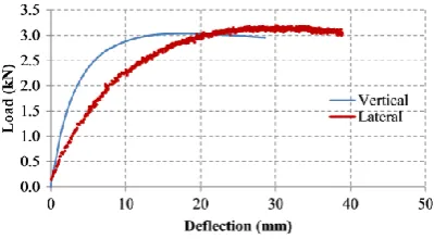
Chart -1: Load deflection curve
In the finite element software, loading was applied statically which a displacement control loading is to the top of the column up to the final loading step. Chart 1 shows the curve of the load of SupaCee section vs. the horizontal displacement in mm. Then analyses the model in ANSYS Workbench 16.1.
3. RESULTS AND DISCUSSION
3.1 The Performance of Change in Shape of Steel
Section
In this study, there are six models. In each model have same overall weight. The dimensions of the steel sections is considered with Crip and without Crip. The models are different just in the shape of sections.
[image:2.595.328.528.281.391.2] [image:2.595.37.293.315.379.2]© 2019, IRJET | Impact Factor value: 7.211 | ISO 9001:2008 Certified Journal | Page 4367 SUPA SIGMA – BENDING
LOAD C SECTION- BENDING LOAD
Z SECTION- BENDING
[image:3.595.42.282.88.284.2]LOAD SIGMA SECTION- BENDING LOAD
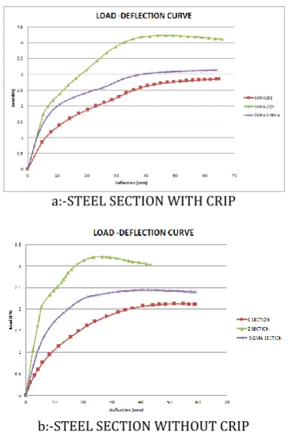
Fig -2: Deflection of Steel Section with and without Crip
a:-STEEL SECTION WITH CRIP
b:-STEEL SECTION WITHOUT CRIP Chart -2: Load deflection curve
Chart. 2(a) shows the load-deflection graph of the SupaCee, SupaZeed and Supasigma sections. According to this graph the SupaZeed have the maximum bending or crippling load carrying than the Supa Cee and Supa Sigma. The SupaZeed can carry 31% of additional bending load than the Z section without Crip.
Chart. 2(b) shows the load-deflection graph of C, Z and Sigma Sections. According to this graph Z section have a larger bending load carrying capacity than the C and Sigma
sections. The Z section can carry 31% of additional axial load than the Sigma Sections.
Fig 2:- shows the deflection parameter of each steel sections. The bending load is applied at the End Two Flanges of the sections. In both with or without Crip case the larger load carrying capacity is Supa Zeed and Z Sections respectively than other sections. But in the case of deflection, SupaCee and C sections are more deformed than other sections.
3.2 The Performance of application of Axial Load
in sections
In this study, there are three models and each model have same dimensions according to their shapes. The models are difference in the shape, i.e, SupaCee, SupaZeed, and SupaSigma. The overall weight of the sections dimensions are kept constant.
SUPA CEE COLUMN
SUPA ZEED COLUMN
[image:3.595.60.264.315.625.2]© 2019, IRJET | Impact Factor value: 7.211 | ISO 9001:2008 Certified Journal | Page 4368 Fig -2: Deflection of Steel Section in axial load
Chart -3(a): Load deflection curve
Chart -3(b) : Load deflection curve
Chart. 3(a) shows the load- deflection curve Supa Sections under axial loading. According to this curve the SupaSigma increase (45%) in load carrying capacity than the SupaCee, section. From the graph the deflection of the SupaSigma section is increases with the load applied, after a maximum load of 214.93Kn is reached it decreases with deflection
Chart. 3(b) shows the load comparison chart of the steel sections under axial loading,
3.3 The Performance of Change in position of
steel sections in Hybrid wall
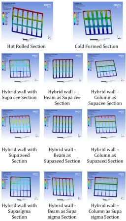
In this study, there are eleven different models are taken. The dimensions of hybrid wall in unique in size. In each Hybrid wall panel, the outer wall is taken as Hot rolled section and Inner walls are taken as Normal Cold Formed steel sections. In fig 4:- shows that the various pattern of steel sections in hybrid wall. The arrangements of Supa Sections are either beam or column or both. For example: Hybrid wall with SupaCee section shows that Outer wall is box type Hot rolled sections and inner walls are Normal Cold form Supacee shaped steel sections. From the
analyses of the wall panel by applying lateral load, the best model having high load carrying capacity is selected.
Hot Rolled Section Cold Formed Section
Hybrid wall with
Supa cee Section Beam as Supa cee Hybrid wall – Section
Hybrid wall – Column as Supacee Section
Hybrid wall with Supa zeed
Section
Hybrid wall -Beam as Supazeed Section
Hybrid wall – Column as Supazeed Section
Hybrid wall with Supasigma
Section
Hybrid wall -Beam as Supa sigma Section
Hybrid wall – Column as Supa
sigma Section
Fig -4: Deflection of various steel sections in Hybrid wall
(a) Supa cee Steel Section 0
100 200 300
SUPA CEE
SUPA ZED
SUPA SIGM A Series1 148.16 160.54 214.93
Load
(
kN
)
[image:4.595.307.564.131.582.2]© 2019, IRJET | Impact Factor value: 7.211 | ISO 9001:2008 Certified Journal | Page 4369 (b) Supa zeed Steel Section
(c) Supa sigma Steel Section
Chart -4: Load deflection curve
Chart. 4(a) shows the load-deflection of SupaCee steel section under lateral loading. Hybrid wall with SupaCee sections (Cold formed steel sections) having 76% larger loading carrying capacity than Hybrid wall panel having Hot rolled structures.
Chart. 4(b) shows the load-deflection of SupaZeed steel section under lateral loading. Hybrid wall with SupaZeed sections having 50.5% larger loading carrying capacity than Hybrid wall panel having Hot rolled structures.
Chart. 4(b) shows the load-deflection of SupaSigma steel section under lateral loading. Hybrid wall with Supasigma sections having 87% larger loading carrying capacity than Hybrid wall panel having Hot rolled structures.
As compare the Hybrid wall panel structure having fully Normal Cold formed steel sections having a higher (24%) of loading carrying capacity than Hot rolled steel sections. .
4. COMPARISON OF RESULTS
All models were analyzed under different loading conditions such as lateral loading, bending test and axial load. In each model have same dimensions according to their shapes. The change in shape of steel sections used in
the hybrid wall panel shows the different load carrying capacities of wall.
4.1 The Effect of bending test in steel section
Chart-5 presents the comparison in bending load on all six models. According to these figure, the SupaZeed have the larger load bearing capacity than all other models. In conventional type the Z section having higher loading capacity than C and Sigma sections.
Chart -5: Comparison of Load – under bending test
Chart -6: Comparison of Deflection – under bending test
Chart-6 shows the comparison of deflection under bending loading. According to this figure the SupaCee have a larger deflection than all other sections. The SupaCee has an 18% more deflection than the conventional C Section. The SupaCee sections has 39% of more deflection than the SupaZeed sections.
4.2 The Effect of Axial load in steel section
© 2019, IRJET | Impact Factor value: 7.211 | ISO 9001:2008 Certified Journal | Page 4370 Chart -7: Comparison of Load – under Axial test
Chart -8: Comparison of Deflection – under Axial test
Chart-8 shows the comparison of deflection under axial load on all three models. According to these figure, the SupaZeed have a 27 % higher deflection than SupaCee.
4.2 The Effect of Hybrid Wall panel using
different steel section
Chart-9 presents the comparison of effect of different steel sections in Hybrid wall panels under lateral load. According to these figure, Hybrid wall panel having fully Supasigma sections have larger load carrying capacity. The Supasigma Steel section having a 6 % larger load carrying capacity than SupaCee Sections.
Chart -9: Comparison of Load – wall having various section panel
Chart -10: Comparison of deflection – wall having various section panel
Chart-10 shows the comparison of deflection under lateral loading. According to this figure SupaSigma having higher deflection than other steel sections. The Supasigma Steel section having a 6.42 % larger deflection than SupaCee Sections.
5. CONCLUSIONS
The following conclusions may be drawn from the Finite Element Analysis (FEA) performed on all models the following conclusions were obtained by using finite element analysis software ANSYS Workbench 16.1.
• On the performance evaluation of supa and conventional type steel sections, the supa sections having higher loading capacity than conventional type.
•In supa sections, SupaZeed having higher load carrying capacity and lower deflection than other sections.
• In conventional section, Z sections having higher load carrying capacity and lower deflection than other sections. • Under the Axial Load, the SupaSigma Sections having 45% load carrying capacity than other supa cee sections. • The Normal Cold Formed Steel Sections having higher strength than Hot rolled strength under Lateral load. • The load carrying capacity and deflection is higher in Hybrid wall having SupaSigma steel sections than other sections.
REFERENCES
1. American Iron and Steel Institute (AISI). Specifications for the cold-formed steel structural members, cold-formed steel design manual. AISI S100, Washington DC, USA; 2012.
2. Standards Australia/Standards New Zealand. Australia/New Zealand Standard AS/NZS 4600 Cold-formed steel structures. Sydney, Australia; 2005.
© 2019, IRJET | Impact Factor value: 7.211 | ISO 9001:2008 Certified Journal | Page 4371 strength of cold-formed steel beams. AISI S909,
Washington DC, USA; 2008.
4. Prabakaran K. Web Crippling of Cold-formed Steel Sections. Project Report. Department of Civil Engineering, University of Waterloo, Ontario, Canada; 1993.
5. Prabakaran and Schuster. Web Crippling of Cold-formed Steel Sections. In: Fourteenth international speciality conference on cold-formed steel structures, St. Louis, Missouri, USA; 1998.
6. Beshara B, Schuster RM. Web crippling data and calibrations of cold formed steel members. AISI Research Report. Canadian Cold Formed Steel Research Group, University of Waterloo, Canada; 2006.
7. EN 1993-1-3. Eurocode 3: Design of steel structures – part 1-3: general rules – supplementary rules for cold-formed members and sheeting. European Committee for Standardization, Brussels; 2006.
8. E. Gad, C. Duffield, G. Hutchinson, D. Mansell, G. Stark, Lateral performance of coldformed steel-framed domestic structures, Eng. Struct. 21 (1) (1999) 83–95.
9. B. Schafer, et al., Seismic response and engineering of cold-formed steel framed buildings, Structures, Elsevier, 2016.
10. P. Sharafi, M.N.S. Hadi, L.H. Teh, Optimum Spans’ Lengths of Multi-span Reinforced Concrete Beams Under Dynamic Loading, in Topics on the Dynamics of Civil Structures Volume 1, in: J.M. Caicedo, et al., (Eds.), Proceedings of the 30th IMAC, A Conference on Structural Dynamics, Springer New York, New York, NY 2012, pp. 353– 361. ISBN: 978-1-4614-2413-0.
11. R. Serrette, et al., Additional Shear Wall Values for Light Weight Steel Framing, 2007.
12. J. Lange, B. Naujoks, Behaviour of cold-formed steel shear walls under horizontal and vertical loads, Thin-Walled Struct. 44 (12) (2006) 1214– 1222.
13. L. Fiorino, O. Iuorio, R. Landolfo, Seismic analysis of sheathing-braced cold-formed steel structures, Eng. Struct. 34 (2012) 538–547.
14. N.K. Attari, S. Alizadeh, S. Hadidi, Investigation of CFS shear walls with one and two sided steel sheeting, J. Constr. Steel Res. 122 (2016) 292–307. 15. S. Mohebbi, S.R. Mirghaderi, F. Farahbod, A.B.
![4,4′ Dimethoxy 2,2′ [2,2 dimethylpropane 1,3 diylbis(nitrilomethanylylidene)]diphenol](data:image/gif;base64,R0lGODlhAQABAIAAAP///wAAACH5BAEAAAAALAAAAAABAAEAAAICRAEAOw==)