Realistic Virtual Cables in a 2D Environment
Representing a 3D Virtual Reality
https://doi.org/10.3991/ijoe.v14i08.8567
Boris Evstatiev
University of Ruse Angel Kanchev, Ruse, Bulgaria
Abstract—A new method for the realistic visualization of virtual cables in a 2D environment, which is representing a 3D virtual reality, is presented in this paper. They are described with two consecutive cubic Bezier curves, whose common point is movable. Experiment was carried out and the optimal propor-tions for the parameters of the curves were obtained in order to achieve a realis-tic representation of cables. The suggested method has been developed for and implemented in the Engine for Virtual Electrical Engineering Equipment. The obtained results show that it is easy to manipulate the route of the virtual cables in 2D space and that they look realistic for any position of the control point.
Keywords—virtual reality, virtual cables, Bezier curve, planes
1
Introduction
The development of virtual laboratories for engineering specialties is a major task in the contemporary education. It is enforced by many factors, such as improving the understanding of the material, substitution of expensive equipment, covering the basic requirements to provide distance learning, preparing of the trainees for Industry 4.0, etc.
In electrical engineering, several types of virtual environments can be distin-guished:
• 2D environments which represent 2D virtual reality (2DR2D);
• 2D environments which represent 3D virtual reality (2DR3D);
• Pure 3D environments.
a) b)
Fig. 1. Straight-line cables used in 2D environments.
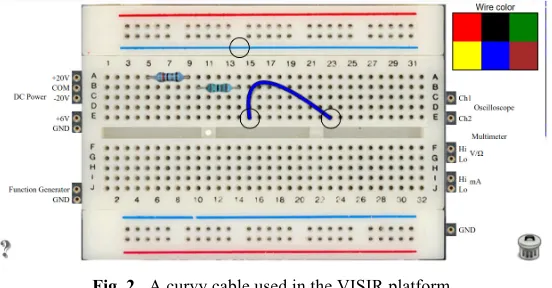
A more advanced solution has been used in the VISIR platform, which has been reused as a basis for many virtual labs [3,4,5]. The cables are represented with three nodes, two of which are “plugged” in the sockets. The third node is used to manipu-late the route of the cable (Figure 2). This approach offers a very realistic representa-tion of the cable in a 2DR2D environment, however it would still be inappropriate for a 2DR3D one, as there are more than one planes available, to which the cable should be connected.
Fig. 2. A curvy cable used in the VISIR platform.
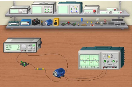
A significantly different approach has been used in 3DLab [6]. This is a 2DR3D environment, where the cables are freehand drawn during connection (Figure 3). This method is definitely better for an imitation of the 3D environment; however, the ca-bles look unrealistic and curvier than they are expected to be. With this approach, the look of the cable would much depend on the expertise of the user.
cable by dividing it into numerous sections. In Ref. [10] flexible cables were imple-mented with a mechanical model using their sagittal diameter, pitch angle, and deflec-tion angle. In all cases was achieved a very realistic visualizadeflec-tion of the 3D cables.
Fig. 3. The Freehand cable drawing method.
The available approaches for visualizing virtual cables in 2DR3D environments do not look realistic enough. On the other hand, the models used in pure 3D environ-ments are unnecessarily complicated for a 2D one. The goal of this study is to present a simple method for realistic visualization of virtual cables in a 2D environment, which is representing a 3D virtual reality.
2
MATERIALS AND METHODS
The main problem with the available methods for visualization of virtual cables in a 2D environment is that they are designed for a single plane. However, in a 3D reali-ty, multiple planes are available and as a result, the cables could be plugged into (coming out of) more than one 3D surface. This implies the need for their ends to be oriented towards the corresponding plane in order to look realistic. They should also have at least one degree of freedom.
The proposed method for visualization of virtual cables is based on Bezier curves. A cubic Bezier curve is described with four points P0, P1, P2 and P3, according to [11]:
( )
3( )
. 0 10
3 ! !
"
B t P; t= t
P i
=
i i
. (1)
( )
3. .( )
1 2 0,1,2,33 t t i;=
i = t
Bi "" i ! # $ %% &
' . (2)
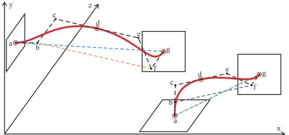
In the present study is suggested that each virtual cable can be implemented with two connected cubic Bezier curves, respectively marked as abcd and defg.
Fig. 4. Representation of virtual cables, attached to two different planes with two cubic Bezier curves.
Two situations are presented in Figure 4. In the first case, a cable connects two sur-faces, which are located in the XY and XZ planes and the 2D distance between the two sockets is ag. The virtual cable is represented with two cubic Bezier curves de-fined between the points a-d and d-g. The sections ab and fg are perpendicular to the two planes and their lengths are:
!" !!" !!"!. (3)
The divider m is a constant. Another important rule is that the sections cd and de are equal in length and are in parallel to the section bf:
!" ! !" !!"!. (4)
In equation (4) n is also a constant. In the second situation presented in Figure 4, the virtual lead connects two surfaces in the XY and YZ planes. The same rules apply to the sections of the cubic Bezier curves and the same constants m and n are used.
This study suggests that in order to have a realistic representation of the virtual ca-ble, the constants m and n should be carefully chosen. The cables will also have one degree of freedom, provided by the common point of the two curves - d.
3
Results and discussion
• Scenario 1: the two sockets are on the same 2D line and on the same 3D plane
(Figure 5a);
• Scenario 2: the two sockets are on the same 2D line but on different 3D planes
(Figure 5b);
• Scenario 3: the two sockets are on different 2D lines but on the same 3D plane
(Figure 5c);
• Scenario 4: the two sockets are on the different 2D lines and on different 3D
planes (Figure 5d).
a) b)
c) d)
Fig. 5. Test scenarios depending on the 2D line and 3D plane of the sockets: a) Scenario 1; b) Scenario 2; c) Scenario 3; d) Scenario 4.
An experiment has been carried out in CorelDraw X5. The suggested cable model with two cubic Bezier curves has been implemented as a curve with three nodes where for the middle one is selected the “Symmetrical” option. Different values for the constants m and n have been used in numerous experiments. The following values of the constants were chosen as optimal in order to provide realistic visualization of the virtual cables:
m=7 and n=3.5 (5)
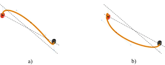
The results of the four scenarios with the chosen constants are presented in Figure 6, Figure 7, Figure 8 and Figure 9. In order to test the degree of freedom of the cables, different locations of the common point d (the middle node) are presented for each scenario. From the obtained results can be seen that the proposed method ensures a very realistic representation of the virtual cables in a 2DR3D environment. The change in the position of the common point d does not spoil the sense of 3D reality, because even though the cables go through different parts of the 2D space, they keep their orientation near the sockets perpendicular to the corresponding 3D planes.
seen, the suggested model is very powerful in terms of controlling the route of the cables and offers easy manipulation via their common point d. This does not affect the sense of reality and allows to avoid cable overlapping.
a) b)
Fig. 6. Different positions of the common point d for Scenario 1.
a) b)
Fig. 7. Different positions of the common point d for Scenario 2.
a) b)
Fig. 8. Different positions of the common point d for Scenario 3.
a) b)
Fig. 10.Implementation of the virtual cables in the EVEEE environment.
4
Conclusion
In the present study, a new model for visualization of virtual cables has been pre-sented. It is applicable in 2D environments, which represent 3D virtual reality. Two consecutive cubic Bezier curves abcd and defg represent the cables. The starting sec-tion ab and the ending section fg are perpendicular to the two planes, to which they are attached and the sections cd and de are parallel to the section bf.
An experiment was carried out in CorelDraw in order to determine the appropriate parameters of the Bezier curves. The optimal lengths of the sections were obtained to be ab=fg=ag/7 and cd=de=ag/3.5. The performed experiments and the obtained re-sults showed that the change in the position of the common point d does not spoil the sense of reality of the virtual cables. The model has been implemented in the EVEEE platform.
5
Acknowledgment
This work is supported by the University of Ruse Research Fund under contract no. 2018-RU-02 “Development of a web-based platform for virtual reality in the field of electrical engineering”.
6
References
[1]Autodesk Circuits website: https://circuits.io
[3]L. Claesson, L. Håkansson, “Using an Online Remote Laboratory for Electrical Experi-ments in Upper Secondary Education”, International Journal of Online Engineering (iJOE), vol. 8, pp. 24-30, 2012. http://dx.doi.org/10.3991/ijoe.v8iS2.1941
[4]R. Salah, G. Alves, P. Guerreiro, I. Gustavsson, “Using UML Models to Describe the VISIR System”, International Journal of Online Engineering (iJOE), vol. 12, no.6, pp. 34-42, 2016. http://dx.doi.org/10.3991/ijoe.v12i06.5707
[5]S. Odeh, M et al., “Assessing the Remote Engineering Lab VISIR at Al-Quds University in Palestine”, International Journal of Online Engineering (iJOE), vol. 11, no. 1, pp. 35-48, 2015. http://dx.doi.org/10.3991/ijoe.v11i1.4219
[6]3DLab website: https://www.circuitlogix.com/circuitlogix-3DLab.php
[7]E. Hergenröther, P. Dähne, “Real-time virtual cables based on kinematic simulation”, WSCG '2000: Conference proceeding: The 8th International Conference in Central Europe on Computers Graphics, Visualization and Interaktive Digital Media '2000 in cooperation with EUROGRAPHICS and IFIP WG 5.10: University of West Bohemia, Plzen, Czech republic, February 7 - 10, 2000, pp. 402-409, 2000.
[8]A. Loock, E. Schomer, “A Virtual Environment for Interactive Assembly Simulation: From Rigid Bodies to Deformable Cables”, 5th World Multiconference on Systemics, Cy-bernetics and Informatics, 2001, pp. 325-332, 2001.
[9]S. Nahavandi et al., “Haptics interface for modelling and simulation of flexible cables”, ICITA 2013: Proceedings of the Information Technology and Applications 2013 confer-ence, Sydney, N.S.W., pp. 6-11, 2013.
[10]B. You et al., “Study on Mechanics Performance of Flexible Spacecraft Cables Combined with Complicated Working Conditions”, International Journal of Hybrid Information Technology, vol. 7, no.5, pp.375-384, 2014. http://dx.doi.org/10.14257/ijhit.2014.7.5.34 [11]F. Zhou, B. Song, G. Tian, “Bézier Curve Based Smooth Path Planning for Mobile Robot”,
Journal of Information and Computational Science, vol. 8, no. 12, pp. 2441-2450, 2011.
7
Authors
Boris Evstatiev is an associate professor and Dr. in the University of Ruse Angel
Kanchev, Bulgaria. His research interests include modelling and simulation, virtual reality, software engineering, electrical engineering and energy ([email protected]).