Tribology in Industry
www.tribology.rsA Method for Predicting Contact Strength and Life of
Archimedes and Involute Worm Gears, Considering
the Effect of Wear and Teeth Correction
M. Chernets
aa Faculty of Mechanical Engineering, Lublin University of Technology, ul. Nadbystrzycka, 36, 20-618 Lublin, Poland.
Keywords:
Worm gear
Meshing of Archimedes and involute gears
Teeth correction of the worm wheel, Contact strength
Wear Gear life
A B S T R A C T
A new method developed by the author is used to investigate the effect of wear of worm wheel teeth on variations in their curvature radius and that of teeth correction in Archimedes and involute worm gears on their contact strength, wear and life. The effect of teeth correction on these variables is determined, for both constant and changed contact conditions. It has been found that when a positive correction coefficient is applied, the maximum contact pressures and wheel teeth wear decrease while the gear life increases; when the correction coefficient is negative, the trend is opposite. On changing contact conditions after wear limit of the teeth, the contact pressures are considerably lower, the gear life is practically the same, and the wear of worm wheel teeth is slightly higher than that in the case of constant conditions.
To accelerate calculations, the block-cumulative method developed by the author and not the specified step-by-cumulative method are used. The computational time is reduced proportionately to the size of the block of the number of interactions.
© 2019 Published by Faculty of Engineering
Corresponding author:
Myron Chernets
Faculty of Mechanical Engineering, Lublin University of Technology, ul. Nadbystrzycka, 36, Lublin 20-618, Poland.
E-mail: [email protected]
1. INTRODUCTION
Worm gears are widely used in machine design because they ensure considerable changes in torque and revolutions frequency with small dimensions. When gear elements are in mesh, sliding friction occurs, causing wear of the worm wheel teeth. It is vital to be able to predict gear life and wear of worm wheel teeth already the stage of gear design. Despite the obvious need for that, the methods for predicting abrasive wear of worm gear teeth given in the literature
[1-3] cannot be applied to uncorrected and corrected gears, especially at boundary lubrication. Based on elastohydrodynamic lubrication theories, the studies [1,2] report the results of prediction of teeth wear in an uncorrected gear by a modified Archard law, using a model allowing for variations in contact pressures and oil film thickness in contact area. However, it should be noted that the Archards law of abrasive wear used in the above-mentioned works, assuming linear dependence on slip velocity and contact pressures, in the
R
ES
EA
R
case of elastohydrodynamic and also boundary lubrication does not work.
Based on the author generalized method for prediction of wear at sliding friction (dry, mixed, boundary) [4], where the mechanism of fatigue wear is assumed, which has been confirmed by the works of the author as well as in literature by other researchers, the author developed a method [5] enabling prediction of contact parameters, worm wheel teeth wear and gear life. This paper reports the results obtained with the proposed method with respect to determination contact and tribological variables describing Archimedes and involute worm gears, considering the effect of teeth wear and correction on these parameters.
2. MATEMATICAL MODEL OF WEAR AT
SLIDING FRICTION
In worm gears, at oil lubrication, sliding friction occurs between the worm coils and the worm wheel teeth at torque transfer. Assuming that the wear rate of the elements of the tribosystem (see - the left side of equation (1)) is functionally related to the level of specific friction force (right side of the equation), the kinetics of wear in a sliding tribological system is described by a system of linear integer equations [4]:
1
d 1
( ), d
kj k j
h
v t
k1;2. (1)
Experimental values of the function are approximated by the following formula:
ms
C / k
k k k
(2)
where sk0.35Rmk.
The experimental values of functions are determined as follows [4]:
/ ,i i L hi
(3)
where Lvt.
The unit friction force is described by the Amontons-Coulomb law of friction:
j fpj
(4)
The maximum contact pressured pj pjmax is
determined with the Hertz formula, depending
on the number of meshing pairs w of the worm
wheel teeth:
max 0.564 /
w
j j
p N w b (5)
where
2
2
1 1 2 2
1 /E 1 /E
.
2.1 Linear wear of the worm wheel teeth (pjmaxconst)
By integration of equation (1), considering function (2) and formulas (4), (5) and assuming that the contact pressures const, we get a formula for calculating unit linear wear of gear teeth during a single time of tribocontact interaction:
2
2 m
max
2 m
2 s2
C
w
j j j
j
t fp
h
(6)
where ( )
2 w /
j j j
t b v .
According to the Hertz formula:
( )
2bjw 2.256 ΘNj/bw
The sliding rate is:
2 2
( ) ( )
j j j
v v v (7)
Accordingly,
1
A
cos
j
x
(8)
where tgA mz1/ 2x, 1 n1/ 30.
pA 2
j e j
, 21/u (9)
It should be noted that the dominant effect on the resulting slip speed is velocity v.
The meshing force N is determined by the
formula:
1 p
2
cos xjsin( )
T N
d
(10)
where:
3 1
9550 10 ( / )
T N n and
/ cos
arctg f
.
2
pA
( sin )
2
j xj j
d
e
(11)
the involute worm is:
1 2 1 2 j j j j j
(12)
The curvature radius of involute worm thread profiles 1j and worm wheel teeth 2j.
b c
1 3 2
p b c
cos cos
j j
xj j j
r tg tg 2
1 2 p 1 pA pA
2
2 p 1 pA
sin
sin
j xj j j j
j
xj j j
r e e
r e
(13)
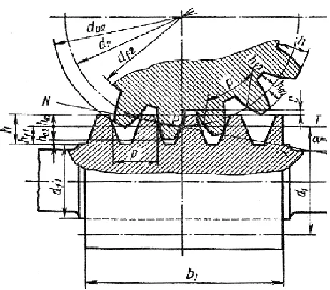
The worm wheel teeth have involute profiles (Fig. 1).
Fig. 1. Schematic design of a worm gear.
The coordinate x is in the range of xAxxB.
Accordingly x r 0.2m 1
f
A and xB ra1.
The section of meshing [xA,xB] must be
proportionately divided into smaller sections:
A A 1, 2 2
x j j x j , x3 j3, ... and
B
n j
j
xB .
3. GEAR GEOMETRY
The geometry of the analysed worm gears (Fig. 1) is described by the following relationships:
1 1 1
f 0.5 1 2 f , f 1.2
r d h h m
(where 15 ),
1
f 1.2 n
h m (where 15 );
1 1
tan mz d/ , d1qm;
1 1 1
a 0.5 1 2 a , a
r d h h m
(where 15 ),
1
a n
h m (where15 );
2 2 2 2
2 1 2
0.5 , 0.5 ,
, 2 1
r z m r d
z uz q z
;
1
pA 1 1
p
, 0.5 , 2 1
sin
j
xj
r x
e r d b m q
.
Other geometrical parameters:
- Archimedes worm gear:
1 p
180
arctan( tan ), tan ,
2
xj xj xj
mz x
- Involute worm gear:
b 0.5 1cos c
r d , tanctann/ sin ,
2 2 b c b arctan j x r r , 2 2 b
pxj arctan tan b
x r x , 1 b 1 c tan cos mz d , 2 2 b b 180 j x r r .
4. LINEAR WEAR OF TEETH AND LIFE OF THE WORM GEAR (pjmaxconst)
The wear of the worm wheel teeth within one hour of gear operation is calculated in the following way:
h2j 60n h2 2j, n2n u1/ (14)
The life of the worm gear for the acceptable wear h2 of the worm wheel teeth is calculated
according to the formula:
t
h2/h2j
(15)
5. LINEAR WEAR OF THE WORM WHEEL
TEETH (pjmax var)
2
2 m
max
2 m
2 s2
C
w
j jh jh
jn
t fp
h
(16)
As a result, the radius of curvature of the teeth increases with every revolution of the worm wheel, and the maximum tribocontact pressures decreases with increasing the width of the contact area. Accordingly,
max 0.564 θ
jh jh
p N bw ρ ,
2bjh2.256 θN ρ jh bw (17)
where jh=2jh - Archimedes worm gear,
1 2
1 2
j jh jh
j jh
- involute worm gear,
2 /
jh jh j
t b v .
5.1 Definition variations in teeth curvature radius due to wear
The proposal of a method is to determine the effect of linear wear of gear teeth on the curvature radius. The variable curvature radii 2jh of teeth profiles at j-th point of contact are expressed:
2 2 2 2
n
jh j h jn
ρ ρ λ
h (18)Therefore, for numerical resolution, a step-by-step calculation of the following parameters is performed: h2jn, ρ2jh, ρjh, pjhmax, 2bjh, tjh.
To accelerate the calculations, it is expedient to use the block-cumulative method developed by the author and not the specified step-by-cumulative method. This method is based on an assumption that, during a given number of wheel revolutions n2 (interaction block B), the
parameters h2j, pjmax, 2bj, tj are constant. A
subsequent block allows for a change in these parameters due to wear, and so the calculations are made for new values. The computational time is reduced proportionately to the size of the block of the number of interactions. For example, in the given solution (item 8) when the block size is B=10
60n u1/
=33177 revolutions,then this time will be 33177 times smaller than in the case of the step-by-cumulative method.
Hence, according to the block-cumulative method variable curvature radii:
ρ2jhρ2j λh
B h2jn (19)
6. TOTAL WEAR AND LIFE OF THE WORM GEAR (pjmaxvar)
The total wear of worm wheel teeth determined by the above step-by-cumulative and block-cumulative methods is:
2
2 2
1
n
jn jn
h h
, 2 2 21
n
jn jB
h
h
, (20)where
h
2jB
h
2
j .The gear life after revolutionsn2 of a worm
wheel when acceptable wear is reached:
2 / 60 2
t n n . (21)
7. WORM WHEEL TEETH CORRECTION
In worm gears, we can only apply correction to the worm wheel teeth.
The interaxial distance is:
ak a x m2 (22)
where a(d1d2) / 2, x2 1.
The reference diameter of the worm in an uncorrected gear:
dw1d1x m2 (23)
Therefore, the distance
e
pAj between the j-thpoint of contactand the point of contact will be:
w1 pA
p
. sin
j j
xj
r x
e
Other geometrical parameters are determined in accordance with the formulas for uncorrected worm gears.
8. NUMERICAL SOLUTION
hardened steel grade 45 (HRC 50) described by
1
E = 2.1105 MPa, μ1= 0.3; worm wheel ring –
bronze CuSn6Zn6Pb6 described by E2 = 1.1105
MPa, μ2= 0.34; C2 = 7.6106,
2
m = 0.88; τs2 = 75
MPa; for j = 1; 2; 3; 4 and 5, respectively x = 18; 20; 22; 24 and 26 mm; h2*= 0.5 mm; λh = 100; B= 10
60n u1/
= 33177 revolutions (10 hoursof work); with double-pair meshing.
The numerical results are given in Figs. 2–7: а) Archimedes worm gear, b) involute worm gear. Solid lines denote constant conditions of contact, broken lines mark variations in the reduced curvature radius due to wear.
0 50 100 150 200 250
-1 -0.5 0 0.5 1 x2
pm
a
x
,
M
P
a
j=1 j=5
j=1.1 j=5.1
a)
0 50 100 150 200 250 300 350 400
-1 -0.5 0 0.5 1 x2
pm
a
x
,
M
P
a
j=1 j=5
j=1.1 j=5.1
b) Fig. 2. Wear and correction versus pmax: – pmax
when j = 1; – pmax when j = 5.
Figure 2 shows the relationships between the maximum contact pressures pmax and the
displacement coefficient x2 on entering the
mesh (j = 1) and on leaving the mesh (j = 5). It was found that the positive correction of the worm wheel teeth leads to reduced pressures, while the negative correction results in their increase compared to the observations made regarding the uncorrected gear. This results in an increase in the teeth curvature summary
radius ρz ρ at their acceptable wear h2*= 0.5
mm when
x
2 is positive and it decrease atnegative values (Fig. 5).
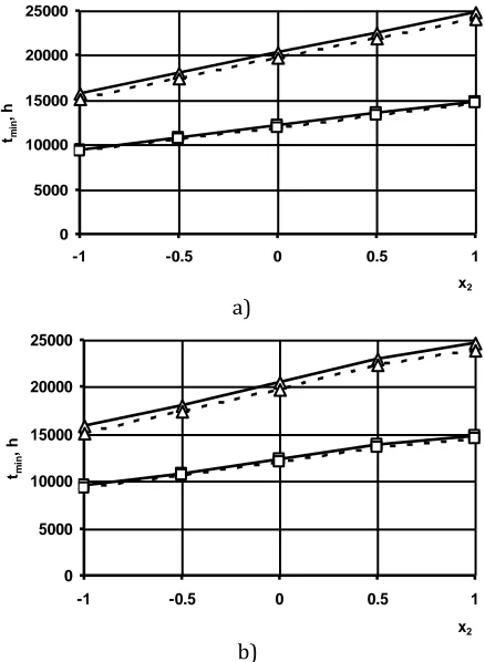
As a result of the applied teeth correction, when
2 0
x , and z increase and the gear life tmin
increases too (Fig. 3). When x20, andz
decrease, which leads to reduced gear life. Taking into account the teeth wear, the gear life will be slightly shorter than that in the case with constant conditions of interaction.
0 5000 10000 15000 20000 25000
-1 -0.5 0 0.5 1 x2
tmin
, h
tmin (0.3) tmin (0.5)
tmin (0.3) 2 tmin (0.5) 2
a)
0 5000 10000 15000 20000 25000
-1 -0.5 0 0.5 1 x2
tmin
, h
tmin (0.3) tmin (0.5)
tmin (0.3) 2 tmin (0.5) 2
b)
Fig. 3. Wear and correction versus gear life tmin: – min
t whenh2*= 0.3 mm; – tmin whenh2*= 0.5 mm.
The linear wear of gear teeth during one hour of operation, with contact conditions maintained constant (friction path 2bj), will be lower than
under variable contact conditions (friction path
2bjh) due to wear (Fig. 4). When positive
correction coefficients x2are applied, the wear h2
is lower (Fig. 4) than that of the uncorrected gear.
As a result of teeth wear, the curvature radii 2 of
1.70E-05 2.20E-05 2.70E-05 3.20E-05 3.70E-05
-1 -0.5 0 0.5 1
x2
h2
,
m
m
ħ2max ħ2min
ħ2max 2 ħ2min 2
a)
1.70E-05 2.20E-05 2.70E-05 3.20E-05 3.70E-05
-1 -0.5 0 0.5 1
x2
h2
,
m
m
ħ2max ħ2min
ħ2max 2 ħ2min 2
b) Fig. 4. Wheel teeth wear per hour versus change in
2
x : – h2max when j = 1; – h2min when j = 5.
0 40 80 120 160
-1 -0.5 0 0.5 1 x2
p2
,
m
m
P2max P2min
P2max 2 P2min 2
a)
0 40 80 120 160
-1 -0.5 0 0.5 1 x2
p,
mm
P2max P2min
P2max 2 P2min 2
b)
Fig. 5. Wear and correction versus curvature radii change: –2max (max) when j = 1; –2min (min)
when j = 5.
In both gear types, the sliding rate does not change at j-th contact points, in either constant or variable conditions of interaction (Fig. 6).
2 2.5 3 3.5 4
1 2 3 4 5
j
Vj
, m
/s
Ряд1 Ряд2 Ряд3
Ряд4 Ряд5
Fig. 6. Variations in sliding rate over tooth height.
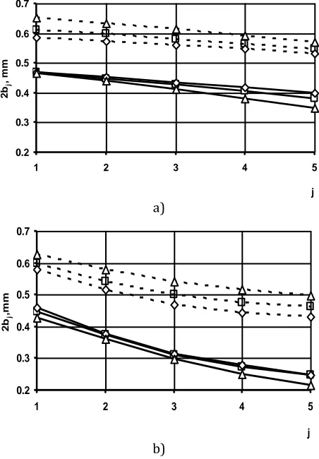
The effect of gear teeth correction on the contact area width 2bj is insignificant when
max, 2 j
p b const; the value of 2bjh is affected
more significantly when pmax, 2bj var due to
wear of the worm wheel teeth (Fig. 7). The contact area width considerably increases due to wear of the gear teeth.
0.2 0.3 0.4 0.5 0.6 0.7
1 2 3 4 5
j
2b
j
,
m
m
x=0 x=0
x=1 x=1
x=-1 x=-1
a)
0.2 0.3 0.4 0.5 0.6 0.7
1 2 3 4 5
j
2b
j
,m
m
x=0 x=0
x=1 x=1
x=-1 x=-1
b)
Fig. 7. Wear and correction versus contact area width during one interaction between tooth and worm coil:
The proposed method can be used to establish qualitative and quantitative relationships with respect to the effect of teeth correction and wear on the load capacity, life, wear, sliding velocity and contact area widthof the worm gear.
9. CONCLUSION
1. It has been found that, in contrast to uncorrected gears, the maximum contact pressures decrease when the correction coefficient x2 is positive. When this
coefficient is negative – the pressures increase (Fig. 2).
2. The life of the worm gear increases at
2 0
x but decreases at x20(Fig. 3).
3. The wear of the worm wheel teeth decreases at x20 and increases at x20,
in contrast to the case when x2 0(Fig. 4).
4. The tooth curvature radii increase with increasing х2 and they decrease with
decreasing x2 (Fig. 5).
5. Gear correction does not have a significant impact on the contact area width.
6. Negative correction leads to decreased load capacity and life of the worm gear and increased wear of worm wheel teeth, hence it is not recommended.
REFERENCES
[1] K.J. Sharif, H.P. Evans, R.W. Snidle, D. Barnett, I.M. Egorov, Effect of elasto-hydrodynamic film thickness on a wear model for worm gears, Proceedings Institutions Mechanical Enginers, Part J: Journal Engineering Tribology, vol. 220, pp. 295– 306, 2006, doi: 10.1243/13506501JET122 [2] K.J. Sharif, H.P. Evans, R.W. Snidle, Prediction
of the wear pattern in worm gears, Wear, vol. 261, iss. 5-6, pp. 666–673, 2006, doi:
10.1016/j.wear.2006.01.018
[3] H.G. Sabiniak, Wear and life of the worm gears.
Publishing House of Lodz University of Technology: Lodz, 2007.
[4] M.V. Chernets, J. Kelbinski, R.Ja. Jarema, Generalized method for the evaluation of cylindrical involute gears, Materials Science, no. 47, pp. 45 – 51, 2011,
doi: 10.1007/s11003-011-9366-9
[5] M.V. Chernets, R.Ja. Jarema, Prediction of the life of the worm gears in Archimedes and involute worm gears, Problems of Tribology, no. 2, pp. 21–25, 2011.
NOMENCLATURE
a
is the interaxial distance in an uncorrected gear,2
b is the worm wheel width,
С ,mk k are the indicators of wear resistance of tribological pair materials in select wear conditions,
1
d is the reference diameter of the worm,
2
d is the reference diameter of the worm wheel,
pA
e is the distance of j point from the contact point,
f is the sliding friction coefficient,
q is the diametric quotient of the worm gear,
k
h is the linear wear of elements of a tribological pair,
i
h consumption of samples of tribological vapor
materials,
1 f
h is the height of worm thread base,
a1
h is the height of head of the worm coil,
2jn
h is the linear wear of teeth during a single
interaction, decreased due to changes in 2jh,
jh
t , pjhmax,
2jB
h is the wear of teeth during a block of interaction,
*
h2 is acceptable wear the teeth of the worm wheel, i load level,
j point of contact between elements of a kinematic pair (worm – worm wheel tooth),
k denotes the number of an element of the
tribological pair (1 – worm, 2 – worm wheel),
L the road of friction,
m is the axial modulus of meshing,
cos
n m
m is the normal modulus of meshing,
2
n is the number of revolutions of the worm wheel
per minute,
2
n is the number of revolutions of the worm wheel
when the acceptable worm wheel teeth wear h2*
N is the meshing force, N is the transmitted power,
1
n is the number of revolutions of the worm,
max
j j
p p are the maximum contact pressured
determined with the Hertz formula, depending on the number of meshing pairs w of the worm wheel teeth,
max
jh
p are the maximum current tribocontact
pressures.
m
R is the temporary tensile strength of materials,
f1
r is the radius of a circle of worm cavity,
a1
r is the radius of a circle of worm coil prongs,
b
r is the radius of a basic circle of worm coils, t is a period of wear,
j
t is the time of contact between the meshing elements at j-th point on the friction path with a length equal to the contact area width ( )
2
b
jw , T is the torque transmitted by the worm, u is the gear ratio, is the sliding rate at j-th point of contact between elements of a kinematic pair,
j
is a sliding rate during worm gear revolution,
j
is a sliding rate at the point of contact between the worm wheel tooth and worm coil,
w is the number of meshing pairs between worm coils and worm wheel teeth,
2
x is the correction coefficient,
1
z is the number of worm coils,
2
z is the number of teeth in the worm wheel,
n
is the angle of meshing,
c
is a face pressure angle,
cj
is the face pressure angle at j-th point,
is the angle of elevation of the screw line of worm coils,
b
is the angle of inclination of flank pitch line on reference diameter of the gear,
is an angular coordinate in every pitch (degrees),
is the characteristic function of wear resistance of tribological pair materials under select conditions,
h
λ is a non-dimensional coefficient of wear impact,
μ ,Ek k are Poisson’s ratio and Young’s modulus of material of the worm wheel, respectivity,
j
is the reduced curvature radius between worm coils and worm wheel teeth at j-thpoint of meshing,
z
ρ is the reduced radius of curvature of the worm gear,
ρ is the reduced radius of curvature of the involute worm gear;
jh
is the reduced radius of curvature of the involute worm gear a result of the wear tooth; wear of the steel worm is omitted,
jh
2
is the radius of curvature of the Archimedes worm gear,
is a friction angle,
is the unit friction force affecting wear rate of materials,
sk
is the temporary shear strength of gear material,
θ is the Kirchhoff modulus,
1