Design and Implementation of an Audio Processing
System for Pipelines Gas Leakage Detection
Lugain Sadik Hyal
Hussein Majeed Salih
Thamir Rasheed Saeed
* Electromechanical Eng. Dept.,University of Technology- Iraq. University of Technology- Iraq. Electromechanical Eng. Dept., University of Technology- Iraq. Electrcal Eng. Dept.,
Date of publication (dd/mm/yyyy): 12/02/2017
Abstract — The pipelines are a frugal and safe way to transport gasses, oil, and other petrochemical materials. Many problems may occur in pipelines while the leak is one of the most frequent problems and must be dealt with it. The present work has presented a simulation and practically analysis of underwater gas leak detection system. Numerically, the governing equations are discretized by a finite volume method by using a staggered (non-collocated) arrangement of the variables. The solutions are obtained using the SIMPLE algorithm with UDS and CDS. A microphone array has been implemented for leakage detection. Experimentally, the results are carried out for inlet air velocity range of 5,8,11 m/s for three pipes with a length of 1 m and diameter of 8mm at a different diameter of leak 2,4,8 mm. The results have been showed the matching between the simulation and practical measurement of the accuracy of the leak detection and location determination on these pipes at three levels of measurements, under, at, and over the water level with different flow rate.
Keywords — Acoustic Emission, Leak Detection, Leakage Test, Arduino Application, Gas Pipeline.
I.
I
NTRODUCTIONPipelines are the oldest and widely used medium for transportation and distribution water, crude oil, oil products, natural gas and other products from one place to another. The pipelines are exposed to a lot of problems due to different factors and because of continuous usage. So, Leakage is one of the pivotal issues to be dealt with to promote the efficiency and validation of the work with pipelines. Leakage occurs due to several of external factors such as poor pipe material, disfiguration of the pipeline, operational errors and erosion of pipe walls [1]. A various leak detection methods are utilized to monitor the pipeline such as methods based on mass/volume balance, Statistical method Gas sampling device method, optical methods, transient real-time modeling and acoustic method[2]. Among these, acoustic emission has been showed to be the most powerful, effective and non-devastating testing technique offers a very effective solution for detecting and locating known or suspect leaks in buried pipelines [2]. Where, the basic principle of Acoustic emission method to detection the fault in fluid flowing pipelines because of turbulent velocity fluctuations during flow are the cause of sound excitation and if the fluid escape through a leak in a pipe wall different turbulent characteristics than the normal condition is to be identified.
Numerous studies on leak detection using acoustic method has been presented. Watanabe, et al. [3] was
measured the acoustic wave conducted at the two ends of the pipeline, which is showed a clear positive or negative pulse at a certain time that can be used for determination of the leak location. While Hunaidi [4] and Min-Soo et al. [5] was studied the distributions characteristics of the frequency band of acoustic signals in a water distribution pipeline. Also, Min-Rae et al. [6] and Zhao Yang et.al [7] has presented an observing of the leak in pipelines using acoustics and hydromechanics method by using the wavelet transform (WT). Where, Liying Sun et.al [8] was showed the use of a pressure of pipes during normal operation with a relative error is nearly 2.63%. In this context, Liang Wei et al.[9] and A. Mostafapour [10], Presented a model acoustic emission generated by the pipe vibration due to leakage. A five microphone array with Arduino as the interface has been presented in this work to detect the leak of the underwater pipeline system. Experimentally, the results are carried out for inlet air velocity range of 5,8,11 m/s for three pipes with a length of 1 m and diameter of 8mm at different leakage size 2,4,8 mm. The results have been showed the matching between the simulation and practical measurement of the accuracy of the leak detection and location determination on these pipes at three levels of the microphone array; under, with, and over the water level with different flow rate.
II. P
ROPOSEDG
ASL
EAKD
ETECTIONS
YSTEMThe proposed system was based on the detection of the leak through microphone array. The experimental operation of the proposed system has been made using a basin with dimensions (1×0.5×0.5 m) with three pipes, 1m with 8mm diameter for each one. In this context, it was made a hole (for leak representation) for each pipe with dimension 2, 4, and 8 mm as shown in figure (1-a,b).
(B)
Figure 1 Experimental apparatus of the proposed system; (a) block diagram, (b) system pic in laboratory
A.
Analysis of the Proposed System
The analysis of the proposed system contains two phases; theoretical (inside and outside of the pipeline ) and practical of the flow.
Figure.2 Physical model
a. Inside Analysis of the pipe
Figure.2 shows the physical flow mode in pipes of the proposed system. The working fluid (air) is allowed to flow forcibly inside the pipeline by an air compressor. Consider a laminar flow through pipeline. It is assumed that the flow inside pipes is steady, incompressible and ax-symmetric. The fluid is assumed to have constant physical properties. The equations of continuity, momentum can be written as follows:
Continuity equation (mass conservation[11])
𝝏
𝝏𝒙(𝝆𝒖𝒓) + 𝝏
𝝏𝒓(𝝆𝒗𝒓) = 𝟎 (1)
u-momentum(x-direction) v-momentum (r-direction) The governing equations are discredited by a finite volume method which is widely used. The more common complex geometries can be modeled when generalized coordinates are used. Fashion using a staggered (non-collocated) arrangement of the variables. The solutions were obtained using the SIMPLE algorithm with UD and CD schemes. A computer program in FORTRAN 90 is written to solve a set of the partial differential equations that govern the fluid flow in the pipes. At inlet boundary condition, the values of dependent variables are identified and subsequently known. The boundary condition at inlet is: u1,j = uin, v1,j = 0 The final expression for the governing Eq. is[12]: 𝐚𝐞𝛗𝐄+ 𝐚𝐰𝛗𝐖+ 𝐚𝐍𝛗𝐍+ 𝐚𝐬𝛗𝐒= 𝐚𝐩𝛗𝐩 (4)
The coefficients of this equation are as follows: 𝐚𝐞 = 𝐦𝐚𝐱 [(𝐃𝐞−𝐅𝟐𝐞) , −𝐅𝟐𝐞)] (5)
𝐚𝐰= 𝐦𝐚𝐱 [(𝐃𝐰−𝐅𝟐𝐞) , −𝐅𝟐𝐞)] (6)
𝐚𝐍= 𝐦𝐚𝐱 [(𝐃𝐍−𝐅𝟐𝐧) , −𝐅𝟐𝐍)] (7)
𝐚𝐬= 𝐦𝐚𝐱 [(𝐃𝐬−𝐅𝟐𝐬) , −𝐅𝟐𝐬)] (8)
𝐚𝐩= 𝐚𝐞+ 𝐚𝐰+ 𝐚𝐧+ 𝐚𝐬 (9)
𝐒𝐩= 𝐅𝐞− 𝐅𝐰+ 𝐅𝐧− 𝐅𝐬 (10)
The values of convection and diffusion coefficient are calculated by the following formula: De/Dw/Ds/Dn = μA/𝛅 (11)
Fe/ Fw/Fs/Fn =𝛒𝐀𝐮 b. Outside Analysis of the pipe At outside of pipe the second order wave equation 1-d has been solved by using finite difference (leap frog method). The wave equation is[13]: 𝛛𝟐𝛗 𝛛𝐭𝟐
= 𝐜
𝟐 𝛛 𝟐𝛗 𝛛𝐱𝟐(12)
This equation has been solved using finite difference ((Leapfrog method)).gives: 𝐮𝐢𝐧+𝟏= 𝐮𝐢+𝟏𝟐𝐜𝟐(𝐮𝐢−𝟏𝐧 − 𝟐𝐮𝐢𝐧+ 𝐮𝐢+𝟏𝐧 ) (13)
𝐁. 𝐂 𝐮 = 𝐮𝐦𝐬𝐢𝐧(𝐤𝐱 − 𝐰𝐭) (14)
𝐩 = 𝐩𝟎𝐜𝐨𝐬(𝐰𝐭 ± 𝐤𝐱) (15)
In sound waves, the intensity is given by [14]: 𝐈 = 𝐩. 𝐮 (16)
B.
Experimental (Practical) Analysis
the Arduino (Mega 2560) between the microphone array and computer, which is used for analyzing the microphone array signals to determine the leak position.
When a gas flows through perforated pipes, the pressure inside the pipeline is interrupted, and the leakage has happened looks like bubbles. Then, the acoustic wave is generated due to the pipe wall and pipe media pressure friction. In this context, the detection system receives the acoustic waves to detect the leak and then determine its location.
The detection and the locating system have an array of microphones. This array has many advantages, one of them is to eliminate the noise and interferences. While, the remaining noise, and interference of the environments have been eliminated by subtracting from the received signal of leaks. The array factor is given by[15][16]:
𝐀𝐅 = ∑𝐍 𝐞𝐣(𝐧−𝟏)𝛙
𝐧=𝟏 (20) 𝐖𝐡𝐞𝐫𝐞:
𝛙 = 𝐤𝐝𝐜𝐨𝐬𝛉 + 𝛃 , N- Number of elements From this equation, it is obvious that the AFs of uniform linear arrays can be controlled by the relative phase β between the elements. For small values of ψ, the expression can be approximated by:
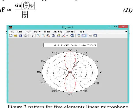
𝐀𝐅 ≈
𝐬𝐢𝐧[( 𝐍𝟐)𝛙]
[𝛙𝟐] (21)
Figure 3 pattern for five elements linear microphone array
The distance between microphone elements is reduced to 1 cm for decreasing the physical distance of array and compensate its effect by inserting the delay at the input of each element according to its position. While the delay has calculated for each sensor as[17];
𝐓𝐝𝐞𝐥𝐚𝐲 = (𝐝𝐦𝐢𝐜∗ 𝐜𝐨𝐬𝛉)/𝐜 (22) Where:
𝐝𝐦𝐢𝐜 - microphone spacing.
𝐜- wave seed, and can calculated as[18];
𝐂 = 𝟏𝟒𝟒𝟖. 𝟗 + 𝟒. 𝟓𝟗𝟏𝐓 – 𝟓. 𝟑𝟎𝟒 ∗ 𝟏𝟎−𝟐 𝐓𝟐+ 𝟐. 𝟑𝟕𝟒 ∗ 𝟏𝟎−𝟒 𝐓𝟑+ 𝟏. 𝟑𝟒𝟎(𝐒 − 𝟑𝟓) + 𝟏. 𝟔𝟑𝟎 ∗ 𝟏𝟎−𝟐𝐃 + 𝟏. 𝟔𝟕𝟓 ∗ 𝟏𝟎−𝟕 𝐃𝟐 − 𝟏. 𝟎𝟐𝟓 ∗ 𝟏𝟎−𝟐 𝐓(𝐒 − 𝟑𝟓) − 𝟕. 𝟏𝟑𝟗 ∗ 𝟏𝟎−𝟏𝟑 𝐓𝐃𝟑 (23) Where:
T- water temperature(in Celsius degree =25℃)
D- depth of water in meter (25cm) S- salinity (in part per thousand =0.4 PPt)
Therefore, the delay time is different in value depending on the position of microphone array from the surface of water basin if it is above, under or at water level. Then, the position of the leak has been determined at three levels of a microphone array on the water level ( upper, under and at the water surface).
III. R
ESULTS ANDD
ISCUSSIONThe results of the simulation and experimental testing of the proposal system have appeared the positions of the leaks in the gas pipeline. The experimental testing have been included many scenarios for three pierced pipelines at 40 cm, 50 cm, and 60 cm with 2 mm, 8 mm, and 4mm hole diameters respectively, three microphone array levels; upper, with, and under the water level, and three air flow for each pipeline with each microphone levels 1, 2, and 2,5 𝐦𝟑/𝐦𝐢𝐧. Figure 4 represent the sample of the results of the first pipeline
(a)
(b)
(d)
(e)
Figure 4 practical and simulation results of the first pipeline with air flow 1 m^3/min and hole size 2 mm; a) microphone array upper, b) under, c) with the water level,
d) velocity vector, e) the distribution of pressure in the first pipe.
Also, for the other pipelines and with different air flow at the microphone array upper, with, and under the water level. In this context, the noise signal level at the array microphone upper the water level is more strength than in the other two cases (under and with water surface), because the interferences and noise sources are more than the other cases.
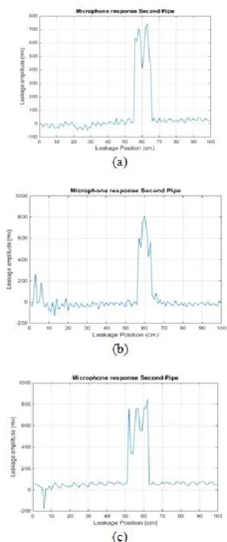
While the signal of microphone array of the second pipeline with hole 8 mm at 50 cm is more strength than the first as shown in figure 5.
(c)
Figure 5. practical and simulation results of the second pipeline with air flow 1 m3/min and hole size 8 mm; a) velocity vector, b)microphone array upper, under, c) the
distribution of pressure in the second pipe.
Also, the third pipeline with 4mm hole at 60 cm has a signal strength less than the second and more than the first one. In this context, the amount of leakage and then the signal strength have been increased with increasing the value of the flow rate as shown in figure 6.
Figure 6. practical results of the third pipeline with air flow 1, 2, and 2.5 𝐦𝟑/𝐦𝐢𝐧 at a,b, and c respectively and
hole size 4 mm.
The numerical results have been obtained to study the behavior of flow and pressure inside the pipes due to the presence of leak using FORTRAN 90 program. From results the pressure at initial (pipe wall) is the highest because of the speed wall pipe is equal zero, but the pressure will be interrupted at leak place because the pressure is as less as possible due to increasing the speed of flow at this point and then begins to increase.
hole at the outer surface of pipe and angle of hearing as shown in figure 7.
Figure 7. Intensity of sound at nominated time
A.
Effect of current of water on leakage detection
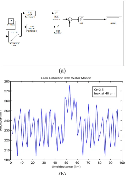
The water of the rivers and seas contain sometimes water currents generated inside it. These currents have different velocities depending on environmental conditions. Currents will effect on the path bubble emerging from leak point and cause to deviate from its path. Thus, affect the determination of the real location of the leak. An appointed mechanism is made a mechanism to demonstrate the impact of these currents. A practical and simulation of this effect have been made by water moving and Matlab Simulink as shown in figure 8-a while the effect of water motion on the leak position detection are in figure 8-b.(a)
(b)
Figure 8. effect of the water motion on the leak detection
The robustness of the proposed system depends on the reduction of the error in leakage detection measurements. As shown in Figure 9 below;
Figure 9. Microphone of the third pipe (leak at 50 cm)
The location of the leak detection has been made by three algorithms, threshold, maximum, and mid values. The usage of these algorithms on the real location of the leak is at 50 cm, as in the figure above. When to use the threshold algorithm has an error nearly15%, where the detection by this algorithm are limited between point C and D, then the location position is 44cm to 56cm. While when using the maximum algorithm the location is indicated at point M at 54 cm with related error 10%. In this context, when to use the mid value algorithm the location is a mid value of points C and D, and the related location is point R, and the related error is nearly 1%. Therefore, the resultant location of the leak is as table (1)
Table (1) measurements accuracy pipe Real location Mid value
location percent Error
1 40 cm 39 cm 2
2 60 cm 62 cm 2
3 50 cm 50 cm 0
For all pipes Average error percent = 2-3%
IV. C
ONCLUSIONSLeaks are considered one of the important problems in transmission pipelines. Therefore, the detection and then treatment of these leaks considered very importantly also. Many techniques have been used to detect the pipeline leakages, while, the acoustic technique has many features can be concluded, these are;
1- The acoustic technique has been considered as a simple and passive technique.
2- The use of an array has performed and accuracy in detection by producing a narrow beam.
3- The detection of leakage location by using microphone array is less cost than other techniques of detection.
4- The usage of ARDUINO as interface device due to simplicity micro-control and open code system,
also, to being easy to deal and development. 5- There are a coupling between the analysis of
pressure and flow of velocity with the performance of gas on the pipe at leakage location.
6- The use of mid values algorithm to find the leakage location is more accurate than the other algorithm.
0 10 20 30 40 50 60 70 80 90 100
200 210 220 230 240 250 260 270
280 Leak Detection with Water Motion
A
m
pl
itu
de
(m
v)
time/dectance (1m)
R
EFERENCES[1] C.Nayak.," Fault Detection in Fluid Flowing Pipes Using
Acoustic Method"., International Journal of Applied Engineering Research, Vol. 9, pp. (23-28),2014.
[2] Hao Jin*, Laibin Zhang, Wei Liang, Qikun Ding, "Integrated
leakage detection and localization model for gas pipelines based on the acoustic wave method", College of Mechanical and Transportation Engineering, China University of Petroleum, Beijing 102249, China.
[3] Watanabe, K., Matsukawa, S., Yukawa, H., & Himmelblau, D.
M. (October 1986). Detection and location of a leak in a gas transport pipeline by a new acoustic method. AIChE Journal, 32(10), 1690e1702.
[4] Hunaidi, O., & Chu, W. T. (1999). Acoustical characteristics of
leak signal in plastic water distribution pipes. Applied Acoustics, 58, 235e254.
[5] Min-Soo Kim, Sang-Kwon Lee*., " Detection of leak acoustic
signal in buried gas pipe based on the time–frequency analysis"., Department of Mechanical Engineering, Inha University, pp(990–994),2009.
[6] Min-Rae Lee1, a and Joon-Hyun Lee., "A Study on
Characteristics of Leak Signals of Pipeline Using Acoustic Emission Technique"., Solid State Phenomena Vol. 110 (2006) pp 79-88.
[7] Zhao Yang , Zhuang Xiong and Min Shao,"A new method of
leak location for the natural gas pipeline based on wavelet analysis", Thermal Energy Research Institute, School of Mechanical Engineering, Tianjin University, Nankai District, Tianjin 300072, China, Volume 35, Issue 9,2010.
[8] LiyingSun, Yibo Li, Tiegen Liu, Shijiu Jin and Weikui, Leak
detection and position method for pressure piping using Acoustic Emission, Intelligent Control and Automation, 8425 – 8429,2008.
[9] Liang Wei, Zhang Laibin, Xu Qingqing, Yan Chunying.,"Gas
pipeline leakage detection based on acoustic technology"., China University of Petroleum, Beijing, China., 2012.
[10] A. Mostafapour, S. Davoudi., "Analysis of leakage in high-pressure pipe using acoustic emission method"., Mechanical Engineering Department, pp(335–342),2013.
[11] Arnal, M.P.”A General computer program for two-dimensional,
turbulent, re-circulating flows”, Report No. Fm-83-2, January 1983.
[12] Awbi, H.B.”Ventilation of Building,” London, 1998.
[13] Richard Feynman, Lectures in Physics, Volume 1, 1969,
Addison Publishing Company, Addison. [14] Sound Intensity". Retrieved 22 April 2015.
[15] F. Gross, Smart antennas for wireless communications, 1st ed.
McGraw-Hill, 2005.
[16] Virgilio Z´u˜niga Grajeda., Bio-inspired Optimization
Algorithms for Smart Antennas., The University of Edinburgh., June, 2011.
[17] Steven Bell., Acoustic Beamforming: System Theory and Requirements., IEEE and Nathan West, Student Member, IEEE. [18] Paul C. Etter.," Underwater Acoustic Modeling"., London.
Glasgow., An Imprint of Chapman & Hall, 2nd edition, pages(1-282),1996.
A
UTHOR'
SP
ROFILELugain Sadik Hyalwas born in Baghdad, Iraq, in Sept 1991. She received the B.Sc and M.Sc degrees both from Electromechanical Eng. Dept., University of Technology- Iraq in 2013 and 2016, respectively. From 2014 till now, she worked with the University of Technology- Electrical dept. group in acoustic process. Her major interests are in digital signal processing, based on FPGA.
E-mail: [email protected]
Hussein Majeed Salih was born in Baghdad, Iraq, in February 1965. He received the BSc in College of Engineering–Al-Mustansiriah University- Baghdad in 1992, while, the MSc and PhD degrees both from Al-Rashed College of Engineering and Science, Baghdad in 2000 and 2005, respectively. From 2004 till now, he worked with the University of Technology, Iraq, as a member of teaching staff. Currently, he is an Assistant Professor of Mechanical Engineering at University of Technology. His major interests are Numerical and Experimental Study of Turbine and heat transfer
E-mail: [email protected]
Thamir Saeed was born in Baghdad, Iraq, in February 1965. He received the BSc and MSc degrees both from Military Engineering College in Baghdad in 1987 and 1994, respectively. He was awarded his PhD degree from Al-Rashed College of Engineering and Science, Baghdad, in 2003. From 1994 to 2003, he worked with Military Engineering College in Baghdad as a member of teaching staff. From 2003 till now, he worked with the University of Technology, Iraq, as a member of teaching staff. Currently, he is an Assistant Professor of Electrical Engineering at University of Technology. His major interests are in digital signal processing, digital circuit design for digital signal processing (DSP) based on FPGA, and steganography.
E-mail: [email protected]