Combining Software and Hardware Test Generation Methods
to Verify VHDL Models
Vacius Jusas, Tomas Neverdauskas
Software Engineering Department, Kaunas University of Technology Studentu Str. 50, LT-51368, Kaunas, Lithuania
e-mail: [email protected], [email protected]
http://dx.doi.org/10.5755/j01.itc.42.4.4261
Abstract. Verification is an important part of the chip design process. Design is usually represented in hardware description language (HDL). Contemporary HDLs have constructs that are characteristic to software programs. Therefore, the methods to automatically generate test for software programs can be applied to generate test for HDL models. One of such methods is symbolic execution. We present a framework to generate test benches for HDL models. The framework combines the methods of symbolic execution and control flow graph, which are usually used in the context of software programs, with finite state machine that is characteristic for HDL models. The framework is implemented in Python programming language. We experimented with ITC’99 benchmark suite and compared the performance of our framework with similar research. Our obtained results outperformed the results taken from similar research.
Keywords: Finite state machines; control flow graphs; hardware verification; test generation.
1. Introduction
Hardware verification is the process of evaluating system to determine whether the products of a given development phase satisfy the conditions imposed at the start of that phase. The increasing complexity of hardware designs raises the need for the development of new techniques and methodologies that can provide the verification team with the means to achieve its goals quickly and with limited resources. Late detection of design errors typically results in higher costs due to the associated time delay as well as loss of production.
With the emergence of complex high-performance microprocessors, functional test generation has become an essential verification step. With the ever-growing demand for greater performance and faster time to market, coupled with the exponential growth in hardware size, verification has become increasingly difficult.
Hardware design is usually represented in hardware description language (HDL). Two commonly used HDL are Verilog and VHDL (Very-high-speed integrated Hardware Description Language). VHDL is targeted for higher level of design, meanwhile, Verilog – for lower level of design [1]. VHDL is commonly used with field-programmable gate arrays (FPGA) to generate and
configure logic gates. FPGA [2] emerges broad variety of applications and industries including such as medicine, defense, military, space and requiring very high reliability. Therefore, our research implemen-tation targets VHDL models.
High level description of design in VHDL uses operators like loop, conditional and case that are characteristic for software units. Therefore, the methods to automatically generate test for software programs can be applied to generate test for HDL models. These techniques are symbolic execution [3] and control flow graph (CFG) [4]. On the other hand, high level description of hardware is presented in the form of finite state machine that is characteristic for hardware models. We present a novel method that combines the symbolic execution, control flow graph and finite state machine into a single framework. The obtained results show that the method enables to achieve high structural coverage results.
2. Background
A wide variety of verification technology options are available, broadly classified as simulation-based technologies, static technologies, and formal technologies [5]. The simulation is still the most widely used form of device verification: millions of cycles are spent during simulation running test cases. One of the problems of simulation is to have the test cases to validate the design functionalities. Many different approaches are used in order to generate test cases for design verification.
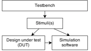
General view of design verification process is presented in Fig. 1. One test bench represents many stimuli as they can be grouped by logical representation of testing context. One or more stimuli activate input signals in Design Under Test (DUT) per clock cycle. All of above are done by running simulation software which in case of this research is ModelSim Student Edition. Simulator also collects valuable verification data such as coverage, generates waveforms, etc.
Figure 1. Concise description of the verification process
Hardware designers then perform extensive simulations for what they call “behavioral verification”, an activity a software engineer might term “validation”, or “software testing”. Because VHDL is similar to a high-level programming language, we can apply software assurance techniques to a hardware design in order to identify and remove faults. These faults need to be detected through the use of test benches. Test bench automation through the generation of test patterns and test cases increases the efficiency and effectiveness of behavioral verification.
Coverage achieved during verification is the single most important parameter for determining the quality
of verification results. In conventional simulation
based verification, coverage of a set of stimuli or testbench measured using various metrics such as code coverage, toggle coverage, FSM coverage [6]. Code coverage measures the fraction of statements in the RTL source code executed or covered while simulating the testbench. Since code coverage can be easily related to the RTL code and reporting it adds little overhead to simulation, it is the most popular coverage metric.
2.1. VHDL Structure
The VHDL description of the device consists of two parts: entity and architecture. The entity
represents the interface of the device, and the architecture is used to code the functional implementation of the device [7]. Different levels of functional implementation can be used. The most frequently used description levels are the following: behavioral, register transfer level (RTL), and structural. The behavioral architecture body of entity describes its function in an abstract way and the concurrent statements in it are limited to process statements, subprogram calls and signal assignments. The process statements are further made up of sequential statements that are much like the kinds of statements we see in a conventional programming language such as statements evaluating expressions, statements assigning values to variables (variable-assignment statements), conditional execution statements (if-then-else, case, etc.), repeated execution statements (loops) and subprogram calls. In addition, there is the signal assignment statement, which is unique to hardware modeling languages. This statement is similar to variable assignment statement, except that it causes the value on a signal to be updated at some future time.
2.2. Finite State Machine
Finite state machine (FSM) is based on quintuple
[8]: N=( 𝑆,Σ, 𝑞0,𝐹,𝛿), where 𝑆 is a finite, non-empty
set of states, Σ – finite, non-empty set of input
symbols, 𝑞0 – initial state 𝑞0𝜖𝑆, 𝐹 – a (possible
empty) set of final states and 𝛿 – transition function
𝛿 ∶ 𝑆×Σ → 𝒫(Σ). Each transition is labeled with a condition that needs to be satisfied for reaching next state.
In VHDL, FSM represents a sequential logic circuit that visits states of some finite set. The process of visiting depends upon the values of the primary inputs and the previous state. The state transitions are synchronized by a clock. Unlike the regular sequential circuit, the state transition of the FSM is more complicated and the sequence exhibits no simple, regular pattern, as in a counter or shift register.
In a synchronous FSM, the transition is controlled by a clock signal (mostly rising) and can occur only at edge of the clock. The main application of an FSM is to implement operations that are performed in a sequence of steps. A large hardware system usually involves complex tasks or algorithms, which can be expressed as a sequence of actions based on system status and external commands. An FSM can function as the control circuit (known as the control path) that coordinates and monitors the operations of other units (known as the data path) of the system.
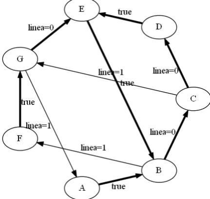
In VHDL, FSMs are mainly represented as if-else or case-when code structures. The difference is in the derivation of the next-state logic, which should be implemented according to a state diagram. The FSM of B02 circuit from ITC99 benchmark suite is presented in Fig. 2.
Figure 2. Graphical representation of FSM in B02
The FSM is characterized by the number of states and the number of transitions. Detailed information on FSM, which was obtained for the benchmarks of ITC’99 suite, is presented in Table 1. Each circuit was evaluated and FSM, states and transitions was counted. The last column in Table 1 named “Paths” represents the total count of elementary circles [10] called paths. We could notice that the benchmark b13 and b15 have four and two processes, respectively. Therefore, the numbers of paths are defined for every process separately. Not necessarily each process must have FSM on its own. It depends on functional requirements and implementation details for each circuit and process. FSM recognition on nested code structures is not supported by the algorithm. Hence, circuits with several processes such as b05, b12 and b14 still need further investigation and advancements in FSM extraction.
2.3. Control flow
In behavioral descriptions of VHDL, the main statement is the process statement. The process statement appears in the implementation part of an architecture statement. The body of the process statement includes sequential statements like those found in software programming languages and it can be implemented as control flow [11]. The architecture can have several processes that operate concurrently but in this research we use only circuits with one process. There is no limitation for the process count.
In our framework, each process is treated as
separate control flow graph 𝐺 = (𝑉,𝐸) . Each
statement in a process is a node 𝑣 ∈ 𝑉 in the control
flow graph and the edges𝑒 ∈ 𝐸 represent the control
flow among statements. We add an edge (𝑒𝑎1,𝑒𝑎2) if
the statement 𝑎1 is executed immediately after the
statement𝑎2.
Our framework supports branch statements (Case, If / Else) of VHDL. For each branch, a node is introduced with edge connection to parent element. A start and an end node will be added as unique entry and exit points of the process. In a control flow graph (Fig. 3), each node represented as a rectangular block matches a straight-line code without any branching. The rectangular blocks can be used to denote either assignment operators or to name the branches of the case operator. The special block with double lines is used to denote the case operator. Directed edges are used to represent jumps in the control flow. Branch operations are shown as diamond.
Table 1. FSM Metrics
Circuit FSM count
FSM states, S
FSM
transitions, δ Paths
b01 1 8 24 24
b02 1 7 10 5
b03 1 3 2 1
b04 1 2 3 1
b05 1 5 8 3
b06 1 7 13 7
b07 1 7 13 4
b08 1 4 9 3
b09 1 4 8 4
b10 1 11 24 10
b11 1 9 38 7
b13 4 8,4,4,10 10,7, 6, 90 3,4,3, 11
b15 2 8, 10 27, 35 17,8
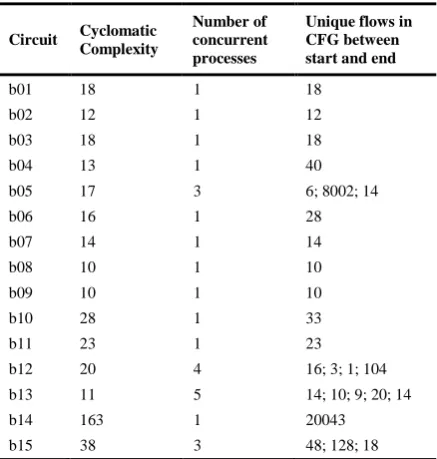
Table 2. CFG Metrics
Circuit Cyclomatic Complexity
Number of concurrent processes
Unique flows in CFG between start and end
b01 18 1 18
b02 12 1 12
b03 18 1 18
b04 13 1 40
b05 17 3 6; 8002; 14
b06 16 1 28
b07 14 1 14
b08 10 1 10
b09 10 1 10
b10 28 1 33
b11 23 1 23
b12 20 4 16; 3; 1; 104 b13 11 5 14; 10; 9; 20; 14
b14 163 1 20043
b15 38 3 48; 128; 18
2.4. Symbolic execution
Symbolic execution (SE) is an extension of normal execution, providing the normal computations as special case. Computational definitions for the basic operators of the language are extended to accept symbolic inputs and produce symbolic formulas as output [13]. The state of a symbolically executed program includes the symbolic values of program variables, a path condition (PC) and a program counter, representing next statement to be executed.
The path condition is a (quantifier-free) BOOLEAN
formula over the symbolic inputs. It accumulates constraints which the inputs must satisfy in order for an execution to follow the particular associated path [14]. A symbolic execution tree characterizes the execution paths followed during the symbolic execution of a program. The nodes represent program
states and the edges represent transitions between states. The main difference between CFG and symbolic execution is that SE produces all possible execution paths of program. Result of symbolic execution is Boolean formula that is solved with SMT solver to provide concrete values.
There are many cases of using SE in software testing and the review paper [15] is already presented, but the use of SE for hardware verification is still in immature state [16, 17]. Andrews et al. [16] present the method RUBASTEM to generate test cases for VHDL behavioral designs. RUBASTEM is based on two tools: a control flow graph generator and a data flow analyzer. Static analysis of VHDL code is used in order to determine the flow of data values through a program.
Liu and Vasudevan [17] present an approach HYBRO to generate input vectors for Verilog RTL designs. HYBRO uses dynamic simulation data and static analysis of Verilog RTL control flow graphs. A concrete simulation is applied over a fixed number of cycles. The corresponding symbolic trace is extracted from the CFG with an RTL symbolic execution engine.
Our approach differs from other known approaches [16, 17] since we used FSM in test generation process. The use of FSM enables to choose the exact number of test cycles to traverse the chosen path in the VHDL code.
3. Framework
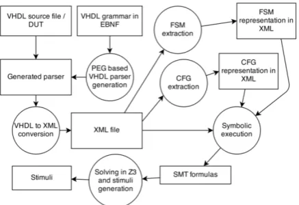
Testbench generation framework “TestBenchGen” combines methods described in previous section into novel methodology. Framework structure is presented in Fig. 4.
All the parts of framework are implemented in Python programming language. Because of complicated structure and development complexity, many Open Source (OS) libraries are used. Grako (for
Figure 4. “TestBenchGen” structure
grammar compiler) is a library that takes grammars in a variation of Extended Backus–Naur Form (EBNF) as input, and outputs memoizing (Packrat) Parsing Expression Grammar (PEG) parsers in Python. Grako is different from other PEG parser generators in that the generated parsers use Python's very efficient exception-handling system to backtrack. Because of complicated nature of VHDL grammar, this feature is very useful to track and fix implementation bugs in parsing phase. For XML handling the cElementTree module is used across many parts in the framework. cElementTree is optimized for fast parsing and low memory use but also has Python backend. That allows rapid prototyping and fast development with quick analysis and traversing of XML files. NetworkX is a Python library for the creation, manipulation and study of the structure, dynamics and functions of complex graph networks. It has a wide variety of standard graph algorithms which are well tested and documented. NetworkX allowed significant decrease in development complexity of graph traversing algorithms. Also NetworkX has a module for exporting and importing GraphViz “dot” format for graph visualizing and visual analysis. Z3 is a high-performance SMT theorem prover being developed at Microsoft Research. It is free for research and academia with public sources. Although written in C/C++, it has Python bindings.
The flow of the algorithm to generate stimuli is
presented in Fig. 5. First, all XML is loaded from prepared files and adequate data structures (mostly directed graphs with weighted edges). In FSM structure, Johnson's algorithm is used to find unique
paths. In the next step, initial state 𝑞0 and next state 𝑞1
of each path in FSM are used as two starting nodes. In between them, all nodes of CFG that correspond to both FSM states are loaded into virtual function. Virtual function is a transformation of VHDL code to Python in such way that binds all local variables,
which exist between 𝑞0 and 𝑞1, to this function
parameters list. Body of virtual function consists of all the programming code that is provided in CFG
between FSM states 𝑞0 and 𝑞1. Virtual function is
executed symbolically and concrete values are
computed by Satisfiability Modulo Theories library Z3 [18]. SMT is an area of automated deduction that studies methods for checking the satisfiability of first-order formulas with respect to some logical theory of
interest. While SMT techniques have been
traditionally used to support deductive software verification, we are using this for calculation of concrete value from SMT formula. That result is used to generate stimuli’s if next state of FSM does not
exist. Otherwise, next states of FSM 𝑞1 and 𝑞2 are
used.
generate_stimuli: read vhdl xml; read fsm xml; read cfg xml;
create graphs from xml; find unique paths in FSM; foreach path in FSM:
if 𝑞𝑎 and 𝑞𝑎+1 in FSM exists: traverse CFG between 𝑞𝑎 and 𝑞𝑎+1; find all local variables;
create virtual function;
execute virtual function symbolically;
traverse symbolic execution tree; find all leaf nodes;
form SMT formula; solve with z3; form stimuli; else:
generate whole stimuli;
Figure 5. “TestBenchGen” test generation algorithm in pseudo code
4. Evaluation
To evaluate the generated test cases, we use three code coverage and two FSM coverage metrics. The code coverage metrics are the following: statement coverage, branch coverage, and focused expression coverage. These metrics are usually used to assess the test cases for software code. To evaluate the hardware specifics, we use the following FSM coverage metrics: state coverage and state transition coverage. The versatility of metrics allows evaluating the generated test cases by various aspects.
Statement coverage measures the number of executable statements within the model that have been executed during the simulation run. In most verification cases, statement coverage is used as minimum goal [19].
Branch coverage [20], sometimes also referred to as decision coverage. This coverage metric measures how many times each branch in an IF or CASE construct was executed and it is particularly useful in situations where a branch does not contain any executable statements.
each input of an expression. If all inputs are fully covered, the expression reaches 100% FEC coverage. In FEC, an input is considered covered only when other inputs are in a state that allows it to control the output of the expression. Further, the output must be observed in both 0 and 1 states while the target input is controlling it. If these conditions occur, the input is said to be fully covered. The final FEC coverage number is the number of fully covered inputs divided by the total number of inputs.
FSM coverage shows the ability to reach all the states and traverse all possible states through a given state machine. Two types of coverage metrics for FSM are used:
State coverage – all states of a FSM are visited during simulation.
State transition coverage – FSM transitions among all states that are achievable during simulation.
In order to evaluate the generated test cases for ITC’99 benchmarks ModelSim Student Edition is used. During this phase the coverage analysis tool inspects the VHDL source code to determine where monitor points should be inserted in order to collect the maximum amount of information about simulation activity in the design.
Currently TestBenchGen was used to generate
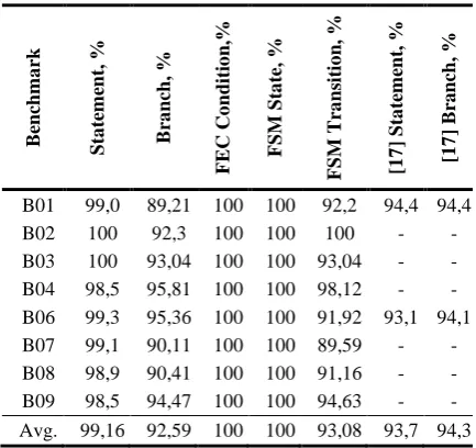
stimuli from B01 to B09 circuits. The detailed view of coverage metrics is presented in Table 3.
In comparison with other quite a new work [17] our method outperforms it for the same ITC’99 benchmark circuits since our method determines the number of test cycles for every path automatically using FSM information. The number of test cycles can be different for different paths. Meanwhile, Liu et al. [17] use the predefined number of test cycles. Besides, Liu et al. make the experiments using the different number of test cycles. We compare B01 and B06 circuits as shown in Table 3. Liu et al. in both cases use 10 cycles. The obtained results indicate the relationship of the number of test cycles to the coverage of test cases.
Table 3. ITC99 detailed results
B en ch m a rk S ta tem en t, % B ra n ch , % F E C Co n d it io n ,% F S M S ta te , % F S M T ra n si ti o n , % [1 7 ] S ta te m en t, % [1 7 ] Br a n ch , %
B01 99,0 89,21 100 100 92,2 94,4 94,4 B02 100 92,3 100 100 100 - - B03 100 93,04 100 100 93,04 - - B04 98,5 95,81 100 100 98,12 - - B06 99,3 95,36 100 100 91,92 93,1 94,1 B07 99,1 90,11 100 100 89,59 - - B08 98,9 90,41 100 100 91,16 - - B09 98,5 94,47 100 100 94,63 - - Avg. 99,16 92,59 100 100 93,08 93,7 94,3
Our presented framework leaves out a need for such experimentation since it determines exactly the needed least number of test cycles for every path separately. Additionally to the increased coverage, the presented framework ensures the lesser number of test cases that is an important advantage, as well.
VHDL processes do not have complex code structures in evaluated ITC’99 circuits. Conditions and logical expressions are not a difficult task for symbolic execution and simulation results show high statement and FEC condition coverage.
During the analysis phase, ModelSim works out the total number of possible branches that could be taken through the VHDL code construct. This value is then compared against the number of branches that were actually taken and the result expressed as a percentage. Branch coverage shows lower results than other metrics. Symbolic execution can fail provide information about some branches that are considered as special cases in hardware verification. For example, all of evaluated ITC’99 circuits have “reset” signal, which requires additional stimuli.
For a design to have a full coverage, it is recommended that the FSM states would be covered fully (100% coverage). This recommendation is satisfied for all the circuits used in the experiment. Our method determines the number of test cycles for every path using FSM states. Therefore, every possible FSM state is analyzed and covered.
5. Conclusions
We presented the framework to generate test cases in order to verify VHDL models. The framework combines techniques used for software and for hardware models since VHDL model is represented at high level and it uses constructs similar to software programs. We combine symbolic execution and control flow graph, which are usually used in the context of software programs, with finite state machine that is attribute of VHDL models. Firstly, the framework explores the FSM of VHDL model in order to define the number of cycles needed to pass from the primary input to primary output. The number of cycles can be different for different paths. Then, when the number of test cycles for the path is determined, the framework solves the problems at the lower level of abstraction using techniques of symbolic execution and CFG for every test cycle separately.
The automated determination of the number of test cycles is an advantage of our framework over the approaches that use predefined number of cycles. This advantage is expressed in two forms: 1) lesser number of test cases; 2) higher coverage of test cases. The reason for this is an adaptable number of test cases to the length of the traversable path in FSM states.
coverage, focused expression coverage, FSM state coverage, and FSM state transition coverage. The first three metrics are usually used to measure quality of the test cases for software code. The last two metrics assess the quality of the FSM coverage. The obtained coverage results using the various metrics indicate high quality of generated test cases.
References
[1] L.-T. Wang, Y.-W. Chang, K.-T. Cheng. Electronic Design Automation: Synthesis, Design and Test.
Morgan Kaufmann Publishers, Burlington, 2009.
[2] U. Legat, A. Biasizzo, F. Novak. On-line self-recovery of embedded multi-processor SOC on FPGA using dynamic partial reconfiguration, Information
Technology and Control, 2012,Vol. 41, No. 2,
116−124.
[3] L. A. Clarke. A system to generate test data and symbolically execute programs. IEEE Transaction on
Software Engineering, 1976, 215–222.
[4] H. Zima, B. Chapman. Supercompilers for Parallel and Vector Computers. ACM Press, New York, NY, 1991.
[5] K. Batcher, C. Papachristou. Instruction Randomization Self Test For Processor Cores. In:
Proceedings of the 17th IEEE VLSI Test Symposium
(VTS’99), San Diego, CA, USA, IEEE Computer
Society, April 25-30,1999, 34-40.
[6] J.-Y. Jou, C. Liu. Coverage analysis techniques for hdl design validation. In: Proc. Asia Pacific CHip
Design Languages, 1999, 48-55
[7] VHDL Standard. Language reference manual, IEEE Std, 1988, pp. 1076-1987.
[8] D. Lee, M. Yannakakis. Principles and methods of testing finite state machines-a survey. In: Proceedings
of the IEEE, 1996,Vol. 84, pp. 1090-1123.
[9] J. Van Lunteren. High-performance pattern-matching for intrusion detection. In: IEEE INFOCOM, 2006. [10] V. Jusas, T. Neverdauskas. FSM Based Functional
Test Generation Framework for VHDL. In: T. Skersys,
R. Butleris, R. Butkiene (eds.), Information and
Software Technologies, Springer Berlin Heidelberg,
2012, Vol. 319, 138-148.
[11] M. Rahmouni, A. A. Jerraya. Formulation and evaluation of scheduling techniques for control flow graphs. In: Design Automation Conference, 1995, with EURO-VHDL, Proceedings EURO-DAC'95.,
European, 1995, pp. 386-391.
[12] G. K. Gill, C. F. Kemerer. Cyclomatic complexity density and software maintenance productivity.
Software Engineering, IEEE Transactions on, 1991,
Vol. 17, 1284-1288
[13] J. C. King. Symbolic execution and program testing.
Commun. ACM, 1976, Vol. 19, 385-394.
[14] S. Khurshid, C. Pasareanu, W. Visser. Generalized Symbolic Execution for Model Checking and Testing.
Lecture Notes in Computer Science, 2003,
Vol. 2619/2003, 553-568.
[15] C. Cadar, P. Godefroid, S. Khurshid, C. S. Păsăreanu, K. Sen, N. Tillmann, W. Visser. Symbolic execution for software testing in practice: preliminary assessment. In: Proceedings of the 33rd
International Conference on Software Engineering,
2011, pp. 1066-1071.
[16] A. Andrews, A. O’Fallon, T. Chen. RUBASTEM: A Method for Testing VHDL Behavioral Models. In:
Proceedings of the Eighth IEEE International
Symposium on High Assurance Systems Engineering
(HASE’04), 25-26 March 2004, 187-196.
[17] L. Liu, S. Vasudevan Efficient validation input generation in rtl by hybridized source code analysis.
In: Design, Automation & Test in Europe Conference
& Exhibition (DATE), 2011, 1596-1601
[18] L. De Moura, N. Bjørner. Z3: An efficient SMT solver. In: Tools and Algorithms for the Construction
and Analysis of Systems, ed: Springer, 2008, 337-340.
[19] I. G. Harris. Fault models and test generation for hardware-software covalidation. Design & Test of
Computers, IEEE, 2003, Vol. 20, 40-47.
[20] S. Tasiran, K. Keutzer. Coverage metrics for functional validation of hardware designs. Design &
Test of Computers, IEEE, 2001, Vol. 18, 36-45.