Volume -2, Issue-4, July – August 2016, Page No. 30 - 36
e
30
ISSN: 2455 - 1597
Implementation of Digital FIR Filter Based on Low power Multiplexer Base Shift/Add Multiplier
1
Shikha Gupta, M.Tech. Global Institute of Technology Jaipur, India 2
Manish Gupta, M.Tech. Shri Bhawani Niketan Institute of Technology & Management Jaipur, India
E-Mail: [email protected]
Abstract
Implementation of a low power and low area digital Finite Impulse Response (FIR) filter. The we method for reduce dynamic power consumption of a digital FIR filter is use of low power multiplexer based on shift/add multiplier without clock pulse and we applied it to fir filter until power consumption reduced thus reduce power consumption due to glitching is also reduced. The minimum power achieved is 56mw in fir filter based on shift/add multiplier in 100MHZ with 8bits inputs and 8-bitscoefficients. The proposed FIR filter was synthesized implemented using Xilinx ISE V7.1 and Virtex IV FPGA to target device xc4vlx200 also power is analyzed using Xilinx X-Power analyzer.
Keywords: Low Power, Shift/Add Multiplier, Barrel Shifter.
1. Introduction
Their impulse response, which can be either finite or infinite. The methods for designing and implementing these two filter classes differ considerably. Finite impulse response (FIR) filters are digital filters whose response to a unit impulse (unit sample function) is finite in duration. This is in contrast to infinite impulse response (IIR) filters whose response to a unit impulse (unit sample function) is infinite in duration..FIR filters are a special kind of digital filters. They are non-recursive type of filter where the present output depends on the present input sample and the previous samples. The impulse response of FIR filter has finite number of non-zero terms. Few characteristics of FIR which serve as their advantage are enlisted below:
• FIR filters have exactly linear phase. • FIR filters are always stable
• FIR filters may be realized in both recursive and Non-recursive structures.
FIR filters with any arbitrary magnitude response can be tackled using FIR sequence. FIR filter scan be implemented using either recursive or non recursive techniques, but usually non recursive techniques are used. FIR filters are widely used in DSP applications. In some applications, the FIR filter circuit must be a low-power circuit operating at moderate sample rates. The low-power or low-area techniques developed specifically for digital filter scan be found in. Parallel (or block) processing can be applied to digital FIR filters to either increase the effective throughput or reduce the power consumption of the original filter. While sequential FIR filter implementation has been given extensive consideration, very little work has been done that deals directly with reducing the hardware complexity or power consumption of parallel FIR filters. Traditionally, the application of parallel processing to an FIR filter involves the replication of the hardware units that exist in the original filter. The topology of the multiplier circuit also affects the resultant power consumption. Choosing multipliers with more hardware breadth rather than depth would not only reduce the delay, but also the total power consumption. A lot of design methods of low power digital FIR filter are proposed, for example, in they present a method implementing fir filters using just registered address and hardwired shifts. They extensively use a modified common sub expression elimination algorithm to reduce the number of adders. In [d] they have proposed a novel approach for assign method of a low power digital baseband processing. Their approach is to optimize the bit width of each filter coefficient. They define the problem to find optimized bit width of each filter coefficient. In presents the method reduces dynamic switching power of a fir filter using data transition power diminution technique (DPDT). This technique is used on adders, booth multipliers. In this research proposes a pipelined variable precision gating scheme to improve the power awareness of the system. This research illustrates this technique is to clock gating to registers in both data flow direction and vertical to data flow direction within the individual pipeline stage based on the input data precision. The rest of the paper is structured as follow. Section2 gives a summary of fir filter theory and inSection3 presents the architecture adopted in our implementation.
2. Fir Filter Theory
Pag
e
31
Pag
e
31
Pag
e
31
Pag
e
31
Pag
e
31
Pag
e
31
Pag
e
31
Pag
e
31
Pag
e
31
Pag
e
31
Pag
e
31
Pag
e
31
Pag
e
31
Pag
e
31
Pag
e
31
Pag
e
31
Pag
e
31
Pag
e
31
Pag
e
31
Pag
e
31
Pag
e
31
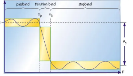
by contrast, operates directly on the analog inputs and is built entirely with analog components, such as resistors, capacitors, and inductors. There are many filter types, but the most common are low pass, high pass, band pass, and band stop. A low pass filter allows only low frequency signals (below some specified cutoff) through to its output, so it can be used to eliminate high frequencies. A low pass filter is handy, in that Low Power FPGA Implementation of Digital FIR Filter Based on Low Power Multiplexer Base Shift/Add Multiplier for limiting the upper most range of frequencies in an audio signal; it's the type of filter that a phone line resembles. A high pass filter does just the opposite, by rejecting only frequency components below some threshold. An example high pass application is cutting out the audible 60Hz AC power "hum", which can be picked up as noise accompanying almost any signal in the U.S. The designer of a cell phone or any other sort of wireless transmitter would typically place an analog band pass filter in its output RF stage, to ensure that only output signals within its narrow, government-authorized range of the frequency spectrum are transmitted. Engineers can use band stop filters, which pass both low and high frequencies, to block a predefined range of frequencies in the middle. Frequency response Simple filters are usually defined by their responses to the individual frequency components that constitute the input signal. There are three different types of responses. A filter's response to different frequencies is characterized as pass band, transition band, or stop band. The pass band response is the filter's effect on frequency components that are passed through (mostly) unchanged. Frequencies within a filter's stop band are, by contrast, highly attenuated. The transition band represents frequencies in the middle, which may receive some attenuation but are not
removed completely from the output signal. In Fig. 1, which shows the frequency response of a low pass filter, ωp is the
pass band ending frequency, ωs is the stop band beginning frequency, and As is the amount of attenuation in the stop
band. Frequencies between ωp and ωs fall within the transition band and are attenuated to some lesser degree.
Figure 1: The response of a low pass filter to various input frequencies.
Given these individual filter parameters, one of numerous filter design software packages can generate the required signal processing equations and coefficients for implementation on a DSP. Before we can talk about specific implementations, however, some additional terms need to be introduced. Ripple is usually specified as a peak-to-peak level in decibels. It describes how little or how much the filter's amplitude varies within a band. Smaller amounts of ripple represent more consistent response and are generally preferable. Transition bandwidth describes how quickly a filter transitions from a pass band to a stop band, or vice versa. The more rapid this transition, the higher the transition bandwidth; and the more difficult the filter is to achieve. Though an almost instantaneous transition to full attenuation is typically desired, real-world filters don't often have such ideal frequency response curves. There is, however, a tradeoff between ripple and transition bandwidth, so that decreasing either will only serves to increase the other. Digital filters are typically used to modify or alter the attributes of a signal in the time or frequency domain. The most common digital filter is the linear time-invariant (LTI) filter. An LTI interacts with its input signal through a process called linear convolution, denoted by y = h.x where h is the filter‟s impulse response, x is the input signal, and y is the convolved output. The linear convolution process is formally defined by:
y[n] = x[n]h[n] =Σ x[n]h[n-k]=Σ h[k]x[n-k]……... (1)
k=0 k=0
An FIR with constant coefficients is an LTI digital filter. The output of an FIR of order or length L, to an input time-series x[n], is given by a finite version of the convolution sum given in (1), namely:
L-1 y[n]=x[n]×h[n]=Σ h[k]x[n-k]…………(2)
k=0
Where h[0] ≠ 0 through h[L − 1] ≠ 0 are the filter’s L coefficients.
e
32
e
32
e32
e
32
e32
e
32
e32
e
32
e32
e
32
e
32
e
32
e
32
e32
e
32
e32
e
32
e32
e
32
e32
e
32
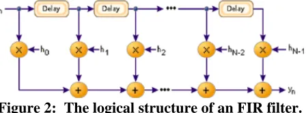
The hk values are the coefficients used for multiplication, so that the output at time n is the summation of all the delayed samples multiplied by the appropriate coefficients.
Figure 2: The logical structure of an FIR filter.
The process of selecting the filter's length and coefficients is called filter design. The goal is to set those parameters such that certain desired stop band and pass band parameters will result from running the filter. Most engineers utilize a program such as MATLAB to do their filter design. But whatever tool is used, the results of the design effort should be the same:
1) A frequency response plot, like the one shown in Fig.1, which verifies that the filter meets the desired specifications, including ripple and transition bandwidth.
2) The filter's length and coefficients.
3. Implementation
The implementation has been explained below starting with calculation of coefficients using MATLAB, followed by VHDL program and its implementation:
First Coefficient calculation in MATLAB the Remez FIR Filter Design block implements the Parks-McClellan algorithm to design and apply a linear-phase filter with an arbitrary multiband magnitude response. The filter design, which uses the firpm function in Signal Processing Toolbox, minimizes the maximum error between the desired frequency response and the actual frequency response. Such filters are called equiripple due to the equiripple behavior of their approximation error. The block applies the filter to a discrete-time input using the Direct-Form II Transpose Filter block. An M-by-N sample-based matrix input is treated as M*N independent channels and an M-by-N Frame-based matrix input is treated as N independent channels. In both cases, the block filters each channel independently over time, and the output has the same size and frame status as the input.
The Filter type parameter allows you to specify one of the following filters:
• Multiband: The multiband filter has an arbitrary magnitude response and linear phase.
• Differentiator: The differentiator filter approximates the ideal differentiator. Differentiators are anti symmetric FIR filters with approximately linear magnitude responses. To obtain the correct derivative, scale the Gains at these frequencies vector by pFs rad/s, where Fs is the sample frequency in Hertz.
• Hilbert Transformer:
The Hilbert transformer filter approximates the ideal Hilbert transformer. Hilbert transformers are anti symmetric FIR filters with approximately constant magnitude.
Parks-McClellan optimal FIR filter design Syntax
b = firpm(n,f,a) b = firpm(n,f,a,w)
Firpm designs a linear-phase FIR filter using the Parks-McClellan algorithm. The Parks-McClellan algorithm uses the Remez exchange algorithm and Chebyshev approximation theory to design filters with an optimal fit between the desired and actual frequency responses. The filters are optimal in the sense that the maximum error between the desired frequency response and the actual frequency response is minimized. Firpm exhibits discontinuities at the head and tail of its impulse response due to this equiripple nature. b = firpm(n,f,a) returns row vector b containing the n+1 coefficients of the order n FIR filter whose frequency-amplitude characteristics match those given by vectors f and a. The output filter coefficients (taps) in b obey the symmetry relation:
Vectors f and a specify the frequency-magnitude characteristics of the filter:
• f is a vector of pairs of normalized frequency points, specified in the range between 0 and1, where 1 corresponds to the Nyquist frequency. The frequencies must be in increasing order.
Pag
e
33
Pag
e
33
Pag
e
33
Pag
e
33
Pag
e
33
Pag
e
33
Pag
e
33
Pag
e
33
Pag
e
33
Pag
e
33
Pag
e
33
Pag
e
33
Pag
e
33
Pag
e
33
Pag
e
33
Pag
e
33
Pag
e
33
Pag
e
33
Pag
e
33
Pag
e
33
Pag
e
33
The desired amplitude at frequencies between pairs of points (f(k), f(k+1)) for k odd is the line segment connecting the points (f(k), a(k)) and (f(k+1), a(k+1)).The desired amplitude at frequencies between pairs of points (f(k), f(k+1)) for k even is unspecified. The f are as between such points are transition or "don't care" regions.
• f and a must be the same length. The length must be an even number.
4. Filter Specification
The implementation of Remez fir filter is done for the specifications characterizing an equiripple fir design method for a band pass response type. The frequency specifications are as follows:
• SAMPLING FREQUENCY,FS =48000HZ • STOP BAND FREQUENCY1.FSOTP1=7200HZ • Pass band Frequency1, Fpass1 = 9600 Hz • Pass band Frequency2, Fpass2 = 12000 Hz • Stop band Frequency2. Fsotp2 = 14400 Hz
Figure 3 (a): Magnitude Response of Remez FIR filter of order 20
Figure 3 (B): Magnitude Response of Remez FIR filter of order 40 With additional discussion:
VHDL Code
e
34
e
34
e34
e
34
e34
e
34
e34
e
34
e34
e
34
e
34
e
34
e
34
e34
e
34
e34
e
34
e34
e
34
e34
e
34
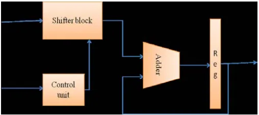
Figure 4: Block diagram of low power multiplexer based shift/add multiplier.
The following is the VHDL code for the above filter depicting the Optimal Linear Filter using
5. The Remez Exchange Algorithm: library IEEE
use ieee.std_logic_1164.all;
use ieee.std_logic_arith.all;
use ieee.std_logic_unsigned.all;
entity sas_fir is
generic (n: integer:=4;
m: integer:=8);
port(x:in std_logic_vector(m-1 downto 0);
clk,rst : in std_logic;
z : out std_logic_vector(2*m-5 downto 0));
end sas_fir;
architecture unsignd of sas_fir is---- declaration of array for storing registers and coefficient values type shft_reg is array (n-2 downto 0) of std_logic_vector(m-1 downto 0);
type coefficients is array (n-1 downto 0) of std_logic_vector(m-1 downto 0);
signal reg_shft: shft_reg;
signal count: std_logic_vector(21 downto 0);
signal clk1: std_logic;
signal i: std_logic_vector(7 downto 0);
signal y : std_logic_vector(2*m-1 downto 0);
storing coefficeint values as constant
constant w : std_logic_vector(0 to 2*m -1) := "0000000000010000";
Pag
e
35
Pag
e
35
Pag
e
35
Pag
e
35
Pag
e
35
Pag
e
35
Pag
e
35
Pag
e
35
Pag
e
35
Pag
e
35
Pag
e
35
Pag
e
35
Pag
e
35
Pag
e
35
Pag
e
35
Pag
e
35
Pag
e
35
Pag
e
35
Pag
e
35
Pag
e
35
Pag
e
35
begin
process(rst, clk,count)
begin
---task to be peformed at reset=1---
if( rst='1') then
for i in n-2 down to 0 loop
for j in m-1 down to 0 loop reg_shft(i)(j)<='0';
end loop; --- end of loop in j
end loop; --- end of loop in i
---task to be peformed at reset=0---elsif(clk1'event and clk1='1') then
sum:= coeff(0) * x;
for i in 1 to n-1 loop
o_mul:= coeff(i) * reg_shft(n-1-i);
sum:= sum + o_mul;
end loop; --- end of loop in i
reg_shft <= x & reg_shft(n-2 downto 1);
end if;
y <= sum; ---- sum of all the o_mul's is send as output
for i in 0 to 2*m-5 loop
z(i) <= y(i+4);
end loop;
end process; --- end of process
end unsignd;
6. Conclusions
The result of the now constructed VHDL code can has been verified on an FPGA (Field Programmable Gate Arrays). Resources of FPGA used have been listed below:
No. of Slices : 57 out of 2352
e
36
e
36
e36
e
36
e36
e
36
e36
e
36
e36
e
36
e
36
e
36
e
36
e36
e
36
e36
e
36
e36
e
36
e36
e
36
No. of 4-input LUTs : 96 out of 4704
No. of bonded IOBs : 22 out of 140
No. of GCLKs : 02 out of 4
A Generic FIR filter using Remez Exchange Algorithm has been implemented on AFP GA. The coefficients were obtained using the Filter Design and Analysis Tool of MATLAB. The implementation in HDL offers the possibility to generate and use the FIR filter in any developing environment. The implementation of FIR filter using Remez Exchange Algorithm finds most of its applications, particularly in industry. The FIR filter using Remez Exchange Algorithm is optimal in the sense that it minimizes the maximum error between the desired frequency response and actual frequency response. Hence, it is also called MINIMAX filter. Implementation is also found to be very much user-friendly. Besides this it gives a very universal approach to the field of signal processing. The use of Remez Exchange algorithm includes several advantages over other methods of calculating filter coefficients. This particular algorithm tremendously reduces the number of multipliers and adders being used in narrow-transition band linear-phase FIR filter. The overall process of synthesis is found to be very much faster than other methods known. It is a powerful technique for designing arbitrary magnitude linear-phase FIR filter. Also A low power and low area FIR filter. For reduce power consumption and area we using of shift/add multiplexer based multiplier. This filter was compared for area and power with other common implementations and it demonstrated that our approach is most effective for implementations with the constraints of low cost and low power.
7. References
[1] K. Tarumi, A. Hyodo, M. Muroyama, and H. Yasuura, “A designmethod for a low power digital FIR_lter indigital wirelesscommunication systems,” 2004.
[2] A. F. Shalash and K. K. Parhi, “Power efficient folding of pipelinedLMS adaptive filters with applications,” Journal of
VLSI Signal Processing, pp. 199-213, 2000.
[3] S. Mirzaei, A. Hosangadi, and R. Kastner, “FPGA implementation of high speed fir filters using add and shift method,” IEEE, 2006.
[4] H. J. G. Chung and K. K. Parhi, “Frequency spectrum based low-area low-power parallel fir filter design,” EURASIP
Journal on Applied Signal Processing 2002, vol. 31, pp. 944-953.