Development of Electrospun Iminochitosan for
Improved Wound Healing Application
Rupesh Gajanan Nawalakhe, M.S.1, Samuel M. Hudson, Ph.D.1, Abdel-Fattah Mohamed Seyam, Ph.D.1 Ahmed I. Waly, Ph.D.2, Nabil Y. Abou-Zeid, Ph.D.2, Hassan M. Ibrahim, MS2
1
North Carolina State University, Raleigh, North Carolina UNITED STATES
2
National Research Center, Cairo, EGYPT
Correspondence to:
Rupesh Gajanan Nawalakhe email: [email protected]
ABSTRACT
Chitosan is a well known anti-microbial polymer. It is desired to develop and evaluate chitosan based structures with high surface area using electrospun nanofibers. To explore the properties of chitosan derivatives, iminochitosan was synthesized and electrospinning of its solutions was conducted. Nanofibers were obtained from iminochitosan solutions using trifluoroacetic acid (TFA) as a solvent. Nanofiberwebs of fiber diameter range 70-400 nm were successfully obtained from 3%-8% iminochitosan solution in TFA using electrospinning technique of electric field of 2.5-6.0 kV/cm. Contact kill performance of the iminochitosan structures against a range of microbes was carried out using the disc diffusion method. The results indicate that the nanofiberwebs exhibit excellent antimicrobial behavior. It was found that the inhibition zone is affected by the iminochitosan structure parameters, namely covering power, surface area (which was affected by diameter), and basis weight. Viscosity of the solutions was determined and fiber formation was obtained in the range of 400-670cP.
Keywords: Chitosan; iminochitosan; salicylaldehyde; electrospinning; antimicrobial
INTRODUCTION
Nanofiber formation using an electrospinning technique is a very effective method for obtaining high surface area fibrous mats. The nanofibers provide a very large surface area due to their extreme small size, which makes them suitable to form filtration products, and particularly for medical textile products such as surgical facemasks, wound dressings, and drug delivery systems [1]. A biopolymer of interest for such applications as these is chitosan. Its bioactivity and general properties are well known [2-5].
Through electrospinning, biocompatible polymers can be spun into a nano-sized mesh. This nanomesh is composed of fibers with a high surface area, and a nano-sized diameter that can be used to mimic a natural extra-cellular matrix, which acts as scaffolding that allows cells to attach, proliferate, differentiate, and develop essential functions within tissue [6-9]. Providing cells with an artificial extra-cellular matrix encourages tissue growth and therefore promotes healing. Using chitosan as a component in the extra-cellular matrix would also promote healing due to the chitosan’s unique biological properties. Chitosan is biodegradable, biocompatible, nontoxic, a haemostatic, and a natural antibacterial agent [10-15].
Antibacterial behavior of chitosan is explained by the interaction of the positively charged chitosan with the negatively charged residues at the cell surface of microbes, which causes extensive cell surface alterations and alters cell permeability [16-22]. This causes the leakage of intracellular substances, such as electrolytes, UV- absorbing material, proteins, amino acids, glucose, and lactate dehydrogenase inhibiting the normal metabolism of microorganisms and finally leads to the death of these cells.
onto glass plates [28]. Xinying Geng et al reported that chitosan nanofibers can be obtained by dissolving chitosan in acetic acid [29]. In [28, 29], the authors did not report antibacterial evaluation of the films and fibers. It is expected that cellulose-chitosan blend films (or fibers) may reduce or inhibit the antimicrobial behavior of the chitosan depending on which polymer dominates the surface. Due to its polyelectrolyte nature chitosan is not easily electrospun [30]. For this reason, researchers electrospun chitosan either using core/sheath technique mixed chitosan with other polymer in the spinning solution.
Gorga and Ojha [31] were able to electrospin chitosan nanofibers using core/sheath geometry with polyethylene oxide (PEO) as sheath and chitosan in the core. However, this technique requires dissolving the PEO to obtain chitosan nanofiberweb. Bhattarai et al were able to form nanofibers from solutions containing chitosan, polyethylene oxide, and Triton X-100TM [32]. However, Ohkawa et al were able to form pure chitosan nanofibers using TFA as solvent. They reported a linear relationship between concentration of chitosan in TFA and diameter of chitosan nanofibers [33, 34].
In this work, we report the electrospinning of a chitosan derivative (iminochitosan) that is formed by the Schiff base reaction between salicylaldehyde and chitosan [35]. This derivative is not a polyelectrolyte and chitosan is easily regenerated by hydrolysis if so desired. The iminochitosan nanofibers were directly deposited on cotton gauze and the antimicrobial properties were determined.
It was thought that it might be necessary to regenerate the chitosan from iminochitosan electrospun nanofibers to obtain antimicrobial properties. This can be done by treating iminochitosan with dilute acetic acid. In fact, iminochitosan releases salicylaldehyde due to hydrolysis when in contact with moisture from the atmosphere or wound. It is reported that salicylaldehyde possesses antimicrobial property itself [36]. Therefore, the development of electrospun fiberwebs from iminochitosan solution is a justified route without the need for an additional process that converts it back to chitosan. Additionally, iminochitosan is expected to provide better antimicrobial characteristics compared to chitosan.
EXPERIMENTAL Synthesis of Iminochitosan
Iminochitosan was selected as a candidate for electrospinning trials. Iminochitosan was prepared to cover the free amino groups and prevent polyelectrolyte formation [33]. It was prepared by the reaction of chitosan (100 g) with salicylaldehyde (130 ml) in 1.5 liter of water at room temperature for 6 hours. The modified chitosan was filtered and washed with distilled water several times. Methanol extraction was done in soxhlet for 6 hours. The product was dried at room temperature for 24 hours to obtain the final iminochitosan.
Preparation of Electrospinning Solutions From Iminochitosan
A flask containing the iminochitosan and TFA was placed in acetone/dry ice bath and frozen. It was then thawed in a water bath at ambient temperature. The iminochitosan dissolved in the TFA very quickly as a result of the sudden freezing and thawing. The solution was left overnight. After that the solution was ready to be electrospun.
Electrospinning Equipment
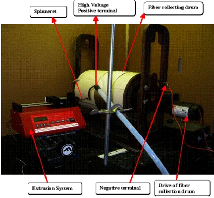
The electrospinning equipment used consists of an extrusion system (syringe pump), fiber collection system, and high voltage supply Figure 1. The
FIGURE 1. Electrospinning equipment.
Voltage, Inc., Model Number PS/WK125RS.0J48, Input: 115VA, 48-63Hz. 1PH, Output: +/- 125 kV DC, 5 mA). The terminal wire (positive electrode) from the high voltage power supply was fixed to the extrusion needle (1 mm inner diameter).
The fiber collection system Figure 1 includes a drum of 22 cm diameter and 35.6 cm long that is made of polyvinyl chloride (PVC). The drum is fixed to an electrically isolated wooden frame and connected to a motor and speed controller. The drum and the frame are made from non-electrically conductive material to eliminate fiber deposition on unwanted areas. A brass ring is attached to one side of the drum. The ring is in contact with a brass bush, which in turn is connected to the negative electrode of the high voltage power supply. A brass rod is placed on a groove in the drum throughout its length and fixed at one end by the brass ring. The brass rod carries the electric field given by the brass ring. An aluminum (or any conductive material) foil is wound over the drum and passes under the brass rod. This is done to maintain the same electric field over the area covered by the conductive foil.
In all electrospinning trials, a strip of 10-cm wide aluminum foil was mounted securely around the fiber collecting drum Figure 1. Gauze of the same width was mounted over the aluminum foil. Part of the aluminum foil was not covered by gauze. By rotating the drum at low speed (1-3 m/min), an iminochitosan nanofiber layer was spun over the gauze and the aluminum foil without any difficulty since the gauze structure is very open and allowed the electrical field to form nanofibers. Samples from the nanofiberweb with aluminum foil were taken for SEM imaging and samples from nanofiberwebs /gauze were taken for antimicrobial evaluation.
Antimicrobial Evaluation
The disc diffusion method (ASTM E2149-01) was used for assessing the iminochitosan nanofiberwebs for antimicrobial activity. Discs of 7 mm diameter were cut from the composite structure of gauze and iminochitosan layer. Nutrient agar plates were incubated with microbial culture. The cut discs of gauze/iminochitosan structures were placed onto the surface of inoculated plates. The plates were incubated at 37oC for 48 hours. The inhibition zone (distance from disc in mm) was determined for each disc. Four bacterial cultures were used for assessing the antimicrobial activity of prepared samples. These microorganisms were obtained from the culture collection of the Microbiology Departments, Women’s College for Arts, Science and Education,
Ain Shames University, Cairo, Egypt. Table I shows the microorganisms cultured for the purpose of evaluating the antimicrobial behavior of the samples.
TABLE I. Microorganisms used for the antimicrobial investigation.
Characterization
Viscosity plays an important role in extrusion of the solution through the needle and decides fiber diameter and morphology. Viscosity of the solution at different concentration was measured with a Brookfield viscometer. Viscosity measurement was carried out at room temperature of 25° C. The covering power of the nanofiberweb was determined by using MATLAB® computer software. First, the fiberweb images were converted from RGB (red, green, blue) to grayscale and the level of black and white was set using the Graythrash function. The white color was assigned to the fibers and the black color to the background. The ‘Area’ function was used to calculate the fiber covering power, which is the percentage area covered by the fibers (or by white color).
RESULTS AND DISCUSSION
spinneret occurred and it was not possible to spin enough material for further testing and evaluation. A more powerful extrusion pump may solve the issue of clogging. For this reason concentration in the range of 1%-5% were used for the main experiment.
FIGURE 2. SEM image of nanofiberwebs produced at 8% polymer concentration.
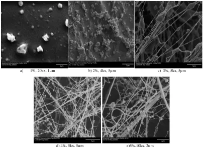
Electrospinning trials were conducted from these solutions and the corresponding SEM images are shown in Figure 3.
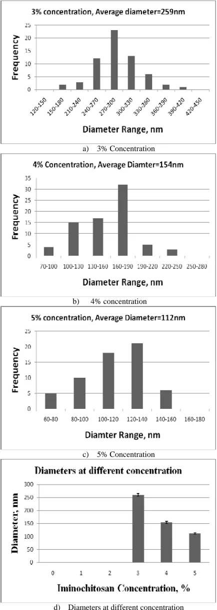
Figure 3 shows that at low concentration (1% and 2 %) beads and films were formed. At such low concentrations, the solutions do not have sufficient viscosity to produce solid continuous fibers. With increasing polymer concentration, the number of direct interchain associations of iminochitosan molecules in the solution increases. As the concentration was increased to 3% and 4 % continuous fibers were formed. For 3% concentration, nanofibers with diameter of 150 to 390 nanometers range (approx.) were found whereas for the 4 % concentration, the range is 70 to 250 nanometers (approx.) and for 5% concentration ranging from 70-160 nanometers. Figure 4 shows diameter distribution of nanofibers at 3%- 5% concentrations. It was observed that as solution concentration increased diameter decreased. This behavior between nanofiber diameter and concentration is because iminochitosan acts as a partial polyelectrolyte and increases the conductivity of the polymer solution, thereby decreasing the diameter of the nanofibers [37, 38]. Another reason for decrease in the diameter with increase in concentration can be observed because of partial clogging or restriction to flow at the tip of needle [39]. This clogging of needle can be attributed to higher viscosity of the solution of iminochitosan in TFA.
a) 1%, 20kx, 1µm b) 2%, 4kx, 5µm c) 3%, 5kx, 5µm
d) 4%, 5kx, 5µm e)5%,10kx, 2µm
a) 3% Concentration
b) 4% concentration
c) 5% Concentration
d) Diameters at different concentration
FIGURE 4. Diameter distribution of iminochitosan nanofibers at different concentration of polymer solutions.
Table II shows the details of the parameters used for the electrospinning trials. During electrospinning of iminochitosan at 3% and 4% concentrations it was observed that the solution directly deposited on the collection surface resulted in fusion of the fibers. In order to reduce this fusion, the distance between the spinneret and collection surface (drum) was increased from 5 cm to 8 cm. The reduction in the field allowed the solvent enough time to evaporate. Another way to reduce the fiber fusion is to reduce the extrusion rates of solution in order to decrease the time for the solvent to evaporate.
TABLE II. Parameters of electrospinning trials.
Concentration, %
Potential, V
Distance, cm
Field, V/cm
1 30 8 3.75
2 30 8 3.75
3 30 5-8 3.75-6.00
4 30 5-8 3.75-6.00
5 30 8-10 3.00-3.75
8 25 10 2.50
As it can be seen from Figure 5, as the concentration of iminochitosan in TFA increases, the viscosity of the solution increases. In short, viscosity of the solution is directly proportional to the iminochitosan solution concentration. This results in higher fiber forming tendency at higher viscosity. This leads to more intermolecular entanglements which lead to
FIGURE 5. Relationship between iminochitosan concentration and viscosity.
better fiber formation. During initial trials of electrospinning using solution of 1% and 2% concentration there was not sufficient amount of polymer to form the fibers that resulted in formation of beads and films. Therefore the best solution viscosity of solution of iminochitosan in TFA was found to be in range of 400-670 cP which corresponds to a 3%-5% concentration range of iminochitosan. Images of nanofibers are as shown in
TABLE III. Antimicrobial Assessment Results.
Effect of Electrospun Fiberweb Structure on Antimicrobial Behavior
Table III shows inhibition zone results for different microorganism cultured on discs of gauze layer without iminochitosan layer (control sample) and gauze/iminochitosan composite structures with iminochitosan nanofiberwebs (or beads/films). The % concentration is the iminochitosan concentration in solution with TFA as indicated earlier. It can be seen from Table III that the control sample provided no antimicrobial protection within or beyond the disc (sample area). Due to their low surface area, structures spun from 1% and 2% solution provided poor antimicrobial performance. These structures are characterized by beads and partial films. The samples containing iminochitosan layer that were spun from solution concentration of 3%-5% were very effective in contact killing of the microorganisms, as indicated by the large inhibition zone. The antimicrobial effectiveness of the material increased with the % concentration of the iminochitosan.
During electrospinning, same volume of solution was used to form each nanofiberweb. Therefore, the basis weight (mass/area) covered by the nanofiberwebs increased with concentration, which led to an increase of the inhibition zone with concentration.
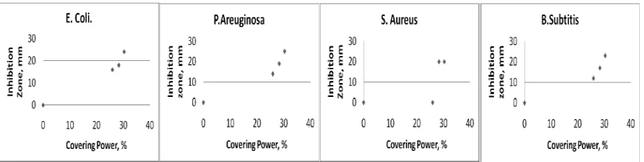
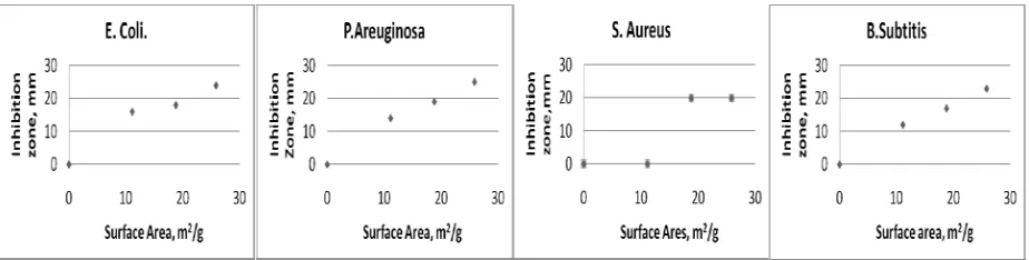
Figure 6 and 7 show the graphical presentation of the contact kill of the four microorganisms (presented by the inhibition zone in mm) as a function of covering power and surface area which is affected by basis weight and fiber diameter. Covering power is the optical area (area projected on plane parallel to fiberweb plane) covered by the iminochitosan nanofibers on the wound dressing. The results indicate that the inhibition zone increases with increase in covering power and surface area. As covering power of the fibers increases, the area covered by the iminochitosan also increases Figure 6. This results in higher antimicrobial efficiency and thus increases the wound healing performance.
FIGURE 7. Effect of surface area on inhibition zone.
The smaller the diameter, the higher is the surface area of the fibers and the higher is the inhibition zone. Figure 7 shows effect of surface area on the inhibition zone. In this graph, the effect of basis weight and the fiber diameter was combined. Basis weight was increased by increasing the concentration and keeping the volume of extruded solution constant. Absence of data-points in the graph was due to formation of beads and partial films at 1% and 2% concentration. These data points were excluded from
Figure 6 and 7. In Figure 6 and 7; the graphs indicating S. Aureus with covering power of 26.0% and a surface area of 11.1 m2/g showed no inhibition zone due to variability and random selection of the sample and the sample is believed to have very small amount of nanofibers.
Inherent antibacterial property of iminochitosan can be explained by positively charged iminochitosan interacts with the negatively charged residues as discussed in introduction section causing the leakage of intracellular substances [16-22]. As a result, iminochitosan inhibits the normal metabolism of microorganisms causing the death of these cells. In addition to cationic effect, antibacterial behavior of iminochitosan is attributed to the release of the salicylaldehyde by hydrolysis which act as antibacterial [36]. The effect of charge and salicylaldehyde would increase with the increase in surface area, basis weight and covering power.
CONCLUSION
Our research revealed the correct blend of solution and electrospinning parameters that led to the formation of electrospun nanofiberwebs from iminochitosan without the need to blend with other polymers or using additional steps. Several parameters including polymer concentration, electric field and extrusion rate were investigated in the electrospinning of iminochitosan dissolved in TFA. The trials showed that good fiber formation occurred within a range of 3%-8% of iminochitosan concentration with viscosity in the range of 400-670
cP respectively. Concentration below 3% produced beads and films and concentrations higher than 8% were not possible to extrude with the extruder system employed. The electrospinning concentrations in the range of 1%-5% were studied for antibacterial testing since 8% concentration solution created a problem of frequently blocking the needle. We conclude that the electrospinning of iminochitosan is possible with the use of TFA as a solvent. Moreover it produced fibers with barbed structures so as to increase the fiber surface area. Contact kill performance of the gauze/iminochitosan structures against range of microbes showed an excellent antimicrobial behavior. Iminochitosan structure parameters namely covering power, basis weight, and fiber diameter that are determining the surface area of the structure are strongly correlated to the inhibition zone. The increase in surface area (increase in basis weight and covering power and reduction in fiber diameter) led to higher antimicrobial effectiveness of the structure as presented by the inhibition zone.
ACKNOWLEDGEMENT
We extend our appreciation for the financial support from the National Science Foundation of USA (Award Number 0709654), the Academy of Scientific Research of Egypt, and North Carolina State University.
REFERENCES
[1] Jayaraman, K., Kotaki, M., Zhang, Y., Mo., Xiu, M., and Ramakrishna, S., (2004), Recent Advances in Polymer Nanofibers, Journal of Nanoscience and Nanotechnology, Vol. 4, No. 1-2, pp. 52-65.
[3] Hudson, S.M., Lim, S., (2003), Review of Chitosan and Its Derivatives as Antimicrobial Agents and Their Uses as Textile Chemicals, J. of Macromol. Sci., Reviews, Vol. 43 No. 2, PP. 223-269.
[4] Hudson, S.M., Ravi Kumar, M.N.V., (2004), Chitosan, in Encylcopedia of Biomaterials and Biomedical Engineering, Dekker Pub., New York.
[5] Whang, H.S., Kirsch, W., Zhu, Y. H., Yang, Cheng Z., Hudson, S. M. (2005), Hemostatic agents derived from chitin and chitosan. Journal of Macromolecular Science, Polymer Reviews, Vol. 45, No. 4, PP. 309-323. [6] Schindler, M., Ahmed, I., Kamal, J.,
Nur-E-Kamal, A., Grafe, T. H., Chung, H. Y. and Meiners S., (2005), A synthetic nanofibrillar matrix promotes in vivo-like organization and morphogenesis for cells in culture. Biomaterials Vol. 26 No. 28, PP. 5624-5631. [7] Ma, Z. W., Kotaki, M., Inai, R., and
Ramakrishna, S., (2005), Potential of nanofiber matrix as tissue-engineering scaffolds, Tissue Engineering Vol.11, No. 1-2, PP. 101-109.
[8] Dvir, T., Gang, T., and Cohen, S., (2005), Designer Scaffolds for Tissue Engineering and Regeneration, Israel Journal of Chemistry Vol. 45, pp. 487-494.
[9] Venugopal, J. and Ramakrishna, S., (2005), Applications of polymer nanofibers in biomedicine and biotechnology. Applied Biochemistry and Biotechnology pp.147-157. [10] Hudson, S.M., and Jenkins, D. W., (2001),
Chitin and Chitosan. Encyclopedia of Polymer Science and Technology, Published online in Wiley Interscience.
[11] Ueno, H., Mori, T., and Fujinaga, T., (2001), Topical Formulations and Wound Healing Applications of Chitosan. Advanced Drug Delivery Reviews, pp. 105-115.
[12] Martino, D., Alberto, Sittinger, M., and Makarand, V., (2005), Chitosan: A Versatile Biopolymer for Orthopaedic Tissue-engineering. Biomaterials Vol. 26 pp. 5983-5990.
[13] Li, Q., Grandmaison, E. W., Goosen, M. F. A., and Dunn, E. T., (1992), Applications and Properties of Chitosan. Journal Of Bioactive And Compatible Polymers Vol. 7, No. 4, pp. 370-397.
[14] Khor, E. and. Lim, L. Y., (2003), Implantable applications of chitin and chitosan, Biomaterials, Vol. 24, No. 13, pp. 2339-2349.
[15] Senel, S. and McClure, S. J., (2004), Potential applications of chitosan in veterinary medicine. Advanced Drug Delivery Reviews Vol. 56. No.10, pp. 1467-1480.
[16] Sudardshan, N.R., Hoover, D.G., and Knorr, D., (1992), Antibacterial action of chitosan, Food Biotechnol., Vol. 6, No. 3, pp. 257-272. [17] Fang, S.W., Li, C.F., and Shih, D.Y.C., (1994).,
Antifungal activity of chitosan and its preservative effect on low-sugar candied kumquat, J. Food Protect., Vol. 56, No. 2, pp. 136-140.
[18] Hwang, J.K., Kim, H.J., Yoon, S.J., and Pyun, Y.R. (1998), Bactericidal activity of chitosan on E. coli, in Advances in Chitin Science, Vol. III (R. H. Chen and H. C. Chen, Eds), Rita Advertising Co. Ltd., Taiwan, pp. 340-344.
[19] Tsai, G.J. and Su, W.H. (1999), Antibacterial activity of shrimp chitosan against Escherichia coli, J. Food Protect., Vol. 62, No. 3, pp. 239-243.
[20] Helander, I.M., Nurmiaho-Lassila, E.L., Ahvenainen, R., Rhoades, J., and Roller, S., (2001), Chitosan disrupts the barrier properties of the outer membrane of gram-negative bacteria, Int. J. Food Microbiol., Vol. 71, pp. 235-244.
[21] Young, D.H., Köhle, H., and Kauss, H., (1982), Effect of chitosan on membrane permeability of suspension-cultured Glycine max and Phaseolus vulgaris cells, Plant Physiol., Vol. 70, pp.1449-1454.
[22] Young, D.H. and Kauss, H., (1983)., Release of calcium from suspension-cultured Glycine max cells by chitosan, other polycations, and polyamines in relation to effects on membrane permeability, Plant Physiol., Vol. 73, pp. 698-702.
[23] Qin, Y., (1994), Chitin and Chitosan as Wound Dressing Materials, Textile Horizons Vol. 14, No. 6, pp. 19-21.
[24] Ueno, Mori, H. and Fujinaga, T., (2001), Topical Formulations and Wound Healing Applications of Chitosan, Advanced Drug Delivery Reviews, pp.105-115.
[25] Raymond, L., Morin, F.G., Marchessault, R.H., (1993), Degree of deacetylation of chitosan using conductometric titration and solid-state NMR, Carbohyd. Res., Vol. 246, pp. 331-336.
[27] Wu, Y.B., Yu, S.H., Mi, F.L., Wu, C.W., Shyu, S.S., Peng, C.K., and Chao, A.C., (2004), Preparation and Characterization on Mechanical and Antibacterial Properties of Chitosan/Cellulose blends, Carbohydrate Polymers, Vol. 57, No. 4, pp. 435-440.
[28] Hasegawa, M., Isogai, A., Kuga, S., and Onabe, F., (1994), Preparation of Cellulose-Chitosan
Blend Film Using Chloral/Dimethylformamide, Polymer, Vol.
35, No. 5, pp. 983-987.
[29] Geng, X., Kwon, o., Jang, J.,(2005), Electrospinning of chitosan dissolved in concentrated acetic acid solution, Biomaterials, Vol. 26, pp. 5427–5432
[30] Nawalakhe, R., Seyam, A., Hudson, S., (2009), Master’s Thesis, Improving healing performance of wound dressing: electrospinning of chitosan-based, cellulose-based fibers and their blends, NCSU.
[31] Ojha, S., Gorga, R., (2008), “Fabrication and Characterization of Electrospun Chitosan Nanofibers Formed via Templating with Polyethylene Oxide” Biomacromolecules, Vol.9, pp. 2523–2529.
[32] Bhattarai, N., Edmondson, D., Veishe, O., Matsen, F.A.., and Zhang, M., (2005), Electrospun Chitosan-Based Nanofibers and Their Cellular Compatibility, Biomaterials, Vol. 26, No. 31, pp. 6176-6184.
[33] Ohkawa, K., Cha, D., Kim, H., Nishida, A., and Yamamoto, H., (2004) Electrospinning of Chitosan, Macromol Rapid Commun, Vol. 25, pp. 1600–1605.
[34] Ohkawa, K., Minato, K.-I., Kumagai, G., Hayashi, S., and Yamamoto, H.,(2006) Chitosan Nanofiber, Biomacromolecules, Vol. 7, pp. 3291–3294 .
[35] El-Tahlawy, K., Hudson, S., (2007), Acylation of iminochitosan: Its effect on blending with cellulose acetate, Journal of Polymer Science, Vol. 104, No. 2, pp. 727-734.
[36] Pelttari, E., Karhumaki, E., Langshaaw, J., Perakyla, H., and Elo, H., (2007), Antimicrobial properties of substituted salicylaldehydes and related compounds, Zeitschrift fur Naturforschung C, Vol. 62, No.7-8, pp. 487-497.
[37] Huang, C., Lin, C., Lu, C., Lou, C., Chao, C., Lin, J., (2009) Evaluation of the Electrospinning Manufacturing Process based on the Preparation of PVA Composite Fibres, Fibers and Textiles in eastern Europe, Vol. 17, No. 3, pp. 34-37.
[38] Jia, Y., Gong, J., Gu, X., Kim, H., Dong, J., Shen, X., (2007) Fabrication and characterization of poly (vinyl alcohol)/chitosan blend nanofibers produced by electrospinning method, Carbohydrates polymers, Vol.67, pp. 403-409.
[39] Arayanarakul, K., Choktaweesap, N., Aht-ong, D., Meechaisue, C., Supaphol, P., (2006) Effects of Poly(ethylene glycol), Inorganic Salt, Sodium Dodecyl Sulfate, and Solvent System on Electrospinning of Poly(ethylene oxide), Macromolecular Materials and Engineering, pp. 581-591.
AUTHORS’ ADDRESSES
Rupesh Gajanan Nawalakhe, M.S. North Carolina State University 3504 Ivy Commons Dr. Apt #302 Raleigh, North Carolina 27606 UNITED STATES
Samuel M. Hudson, Ph.D. 3116 College of Textiles Raleigh, NC 27606 UNITED STATES
Abdel-Fattah Mohamed Seyam, Ph.D. North Carolina State University
2401 Research Dr. Raleigh, N.C. Room Number 3244
Raleigh, NC 27606 UNITED STATES
Ahmed I. Waly, Ph.D. Nabil Y. Abou-Zeid, Ph.D. Hassan M. Ibrahim, MS National Research Center Tahrir Street
Dokki