Enhancement of Power System Stability using
STATCOM in Multi Area Power Systems
K. Suresh Babu S. Khadarvali
PG Scholar Assistant Professor
Department of Electrical & Electronics Engineering Department of Electrical & Electronics Engineering Madanapalle Institute of Technology & Science(MITS), A.P
India
Madanapalle Institute of Technology & Science(MITS), A.P India
Abstract
This paper deals with Enhancement of Power System Stability using STATCOM in Multi Area Power Systems. This is achieved using a altered recursive least square algorithm is the signal estimation procedure which permits a snappy, particular, and versatile estimation of the low-recurrence electromechanical oscillations from privately measured signals during power system disturbances. The proposed strategy is efficient in expanding the damping of the system at the frequencies of interest, likewise on account of framework parameter instabilities and at different association purposes of the compensator. The Proposed system that diminishes Active and reactive force infusion at different association purposes of the STATCOM will be determined utilizing the improved model. Small signal investigation of the dynamic execution of the proposed control methodology will be done. The effectiveness of the proposed control technique to give Fuzzy Logic Controller independent of the association purpose of the device and within the presence of system parameter instabilities will be verified through simulation results.
Keywords: Fuzzy Logic Controller (FLC), Energy Storage, Low-Frequency Oscillation, Recursive Least Square (RLS), Static Synchronous Compensator (STATCOM)
________________________________________________________________________________________________________
I. INTRODUCTION
In Ac Power system STATCOM is a tool for improvement of stability. This tool is used in distribution level to reduce power quality and for voltage control in transmission system. even though used for only for reactive power infusion by using the STATCOM with an energy storage, a bendable control of transmission system can be gained [4],[5].In U.K, the installation of STATCOM with energy storage for power flow management and voltage control is already found[6].The secondary stability enhancement function is feasible from the energy sources [7]. Because during transient infusion of active power is used momentarily during transient, incorporating the stability improvement function in systems where active power injection is primarily used for other purposes [8] could be attractive. Low-frequency electromechanical oscillations (typically in the range of 0.2 to 2 Hz) are common in the power system and are a cause for concern regarding secure system operation, especially in a weak transmission system [9].To enhance the stability of power system we use both shunt and series Facts controllers[1]. Particularly in shunt coupled FACTS controllers [STATCOM and static var compensator (SVC)], using reactive power injection, first swing stability and FLC can be achieved by modulating the voltage at the point of common coupling (PCC). The main drawback of shunt configuration is PCC voltage must be regulated within specific limits (typically between 10% of the maximum voltage), due to this the damping can be decreased by compensator. Besides, the measure of infused responsive force expected to weak the PCC voltage relies on upon the small out impedance of the framework seen at the association point. Infusion of dynamic force, then again, influences the PCC-voltage edge (transmission lines are adequately responsive) without fluctuating the voltage size essentially. when active power injection is used the location of E-STATCOM has a important impact on its Dynamic performance for FLC. In this paper, a control procedure for the E-STATCOM when utilized for FLC will be investigated. The control strategy optimizes for the injection of active and reactive power to provide uniform damping at various locations in the power system. It will be shown that the implemented control algorithm is robust against system parameter uncertainties. For this, a modified recursive least square (RLS)-based estimation algorithm as described in [13], [14] will be used to extract the required control signals from locally measured signals. Finally, the effectiveness of the proposed control strategy will be validated via simulation verification.
(IJSTE/ Volume 3 / Issue 02 / 036)
II. SYSTEM MODELING FOR CONTROLLER DESIGN
The impact of the E-STATCOM on the power system dynamics represents in Fig.1.This is Two area four machine power system each area having the one generators those are synchronous generators. The synchronous generators having the voltage sources of constant magnitude(𝑉𝑔1,𝑉𝑔2) and dynamic rotor angles(𝛿𝑔1,𝛿𝑔2)behind a transient reactance (X1d1,Xd21). The transmission system having two transformers represented by their equivalent leakage reactance(Xt1,Xt2) and a transmission line with equivalent reactance(XL=XL1+XL2).In the transmission system the losses are neglected for simpler systematic expressions. In the generators the mechanical damping is neglected and for the investigated system the overall damping equal to zero. This model is suitable for impact of E-STATCOM used for stability studies. The electrical relation of the converter along the transmission line is expressed by the parameter for analysis purpose is
a = 𝑋1
𝑋1+𝑋2 (1) Where 𝑋1= 𝑋′𝑑1+𝑋𝑡1+𝑋𝐿1, 𝑋2= 𝑋′𝑑2+𝑋𝑡2+𝑋𝐿2.
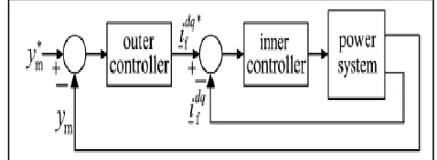
The E-STATCOM controller consists of an inner control loop and outer control loop shown in Fig.2.The outer control loop may be an ac voltage or dc-link voltage or FLC controller, sets the reference current for the inner current controller. The generic measured signal ym depends on the type of outer loop control. Where a phase-locked loop (PLL) [15] is used to track the grid-voltage angle θg from the grid-voltage vector from which the control algorithm is implemented in dq-reference frame. The superscript “*” in fig.2 denotes the corresponding reference signal.
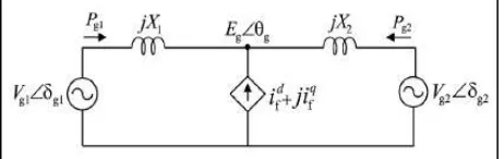
Fig. 3: Equivalent circuit of two-machine system with E-STATCOM.
Here the outer control loop is assumed to be a FLC controller. For this reason, we assume that the infusion active and reactive powers in the steady state are zero. The speed of inner control loop is much more than outer control loop for designing the series controller to security stability. E-STATCOM can be taken as ideal current source as shown in fig.3. for analysis. The level of Fuzzy Logic Controller gave by the converter depends on upon how much the active power yield from the generators is adjusted by the infused current. For the system in Fig.3, the adjustment in active power yield from the generators because of infused dynamic and responsive force from the E-STATCOM is calculated as in
∆𝑃𝑔1,𝑝 ≈-𝛤p𝑝𝑖𝑛𝑗, ∆𝑃𝑔2,𝑝 ≈-(1 − 𝛤p)𝑝𝑖𝑛𝑗,
∆𝑃𝑔1,𝑄 ≈ [
𝑉𝑔1𝑉𝑔2sin(𝛿𝑔10−𝛿𝑔20)𝑎(1−𝑎)
𝐸𝑔02 ]𝑄𝑖𝑛𝑗 (2)
∆𝑃𝑔2,𝑄 ≈− [
𝑉𝑔1𝑉𝑔2sin(𝛿𝑔10−𝛿𝑔20)𝑎(1−𝑎)
𝐸𝑔02 ]𝑄𝑖𝑛𝑗
From the corresponding generators (∆pg1,p, ∆pg2,p,) and (∆pg1,Q, ∆pg2,Q,) represent the change in active power due to injected active power (pinj) and reactive power(Qinj), respectively .ɾp, pinj and Qinjare given by
Γp=([(1−𝑎)𝑉𝑔1]2+𝑎(1−𝑎)𝑉𝑔1𝑉𝑔2cos(𝛿𝑔10−𝛿𝑔20))
𝐸𝑔02
𝑃𝑖𝑛𝑗 ≈ 𝐸𝑔0𝑖
𝑓𝑑 , 𝑄𝑖𝑛𝑗 ≈ −𝐸𝑔0𝑖𝑓
𝑞 (3)
The initial steady-state PCC voltage magnitude and generator rotor angles(δg10, δg20) correspond to the operating point where the converter is in ideal mode. The change in active power output from the generators depends on the location of the converter a as well as on the amount of injected active and reactive power from equation (2) and (3). From equation (2) the effect of reactive power injection depends on the magnitude and direction of transmitted power from the generators.
III. FLC CONTROLLER DESIGN
The derivation of the FLC controller from locally measured signals will be prepared in this section.
Derivation of Control Input Signals
locally measured signals θg and 𝑃𝑡𝑟𝑎𝑛 at different E-STATCOM connection points using the dynamic generator rotor angles δg1, δg2 and is given by
𝜃𝑔=𝛿𝑔2+tan−1[
(1−𝑎)𝑉𝑔1sin(𝛿𝑔1−𝛿𝑔2)
(1−𝑎)𝑉𝑔1cos(𝛿𝑔1−𝛿𝑔2)+𝑎𝑉𝑔2] (4)
𝑃𝑡𝑟𝑎𝑛=
𝑉𝑔1𝑉𝑔2sin(𝛿𝑔1−𝛿𝑔2)
𝑋1+𝑋2 (5)
The PCC-voltage magnitude along the line Eg does not change significantly from a small-signal point of view. The required control input signals can be derived from the PCC-voltage phase and transmitted active power as [14]
𝑑𝜃𝑔
𝑑𝑡 ≈ Γp𝑤𝑔0∆𝑤𝑔1+(1-Γp)𝑤𝑔0∆𝑤𝑔2 (6) 𝑑𝑃𝑡𝑟𝑎𝑛
𝑑𝑡 ≈ {
𝑉𝑔1 𝑉𝑔2 cos (𝛿𝑔10−𝛿𝑔20)
𝑋1+𝑋2 }𝑤𝑔0[∆𝑤𝑔1−∆𝑤𝑔2] (7)
Where the constant ∟p has been defined in the previous section. The nominal system frequency is represented by ωg0 where as ωg0, ωg1 and represent the speed variation of the generators in p.u. The electromechanical dynamics for each generator is given by
2𝐻𝑔𝑖 𝑑∆𝑤𝑔𝑖
𝑑𝑡 =∆𝑇𝑚𝑖− ∆𝑇𝑔𝑖− 𝐾𝐷𝑚𝑖∆𝑤𝑔𝑖 (8)
Where Hgi ωgi, ∆Tmi,, ∆Tgi, kDmi and represent inertia constant, speed variation, change in input torque, change in output torque and mechanical damping constant for the the generator, respectively. This is explained in the FLC controller design. For ∆ωg12=∆ωg1-∆ωg2 the two machine system as shown in Fig.1, damping is related to the variation of the speed difference between the two generators. From equation (2) and (3), it can be observed that when the compensators installed at the generator terminals (i.e. a=0 and a=1) the change in the output power from the generators due to injected active power is maximum., The derivative of PCC-voltage phase is zero [see (6)] At this place. This means that scales the speed variation of the two generators depending on the location of E-STATCOM and its magnitude changes in proportion to the level of damping by active power injection. Therefore, is an appropriate input signal for controlling the active power injection. On the other hand, it can be understood from (2) that the change in the output power from the generators due to injected reactive power is maximum at the electrical midpoint of the line (i.e.,a-0.5 ) and minimum at the generator terminals(i.e. a=0 and a=1). As the changes in the power output of the two generators are the same in magnitude and opposite in sign, a signal that varies linearly with the speed variation between the two generators, is ∆ωg2 an appropriate signal to control reactive power injection. This information can be obtained from the derivative of the transmitted active power dptran\dt.
Estimation of Control Input Signals
The aim of the algorithm is therefore to estimate the signal components that consist of only the low-frequency electromechanical oscillation in the measured signals θg and Ptran. By using a PLL with bandwidth much higher than the frequency of electromechanical oscillations, the derivative of the PCC-voltage phase can be obtained from the change in frequency estimate of the PLL (∆ωg=dθ\d). Therefore, the low-frequency electromechanical oscillation component can be extracted directly from the frequency estimate of the PLL. From the estimated control input signals and, which contain only a particular oscillation frequency component, the reference injected active and reactive current components (id*
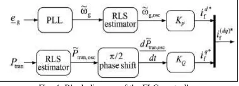
f, id*f) from the E-STATCOM can be calculated to setup the FLC controller as in Fig. 4. The terms KP and KD and represent proportional controller gains for the active and reactive current components, respectively. To describe the estimation algorithm, an input signal which could be either ωg or Ptran, as shown in Fig. 4, is considered. Following a power system disturbance, will consist of an average value that varies slowly and a number of low-frequency are excited by the disturbance.
Fig. 4: Block diagram of the FLC controller.
For simplicity, let us assume that there exists a single oscillatory component in the input signal. Therefore, the input signal consists of an average component Yavg and Yosc an oscillatory component which can be modeled as
y(t)=𝑌𝑎𝑣𝑔(𝑡) + 𝑌𝑝ℎ(𝑡) cos[𝜔𝑜𝑠𝑐t+ϕ(t)]
Where is YOSC expressed in terms of its amplitude (Yph), frequency ωosc and(ⱷ) phase . The model in (9) is rewritten using the oscillation angle as θosc(t)=ωosc(t)
y(t)=𝑌𝑎𝑣𝑔(𝑡) + 𝑌𝑝ℎ,𝑑(𝑡) cos(𝜃𝑜𝑠𝑐(t))- 𝑌𝑝ℎ,𝑞(𝑡)sin(𝜃𝑜𝑠𝑐(𝑡))
𝑌𝑝ℎ,𝑑(𝑡) = 𝑌𝑝ℎ(𝑡) cos(∅(𝑡)), 𝑌𝑝ℎ,𝑞(𝑡) = 𝑌𝑝ℎ(𝑡) sin(∅(𝑡)), (9)
(IJSTE/ Volume 3 / Issue 02 / 036)
˜h(k)=h˜(k−1)+G(k)[ .
y(k)−Φ(k)h˜(k−1)]
.
With
h(k)=[𝑌𝑎𝑣𝑔(𝑘) 𝑌𝑝ℎ,𝑑(𝑘) 𝑌𝑝ℎ,𝑞(𝑘) ]𝑇
ф(k)=[1 cos(𝜃𝑜𝑠𝑐(𝑘)) -sin(𝜃𝑜𝑠𝑐(𝑘))]. (10)
Calling the I as identity matrix, the gain matrix G and covariance matrix R are calculated recursively starting with an initial invertible matrix as R(0) as
G(k)= 𝑅(𝑘−1)Ф 𝑇(𝑘)
𝜆+Ф(𝑘)𝑅(𝑘−1)Ф𝑇(𝑘) (11) R(k)=[I−G(k)Φ(k)]R(k−1)/λ (12)
Where 𝛾 represents the forgetting factor for the RLS algorithm such that 0 < 𝛾 < 1 With Ts representing the sampling time, the steady-state bandwidth of the RLSα RLS and the estimation error 𝜖(k) are given by
𝛼𝑅𝐿𝑆 = (1−𝜆)
𝑇𝑠 ,e(k)=y(k)-ф(K)h(K-1). (13)
Modification in the Conventional RLS Algorithm the selection of αRLS is a tradeoff between a good selectivity for the estimator and its speed of response [13], [14]. A high forgetting factor results in low estimation speed with good frequency selectivity. With increasing estimation speed (decreasing), the modes.
Fig. 5: Block diagram of the modified RLS estimator for multiple oscillation.
Frequency selectivity of the algorithm reduces. For this reason, the conventional RLS algorithm must be modified in order to achieve fast transient estimation without compromising its steady-state selectivity. In this paper, this is achieved with the use of variable forgetting factor as described in [13]. When the RLS algorithm is in steady-state, its bandwidth is determinedly the steady-state forgetting factor . If a rapid change is detected in the input (i.e., if the estimation error magnitude, exceeds a predefined threshold), will be modified to a smaller transient forgetting factor δtr . Thus, by using a high-pass filter with time constant, δ will be slowly increased back to its steady-state value δSS .Besides δ, the performance of the estimation method depends on accurate knowledge of the oscillating frequency ωOSC,. This frequency is dependent on the system parameters and its operating conditions. If the frequency content of the input changes, the estimator will give rise to a phase and amplitude error in the estimated quantities. Therefore, a frequency adaptation mechanism as described in [14] is implemented to track the true oscillation frequency of the input from the estimate of the oscillatory component, YOSC.
Modification for Multiple Oscillation Modes
The investigated control method has been derived under the assumption of a single oscillatory frequency component in the input signal. A brief description of how the proposed algorithm can be extended for multi-area system with multiple oscillation modes will be briefly presented here for future reference. Assuming that the input signal contains oscillatory components, (9) must be modified as
y(t)=𝑌𝑎𝑣𝑔(𝑡) + ∑𝑁𝑖=1𝑌𝑜𝑠𝑐,𝑖
=𝑌𝑎𝑣𝑔(𝑡) + ∑𝑁𝑖=1𝑌𝑝ℎ,𝑖(𝑡)cos [𝜔𝑜𝑠𝑐,𝑖𝑡 + 𝜙𝑖(𝑡)] (14)
Where the ith oscillation mode YOSC,i with(i=1,2,3…..N) is expressed in terms of its amplitude (YPH, i)frequency(ωosc,i) ,and phase(ⱷi). Using the model in (13), the RLS described in the previous sections (including variable forgetting factor and frequency adaptation for each considered oscillation mode) can be modified as described in Fig.5. Thus, the FLC controller in Fig. 4 can be modified accordingly to control each mode independently. Observe that the phase-shift applied for calculation of the reference currents depends on the investigated system and needs to be calculated for each oscillatory mode [9].
IV. STABILITY ANALYSIS OF SYSTEM MODEL
𝑖𝑓𝑑≈ 𝐾𝑝𝜔𝑔𝑜[𝛤𝑝∆𝜔𝑔1+ (1 − 𝛤𝑝)∆𝜔𝑔2
𝑖𝑓𝑞≈ 𝐾𝑄𝜔𝑔𝑜{
𝑉𝑔1𝑉𝑔2cos(𝛿𝑔10−𝛿𝑔20)
𝑋1+𝑋2 }[∆𝜔𝑔1− ∆𝜔𝑔2] (15)
Where the constant is as defined in (3). Linearizing around an initial steady-state operating point, the small-signal dynamic model of the two-machine system with the E-STATCOM in per unit is developed as in
𝑑 𝑑𝑡[
∆𝜔𝑔1
∆𝛿𝑔12
∆𝜔𝑔2
] = [
𝛽11 𝛽12 𝛽13
𝜔𝑔0 0 −𝜔𝑔0
𝛽31 𝛽32 𝛽33
] [ ∆𝜔𝑔1
∆δg12
∆𝜔𝑔2
] +[
1 2𝐻𝑔1 0
0 0
0 1
2𝐻𝑔2
] [ ∆𝑇∆𝑇𝑚1
𝑚2] (16)
Where ∆g12=∆g1-∆g2 represents the rotor angle difference between the two generators and other signals as defined previously. Assuming no mechanical damping and the initial steady-state speed of the generators ωg0 set to , the constants are derived as in
[
𝛽11 𝛽31
𝛽12 𝛽32
𝛽13 𝛽33
] =
[
𝜔𝑔0(𝐸𝑔0𝐾𝑝𝛤𝑝2+𝛤𝑄𝐾𝑄)
2𝐻𝑔1
𝜔𝑔0(𝛤𝑝𝐸𝑔0𝐾𝑝(1−𝛤𝑝)−𝛤𝑄𝐾𝑄)
2𝐻𝑔2
−𝑉𝑔1𝑉𝑔2cos(𝛿𝑔10−𝛿𝑔20)
2𝐻𝑔1(𝑋1+𝑋2)
𝑉𝑔1𝑉𝑔2cos(𝛿𝑔10−𝛿𝑔20) 2𝐻𝑔2(𝑋1+𝑋2)
𝜔𝑔0(𝛤𝑝𝐸𝑔0𝐾𝑝(1−𝛤𝑝)−𝛤𝑄𝐾𝑄)
2𝐻𝑔1
𝜔𝑔0(𝐾𝑝𝐸𝑔0(1−𝛤𝑝)2+𝛤𝑄𝐾𝑄)
2𝐻𝑔2 ]
Where is Γq given by
ΓQ =
[𝑽𝒈𝟏𝑽𝒈𝟐]𝟐sin(2(𝛿𝑔10−𝛿𝑔20))𝑎(1−𝑎)
2Eg0(X1+X2)
The terms 𝛽12 and 𝛽32 represent the synchronizing torque coefficients resulting from the selected operating point and the
contribution of the E-STATCOM is zero. The terms 𝛽12 and 𝛽33determine the damping torque coefficient provided by
theE-STATCOM with respect to the change in speed of the respective generator. To provide positive damping, 𝛽12 and 𝛽33should be
kp negative. For this, the sign of should be negative and the
Fig. 6: Real and reactive power part of the complex conjugate poles versus position Active power injection. (b) Reactive power injection. (c) Active and reactive power injection.
sign 𝐾𝑄 of should be chosen based on the sign of Γq. Generator 1 to Generator 2 the transmitted power will be positive and the
sign should be negative. The sign of should be opposite for the transmitted power in other direction. The terms and are the cross coupling terms between the two generator speed variations. With active power injection only, the cross coupling terms reduce the damping as the speed variation of the generators will be opposite at the oscillatory frequency. At the mass-scaled electrical midpoint of the line where, the damping that can be provided by is zero. Therefore, the active power injected by the E-STATCOM at this location is set to zero by the control algorithm. When moving away from this point towards the generator terminals, increases and at the same time the cross coupling terms decrease.
(IJSTE/ Volume 3 / Issue 02 / 036)
Fig. 8: Measured transmitted active power output following a three-phase fault with E-STATCOM connected at bus 7 ,bus 8,bus 9.
V. SIMULATION RESULTS
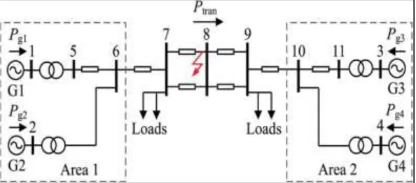
In section III the FLC is described and verified via MATLAB simulation using two area four machine power system as shown in fig.7. The rating of the system is 20/230 KV, 900 MVA, the generator parameters and the loading of transmission system are given in detail [9]. Initially the system is operating under steady state with active power of 400 MW from area 1 to area 2. Between one of the transmission lines bus 7 and 8 a three phase fault is applied to the system. After 120ms the fault is cleared by disconnecting the faulted line. A poorly damped oscillation is occurred after the fault clearing Due to the applied disturbance. The structure of FLC controller described in fig.4. At three different locations the performance of E-STACOM following the fault as shown in fig.8.When moving closer to the generator units a better damping is occurred in the small signal analysis for two machine system.
Fig. 9: Proposed FLC based Two Area Power System Fig. 10: Generator power of the two area Power System
VI. CONCLUSION
The E-STATCOM with FLC controller is developed in this paper. During power system disturbances for estimation of the low-frequency electromechanical oscillation components from locally measured signals a modified FLC controller has been used. This leads to fast, selective and adaptive estimation of signal components at the power oscillation frequency. To provide effective damping at different connection points of the E-STATCOM the FLC controller is used for the dynamic performance has been verified through simulation results. The power oscillations are less in power system with FLC controller when compared with POD controller. For the FLC controller the system can get stabilized. Besides, utilizing the frequency variation at the E-STATCOM association point as the information signal for the active power modulation, it has been demonstrated that dynamic force infusion is minimized at focuses in the force power system where its effect on FLC is negligible. This results in an ideal utilization of the available energy source.
REFERENCES
[1] N.G.Hingorani and L.Gyugyi, "Understanding FACTS, concepts and Technology of Flexible AC Transmission systems". New York, NY,USA:IEEE 2000.
[2] G.Cao, Z.Y.Dong, Y.Wang, P.Zang, and Y.T.Oh , "VSC based STATCOM controller for damping multimode oscillations" in Proc. IEEE power and Energy Soc.General meeting-convertion and Delivery of Electrical Energy in the 21st Century,Jul.2008,pp.1-8.
[3] M.Zarghami and M.L.Crow,"Damping inter area oscillations in power systems by STATCOMs" in Proc. 40th north Amer. Power symp.,Sep.2008 pp.1-6. [4] Z.Yang, C.Shen, L.Zang, M.L.Crow and S.Atcitty,"Integration of a STATCOM and battery energy storage,"IEEE Transactions power systems
vol.16,no.2,pp.254-260,May 2001.
[5] A.Arulampalam, J.B.Ekanayake,and N.Jenkins, "Application study of a STATCOM with energy storage", Proc. Inst. Electrical Engineering Generation, Transmission and Distribution vol.150, pp.373-384, July 2003.
[6] N.Wade, P.Taylor, Plang, and J.Svensson, "Energy storage for power flow management and voltage control on an 11KV UK Distribution Network," Prague,Czech Republic,CIRED paper 0824,Jun.2009.
[7] K.Kobayashi, M.Goto, K.Wu, Y.Yokomizu, and T.Matsumura, "Power system stability improvement by energy storage type STATCOM," in Proc. IEEE power Tech Conf., Bologna, Italy, jun. 2003,vol.2,DOI 10.1109/PTC.2003.1304302.
[8] L.Zang, and Y.Liu ,"Bulk power system low frequency oscillation supression by FACTS/ESS ," in Proc.IEEE PES power system Conf.Exp.oct.2004,pp.219-226.
[9] P.Kundur," Power system stability and control" .New York, NY, USA: Mc-Graw Hill,194.
[10] M.Noroozian,M.Ghandhari, G.Andersson, "A robust control strategy for shunt and series reactive compensators to damp electromechanical oscillations ,"IEEE Transactions on power Delivery,vol.16,pp.812-817,2001.
[11] Y.L.Tan, and Y.Wang ,"Design of shunt and series FACTS controller using adaptive nonlinear coordinated Design techniques," IEEE Transactions on power systems,vol.12, no.3,pp.1374-1379,1997.
[12] V.G.D.C. Samarasinghe and N.C. Pahalawaththa, "Stabilization of a multi-machine power system using nonlinear robust variable structure control, "Electric power systems Research,vol.43, pp.11-17, 1997.
[13] R.Majumder, B.C.Pal, C.Dufour, and P.Korba, "Design and real time implementation of robust FACTS controller for damping inter-area oscillations," IEEE Transactions on power systems," vol.21, no.2,pp.809-816,2006.
[14] A.Kazemi, M.V. Sohrforouzani, "Power system damping using fuzzy controlled FACTS devices," International journal of Electrical power and Energy systems, vol.28, pp.349-357,2006.
![Fig. 4 can be modified accordingly to control each mode independently. Observe that the phase-shift applied for calculation of the reference currents depends on the investigated system and needs to be calculated for each oscillatory mode [9]](https://thumb-us.123doks.com/thumbv2/123dok_us/7813626.1663393/4.612.224.392.256.393/accordingly-independently-observe-calculation-reference-investigated-calculated-oscillatory.webp)
![fig.7. The rating of the system is 20/230 KV, 900 MVA, the generator parameters and the loading of transmission system are given in detail [9]](https://thumb-us.123doks.com/thumbv2/123dok_us/7813626.1663393/6.612.198.415.49.266/rating-system-generator-parameters-loading-transmission-system-detail.webp)
